
VALUE AT THE SPINDLE
KYOCERA SGS Precision Tools (KSPT) is an ISO 9001:2015 Certified manufacturer of industry leading round solid carbide cutting tools. State of the art manufacturing and warehouse facilities have the capacity and processes to meet the quality and delivery demands of customers in all markets around the world. Complete inspections performed within its metallurgical lab and manufacturing quality departments ensure the use of high quality carbide and reliable manufacturing consistency regardless of when a cutting tool is produced.
KSPT is proud to have pioneered some of the world’s most advanced cutting technologies due to rigorous testing of tools, coatings, and materials within its Technical Center. It is this commitment to innovation that has launched patented products and technologies like the Z-Carb with its variable geometry and cutting edge preparation, Series 43 APR and APF ultra high performance aluminum cutting tools, and the JetStream coolant technology.
SGS has become an important part of the KYOCERA Precision Tools family, and while the name has changed, one thing has not. Its dedicated people and their relentless commitment to the customer. KSPT Technical Sales Engineers, Application Specialists, and Distribution Partners blanket the globe, delivering reliable service and support to all market segments. It is these people and products that drive innovative application strategies and cutting tool technologies into the end user, continually exceeding expectations and providing the most Value at the Spindle.

Solid Carbide Tools


Technical Centers in North America and Europe
Cutting Tool Innovation
Our mission is to deliver value at the spindle. We achieve this by engineering advanced, application-driven cutting tool geometries using the latest technologies and techniques. Every tool we design is built to push the limits of performance and move the industry forward.
• Precision measuring and tool monitoring technology
• Ongoing market research and innovation
• Unique, high-performance tool designs
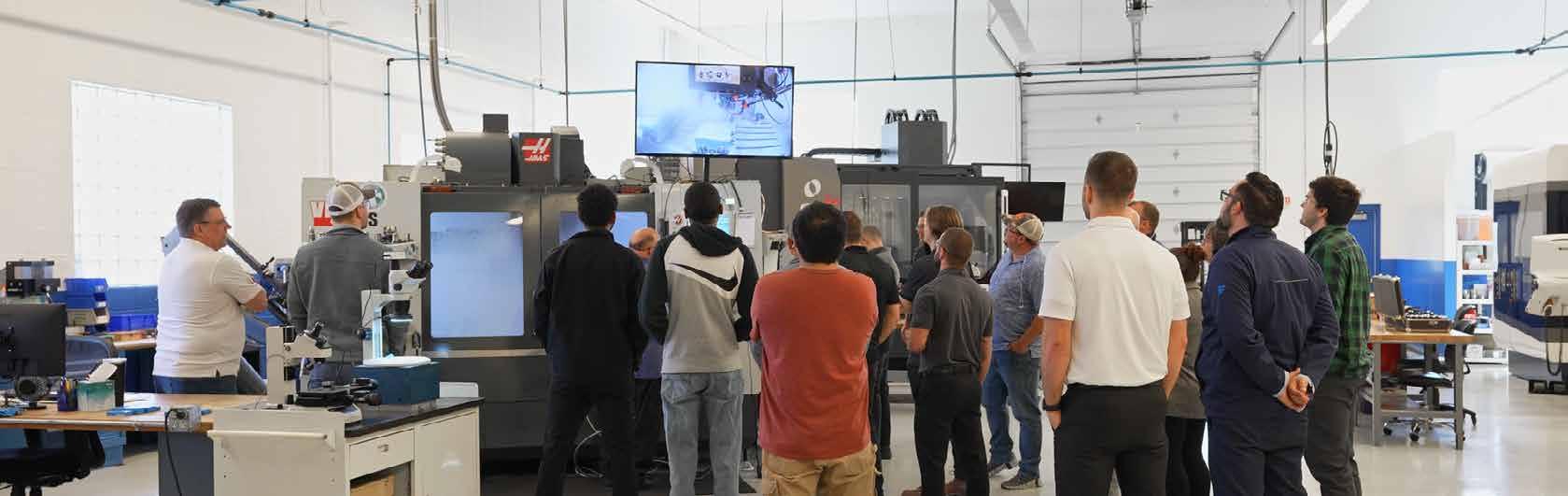
Technical Training & Education
We believe in empowering machinists at every stage of their journey. Our training programs are hands-on, immersive, and tailored to real-world challenges, because great tools are only as good as the people who run them.
• Core training for both customers and KYOCERA SGS team members
• On-site tool clinics and cutting demonstrations
• Online and on-site training options

Application Support & Testing
Every job is different and so is every solution. Our engineers work directly with you to replicate real machining conditions, test potential setups, and recommend the best approach, all without interrupting your own production.
• Extensive inventory of holders, fixturing, materials, coolants, and machines
• Application troubleshooting by phone, email, or video call
• In-house research and development for building real-world solutions

Comprehensive Tooling Services
Tooling Services Facilities
KYOCERA SGS delivers expert tooling services designed to extend tool life, improve performance, and meet your specific application needs. From Reconditioning, Recoating, and Regrinding to Custom Specials and Alterations, our solutions are backed by the deep expertise of our KYOCERA SGS Technical Support Teams.
We proudly provide tooling services across North America and Europe, offering precision support wherever you need it.
U .S .A . Europe
KYOCERA SGS Precision Tools
150 Marc Drive
Cuyahoga Falls, Ohio 44223 U.S.A. (330) 686-5700 sales@kyocera-sgstool.com
KYOCERA SGS Precision Tools
West Coast Service Center 1832 W. Collins Ave. Orange, California 92867 U.S.A. (714) 363-3701 sgswest@kyocera-sgstool.com
KYOCERA SGS Precision Tools 10 Ashville Way Wokingham, Berkshire RG41 2PL England (44) 1189-795-200 saleseu@kyocera-sgstool.com


Custom Engineered Tooling Solutions
Complex Solutions Made Easy
At the heart of our engineered custom tooling capabilities lies our dedication to providing our customers with comprehensive solutions that align seamlessly with their needs. With the ability to integrate patented, industry-leading designs into each uniquely tailored tool, we ensure a perfect fit for your specific application.
Technology-Driven Capabilities
• Complex custom tool designs
• Tailor-made machining solutions


• Complete project management • Custom End Mills
• Custom Drills
• Custom Reamers


• Custom Chamfer & Rounding
• Custom Threading
• Combination Tooling
• Bulb Tooling
• Dovetail & T-Slots
• Form Tooling
• Taper Ball Nose Tools
• Micro Tooling
KYOCERA SGS Precision Tools | Europe

KYOCERA SGS Precision Tools Europe
The state-of-the-art KYOCERA SGS Precision Tools Europe facility is located in Wokingham, England and is focused on the manufacture of special cutting tools, high accuracy form tools, tool modifications and regrinds. A highly skilled team of professionals specialise in the supply and support of high performance tools for the Aerospace, Medical, Power Generation, and Motorsport markets.
KYOCERA SGS Precision Tools Europe offers a full range of end mill and drill products:
• Multi-Million Euro Warehouse Stocking Full Range of Catalogue Products
• Same Day Shipment on Stock Items
• Multi-Lingual Sales and Technical Support
• Online Portal for Stock Availability
• High Performance Product and Application Training, Including KYOCERA SGS Tool Clinics

Additional Services
• A Fast Track for Special Tools Via Our Rapid Response Centre
• Inhouse PVD coating facility and R&D Centre
• Product Research and Development
• Product Engineering and Tool Application Support
• CAD/CAM Software Support

APPLICA TION EXPER T
Say hello to APEX: Application Expert KYOCERA SGS's enhanced web application designed to make your SGS tool selection and parameter setup faster and more effective!
OPTIMIZE TOOL PERFORMANCE


Gain essential application data to optimize tool performance, including cutting parameters and material recommendations.
SAVE TIME COMPARE AND CUSTOMIZE
Easily select application types, units, and materials with our user-friendly interface and autofill features.
Use powerful tools to tailor results, compare up to five options, and visualize ramping parameters with detailed drawings.
EXPORT AND SHARE
Generate PDFs with application data, add comments, and print precise line drawings with detailed specifications.

or Click the APEX Logo on any Product Detail Page.

Common Legend Leyenda habitual Légende commune Gemeinsame Legende


TO ORDER: Please specify quantity and EDP number.
PARA SU PEDIDO: Por favor especifique cantidad y número de EDP.
POUR COMMANDER: Veuillez préciser la quantité et le code article EDP.
BESTELLEN: Bitte Menge und EDV-Nummer angeben.
RETURN POLICY: An RMA number must accompany all product returns. Contact your Customer Service Representative for an RMA number.
DEVOLUCIONES: Todo material devuelto debe ir acompañado de un número de RMA correspondiente. Para solicitarlo, póngase en contacto con su Representante de Atención al Cliente.
POLITIQUE DE RETOUR: Tous les produits retournés doivent être accompagnés d’un numéro RMA. Contacter votre interlocuteur commercial pour obtenir un numéro RMA.
RÜCKNAHMEGARANTIE: Eine RMA-Nummer (Rücksendegenehmigung) muss bei allen Produktrücksendungen beiliegen. Wenden Sie sich bitte an Ihren Kundendienstmitarbeiter für RMA-Nummer.
REGULATION SAFETY GLASSES SHOULD ALWAYS BE WORN WHEN USING HIGH-SPEED CUTTING EQUIPMENT
DEBEN USARSE GAFAS PROTECTORAS CUANDO SE UTILICEN EQUIPOS DE ALTA VELOCIDAD
DES LUNNETTES DE SÉCURITE DOIVENT ÊTRE IMPÉRATIVEMENT PORTÉES LORS D’UTILISATION D’OUTILS À GRANDE VITESSE
BEI SCHNELLLAUFENDEN SPANABHEBENDEN MASCHINEN MÜSSEN IMMER DIE VORGESCHRIEBENEN SICHERHEITSBRILLEN GETRAGEN WERDEN
WARNING: This product can expose you to chemicals including Cobalt, which is known to the State of California to cause cancer. For more information go to www.p65warnings.ca.gov
ADVERTENCIA: Este producto puede exponerlo a químicos como el Cobalto, reconocido como cancerígeno en el estado de California. Para mas informacion visite esta pagina web: www.p65warnings.ca.gov
ATTENTION: Ce produit vous expose aux produits chimiques incluant le Cobalt, qui est reconnu par l'Etat de Californie a etre une cause de cancer. Pour plus d'information veuillez regarder sur: www.p65warnings.ca.gov
WARNUNG: Dieses Produkt kann Sie mit Chemikalien wie Kobalt aussetzen, das dem Staat Kalifornien als krebserregend bekannt ist. Für weitere Informationen, besuchen Sie: www.p65warnings.ca.gov
INTELLECTUAL PROPERTY PROPIEDAD INTELECTUAL PROPRIÈTÈ INTELLECTUELLE GEISTIGES EIGENTUM
KYOCERA SGS Precision Tools holds more than 20 patents globally. Please visit our website at www.kyocera-sgstool.com to learn more.
KYOCERA SGS Precision Tools posee más de 20 patentes a nivel mundial. Para más información, visite nuestra página web www.kyocera-sgstool.com.
KYOCERA SGS Precision Tools possède plus de 20 brevets mondialement reconnus. Pour plus d'information, veuillez consulter notre site web www.kyocera-sgstool.com.
KYOCERA SGS Precision Tools besitzt mehr als 20 Patente weltweit. Bitte besuchen Sie unsere Webseite www.kyocera-sgstool.com für weitere Informationen.
Common Legend Leyenda habitual Légende commune
Gemeinsame Legende
MATERIALS
MATERIALES MATÉRIAUX WERKSTOFFE
Steels (P) Aceros Aciers Stähle
Non-Ferrous (N) No Férricos Non Ferreux
Nichteisenmetalle
TOOL LENGTH
Stainless Steels (M)
Aceros Inoxidables
Aciers inoxydables
Nichtrostende Stähle
High Temp Alloys (S)
Aleaciones Termorresistentes
Alliages hautes températures
Warmfeste Legierungen
Cast Iron (K)
Acero de Fundición Fonte
Grauguss
Hardened Steels (H)
Aceros Endurecidos
Aciers Trempés
Gehärteter Stahl
End Mill Legend Leyenda fresas Légende fraise Fräser-Legende
END CONFIGURATIONS
CONFIGURACIONES DE LA PUNTA FORME DE L'OUTIL EN BOUT ENDENAUSFÜHRUNG
Ball Esférica
Boule
Kugelkopf
SHANK TYPE TIPO DE VÁSTAGO
TYPE DE QUEUE
SCHAFTART
Corner Plana con borde romo Rayon mit Eckenradius
Common Normal Dégagée
Standard Straight Recto Cylindrique Gerade
Square Plana Non rayonné Scharfkantig
SIDE PROFILE PERFIL LATERAL
PROFIL LATÉRAL
SEITENPROFI
Linear taper Perfil Cónico
Conique Droit Linear Kegel
WELDON DIN6535 HB
Drive Flat Plano en el zanco Entrainement méplat Spannfläche
COOLANT OPTIONS OPCIONES DE REFRIGERACIÓN OPTIONS DE REFROIDISSEMENT KÜHLSCHMIERMITTEL-OPTIONEN
Internal Coolant Refrigeración interna Refroidissement interne Innenkühlung
JetStream Coolant Slots Ranuras de refrigeración JetStream Fentes de refroidissement JetStream JetStreamKühlmittelschlitze
All tools are in Right Cut Direction unless noted
RAKE ANGLE
Drive Flat DIN 6535 HB Plano en el zanco DIN 6535 HB Entrainement méplat DIN 6535 HB Spannfläche DIN 6535 HB
Tapered Circle Segment Perfil Cónico de Segmento Circular Conique Segment de Cercle Tonnen Segment
Picatinny Recoil Groove
Fresa Riel Picatinny Rainure Décalée Picatinny
Picatinny Rückstoss Nut
HELIX ANGLES ANGULOS DE LAS HELICES SPANWINKEL ANGLES DE L'HÉLICE
Right Spiral Hélice con corte a la derecha Hélice droite Rechtsspirale
Left Spiral Hélice con corte a la izquierda Hélice gauche Linksspirale
Picatinny Dovetail Form
Fresa de Forma
Picatinny Cola de Milano
Queue d’aronde Picatinny
Picatinny Schwalbenschwanz Form
Variable Right Spiral Hélice con corte a la derecha y ángulo variable Hélice droite variable Rechtsspirale, variabel
ANGULO DE DESPRENDIMIENTO ANGLE DE COUPE SPANWINKEL
ADDITIONAL GEOMETRY GEOMETRÍAS ADICIONALES GÉOMÉTRIE SUPPLÉMENTAIRE WEITERE BAUFORMEN
Spacing
Positif
Positiv
Todas las herramientas son con corte a la derecha a menos que se indique lo contrario
Tous les outils ont une coupe à droite, sauf indications contraires
Alle Werkzeuge sind rechtsschneidend, soweit nicht anders angegeben
All tools are straight or non-tapered unless noted
Todas las herramientas son rectas o no cónicas a menos que se indique lo contrario
Tous les outils sont droits ou non coniques, sauf indication contraire
Alle Werkzeuge sind gerade oder nicht konisch, sofern nicht anders angegeben
Unequal Espaciado desigual de los filos
Denture décalée Nutenabstand Ungleich Chip Breaker Rompevirutas Brise-copeaux Spanteiler
Drill Legend Leyenda brocas Légende perçage
Bohrer-Legende
SHANK TYPE
TIPO DE VÁSTAGO
TYPE DE TIGE SCHAFTART
Common Normal
Dégagée Standard Straight Recto Cylindrique Gerade 3xD
HELIX ANGLES
ANGULOS DE LAS HELICES ANGLES DE L'HÉLICE SPANWINKEL
Right Spiral Hélice con corte a la derecha
Hélice à droite Rechtsspirale
POINT ANGLE
ANGULO DE PUNTA
POINT D’ANGLE SPITZENWINKEL
None Ninguno Aucun gerade genutet
COOLANT OPTIONS
OPCIONES DE REFRIGERACIÓN OPTIONS DE REFROIDISSEMENT KÜHLSCHMIERMITTEL-OPTIONEN
Internal Coolant Refrigeración interna Refroidissement interne Innenkühlung
External Coolant Refrigeración externa Refroidissement externe Auskühlung
CHAMFER ANGLE ÁNGULO DE CHAFLÁN ANGLE DE CHANFREIN FASENWINKEL
Point Angle
Angulo de la Punta Angle de pointe Spitzenwinkel
NUMBER OF MARGINS
NÚMERO DE MÁRGENES
Point Angles Ángulos de punta Angles de pointe Spitzenwinkel
Chamfer Angle Ángulo de chaflán Angle de chanfrein Fasenwinkel
NOMBRE DE MARGES ANZAHL DER RÄNDER NUMBER OF FLUTES
Leyenda ranuradores Légende détourage
Konturenfräser-Legende
SHANK TYPE TIPO DE VÁSTAGO TYPE DE TIGE SCHAFTART
RAKE ANGLE ANGULO DE DESPRENDIMIENTO ANGLE DE PENTE SPANWINKEL
Recto Cylindrique Gerade
HELIX ANGLES ANGULOS DE LAS HELICES ANGLES DE L'HÉLICE SPANWINKEL
Right Spiral Hélice con corte a la derecha Hélice à droite Rechtsspirale
Left Spiral Hélice con corte a la izquierda Hélice à gauche Linksspirale
ADDITIONAL GEOMETRY GEOMETRÍAS ADICIONALES GÉOMÉTRIE SUPPLÉMENTAIRE WEITERE BAUFORMEN
Left Hand Cut Direction Fresado sentido izquierda Coupe vers la gauche Rechtsschneidend
Right Hand Cut Direction Fresado sentido derecha Coupe vers la droite Linksschneidend
Chip Breaker Rompevirutas Brise-copeaux Spanbrecher
Coatings
Ti-NAMITE and Di-NAMITE Tool Coatings are specifically engineered for KSPT solid carbide rotary tools. The coating lineup includes proprietary processes that result in optimized tool life and increased speed and feed rates in a variety of applications.
Ti-NAMITE
Nitride (TiN)
Ti-NAMITE-A

Ti-NAMITE-B
(TiCN)
Ti-NAMITE-X Proprietary (TX) black Nano Composite 1–5 microns
Di-NAMITE Crystalline Diamond (Diamond) black Monolayer 6–20 microns >8000 0.15–0.20 800°C / 1470°F
/

A general purpose coating with good adhesion and abrasion resistant properties. Suitable for a wide variety of materials.
Excellent thermal and chemical resistance allows for dry cutting and improvements in performance of carbide. The coating has a high hardness giving great protection against abrasive wear and erosion.
This ceramic based coating ensures a smooth surface and a low affinity to cold welding or edge build up, which makes it optimal for aluminum, copper, and other non-ferrous applications. It has high toughness and high hardness.
A very wear resistant coating with high toughness and shock resistance. Good in interrupted cuts found in applications like milling.
The structural design of Ti-Namite-X is adapted to meet a diverse range of applications; everything from high- and low-alloy steels to hardened materials (up to 65 HRC core hardness). Ti-Namite-X is suitable for operations which require high cutting speeds, high temperatures at the cutting edge, and high metal removal rates.
This is the hardest coating available with the best abrasion resistance. Diamond coating is suitable for machining highly abrasive, non-ferrous materials such as CFRP and graphite.
Features include high wear resistance, reduced friction, and excellent prevention of edge build up. This coating provides superior material removal rates and tool life when used in high performance operations with difficult to machine materials like titanium.
This coating demonstrates a superior combination of hardness and adhesion in hard machining of molds and dies and machining high-alloy stainless steels for high temperature applications such as turbines. The smooth surface ensures optimum surface quality and decreases the temperature in the cutting zone by reducing friction.
The nano-layers of this coating provide high hardness for exceptional wear resistance and high oxidation resistance that allows for operation at high temperatures. The layered structure also gives the coating the toughness required to resist chipping. Megacoat Nano is particularly effective in high efficiency machining applications.
Other coatings available upon request.
Ti-NAMITE Titanium Nitride (TiN)
Ti-NAMITE-A Aluminum Titanium Nitride (AlTiN)
Ti-NAMITE-B Titanium DiBoride (TiB2)
Ti-NAMITE-C Titanium Carbonitride (TiCN)
Ti-NAMITE-X Proprietary (TX)
Di-NAMITE Crystalline Diamond (Diamond)
Ti-NAMITE-M Proprietary (TM)
Ti-NAMITE-H Proprietary (TH)
MEGACOAT NANO Proprietary (MN)
Coating Application Guide
VALUE AT THE SPINDLE
Solid Car bide Tools
High Performance End Mills

FRESAS DE ALTO RENDIMIENTO
4 filos, penetración / inclinación / desbastador, punta cuadrada, fraccional
4 filos, penetración / inclinación / desbastador, radio angulado, fraccional
4 filos, penetración / inclinación / desbastador, punta cuadrada, métrico
4 filos, penetración / inclinación / desbastador, radio angulado, métrico
Z1PCR 4 filos, inclinación variable, radio angulado, fraccional
Z1P 4 filos, inclinación variable, punta cuadrada, fraccional
Z1PB 4 filos, inclinación variable, punta esférica, fraccional
4 filos, inclinación variable, largo alcance, radio angulado, fraccional
Z1PLB 4 filos, inclinación variable, punta esférica, largo alcance, fraccional
Z1MPCR 4 filos, inclinación variable, radio angulado, métrico
4
4 filos, inclinación variable, medio alcance,
Z-Carb-HTA ZH1CR 4 filos, geometría variable, aleaciones termorresistentes,
4 filos, geometría variable, aleaciones termorresistentes, radio angulado, métrico
ZH1MCRS 4 filos, geometría variable, aleaciones termorresistentes, versión corta, radio
Z-Carb-MD ZD1CR 4 filos, geometría variable, materiales duros, largo alcance, radio angulado,
4 filos, geometría variable, materiales duros, largo alcance, radio angulado, métrico
5 filos, desbastador, largo alcance, punta
5 filos, desbastador, radio angulado, métrico
55 5 filos, acabador y semiacabador, punta cuadrada, fraccional
55CR 5 filos, acabador y semiacabador, radio angulado, fraccional
55B 5 filos, acabador y semiacabador, punta esférica, fraccional
5 filos, acabador y semiacabador,
6 filos, mecanizado de alta velocidad, punta cuadrada, fraccional
2 filos, contorneado, largo alcance, punta esférica, métrico
Recomendaciones de velocidades y avances mostradas tras cada serie
Fraisage
End Mill Matrix
Preferred materials for each Series are designated below.
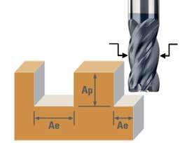
Cut depths (Ae & Ap) are based on a percentage of the cutter diamter (DC) Material
Picatinny Dovetail F PRT
Ski-Carb 44 181
S-Carb 2 Flute 47 174
S-Carb 3 Flute 43 152
S-Carb APR-3 43APR-3 141
S-Carb APR-4 43APR-4 144
S-Carb APF 43APF 146
S-Carb APF-B 43APF-B 150
Picatinny Groove NF PRT 130 & 133
Picatinny Dovetail NF PRT 130 & 133
Slow Helix 27 127
Coolant required in these materials Plunging not recommended in these materials
View the KYOCERA SGS APEX application for detailed technical information www.kyocera-sgstool.com/apex
Preferred Cut Type for Series ★ Best Better Good (blank) Not Recommended
Unless blank, a high quality wall or floor finish can be achieved with any Series with adjusted speed & feed.
End Mill Matrix
Preferred Entry Method for Series Preferred Tool Path for Series
Speed & Feed are based on ramp angle.


For rough milling, HEM tool paths are usually preferred in most situations, however, Standard paths may be more efficient using suitable tools with moderate to heavy cut types.

View the KYOCERA SGS APEX application for detailed technical information www.kyocera-sgstool.com/apex
End Mill Matrix
End Mill Matrix
Tool
Tool
Tool
Application Tips
Tool
Tool Holders
Tool Holders
Tool Holders
Tool Holders
Workpiece
Workpiece
Workpiece
• Whenever possible, select an end mill with the largest diameter, shortest flute length, and shortest overall length for the best rigidity
• Whenever possible, select an end mill with the largest diameter, shortest flute length, and shortest overall length for the best rigidity
• Whenever possible, select an end mill with the largest diameter, shortest flute length, and shortest overall length for the best rigidity
• Long flute tools are not intended for pocketing, slotting, or heavy profiling – limit Rw to .02D
• Long flute tools are not intended for pocketing, slotting, or heavy profiling – limit Rw to .02D
• Long flute tools are not intended for pocketing, slotting, or heavy profiling – limit Rw to .02D
• High Performance tools minimize cycle time and extend tool life
• High Performance tools minimize cycle time and extend tool life
• High Performance tools minimize cycle time and extend tool life
• Whenever possible, select an end mill with the largest diameter, shortest flute length, and shortest overall length for the best rigidity
• Holders with adequate gripping pressure and TIR are required
• Holders with adequate gripping pressure and TIR are required
• Holders with adequate gripping pressure and TIR are required
• Long flute tools are not intended for pocketing, slotting, or heavy profiling – limit Ae to .02D
• Stub holders or zero length collet style holders are recommended for heavy stock removal
• Stub holders or zero length collet style holders are recommended for heavy stock removal
• Stub holders or zero length collet style holders are recommended for heavy stock removal
• High Performance tools minimize cycle time and extend tool life
• When using solid holders, hand ground screw flats are not recommended
• When using solid holders, hand ground screw flats are not recommended
• When using solid holders, hand ground screw flats are not recommended
• Holders with adequate gripping pressure and TIR are required
• Secure clamping of the workpiece will reduce chatter and deflection
• Secure clamping of the workpiece will reduce chatter and deflection
• Stub holders or zero length collet style holders are recommended for heavy stock removal
• Secure clamping of the workpiece will reduce chatter and deflection
• When using solid holders, hand ground screw flats are not recommended
Machine
Machine
Machine
Workpiece
Machine
Coolant
Coolant
Coolant
Coolant
Methods
Methods
Methods
Methods
• Spindle must be in optimum condition for precise TIR and maximum tool life
• Spindle must be in optimum condition for precise TIR and maximum tool life
• Spindle must be in optimum condition for precise TIR and maximum tool life
• Sufficient horsepower is required to perform at recommended speeds and feeds
• Sufficient horsepower is required to perform at recommended speeds and feeds
• Sufficient horsepower is required to perform at recommended speeds and feeds
• Secure clamping of the workpiece will reduce chatter and deflection
• Reduce rates for low power machines to prevent workpiece and / or tool damage
• Reduce rates for low power machines to prevent workpiece and / or tool damage
• Reduce rates for low power machines to prevent workpiece and / or tool damage
• Spindle must be in optimum condition for precise TIR and maximum tool life
• Avoid re-milling chips through use of air blast or liquid coolant as necessary
• Avoid re-milling chips through use of air blast or liquid coolant as necessary
• Sufficient horsepower is required to perform at recommended speeds and feeds
• Avoid re-milling chips through use of air blast or liquid coolant as necessary
• Maintain clean coolant with appropriate concentration
• Maintain clean coolant with appropriate concentration
• Maintain clean coolant with appropriate concentration
• Reduce rates for low power machines to prevent workpiece and / or tool damage
• General recommendations:
• General recommendations:
• General recommendations:
• Avoid re-milling chips through use of air blast or liquid coolant as necessary
–Water Soluble Oil or Air Blast: Tool Steels, Mold & Die Steels, Carbon or Alloy Steels
–Water Soluble Oil or Air Blast: Tool Steels, Mold & Die Steels, Carbon or Alloy Steels
–Water Soluble Oil or Air Blast: Tool Steels, Mold & Die Steels, Carbon or Alloy Steels
• Maintain clean coolant with appropriate concentration
–Water Soluble Oil: Stainless Steels, Titanium, High Temperature Alloys, Non-Ferrous Alloys
–Water Soluble Oil: Stainless Steels, Titanium, High Temperature Alloys, Non-Ferrous Alloys
–Water Soluble Oil: Stainless Steels, Titanium, High Temperature Alloys, Non-Ferrous Alloys
• General recommendations:
—Water Soluble Oil or Air Blast: Tool Steels, Mold & Die Steels, Carbon or Alloy Steels
• Climb milling is generally preferred
• Climb milling is generally preferred
• Climb milling is generally preferred
—Water Soluble Oil: Stainless Steels, Titanium, High Temperature Alloys, Non-Ferrous Alloys
• Attention to programming details, tool holders, TIR, balance, fixturing, etc. improve cutting tool performance and extend tool life
• Attention to programming details, tool holders, TIR, balance, fixturing, etc. improve cutting tool performance and extend tool life
• Attention to programming details, tool holders, TIR, balance, fixturing, etc. improve cutting tool performance and extend tool life
• Climb milling is generally preferred
• Attention to programming details, tool holders, TIR, balance, fixturing, etc. improve cutting tool performance and extend tool life
END MILLING GUIDELINE
END MILLING GUIDELINE
END
MILLING GUIDELINE
END MILLING GUIDELINE
D1 = cutting diameter L2 = flute length
D1 = cutting diameter L2 = flute length
D1 = cutting diameter L2 = flute length
DC = cutting diameter APMX = flute length
Speeds and Feeds for Cut Types are based on Radial Width ( Rw ) and Axial Depth ( Ad )
Speeds and Feeds for Cut Types are based on Radial Width ( Rw ) and Axial Depth ( Ad )
Speeds and Feeds for Cut Types are based on Radial Width ( Rw ) and Axial Depth ( Ad )
Speeds and Feeds for Cut Types are based on Radial Width ( Ae ) and Axial Depth ( Ap )
Reductions to Speeds and Feeds may be necessary when:
Reductions to Speeds and Feeds may be necessary when:
Reductions to Speeds and Feeds may be necessary when:
• Rw and Ad exceed recommendations
• Rw and Ad exceed recommendations
• Rw and Ad exceed recommendations
Reductions to Speeds and Feeds may be necessary when: • Ae and Ap exceed recommendations
• Using long flute or extended reach tools
• Using long flute or extended reach tools
• Using long flute or extended reach tools
• Using long flute or extended reach tools
• Using long tool holders
• Using long tool holders
• Using long tool holders
• Using long tool holders
• Machining materials harder than listed
• Machining materials harder than listed
• Machining materials harder than listed
• Machining materials harder than listed
ENTRY METHODS
ENTRY METHODS
ENTRY METHODS
ENTRY METHODS
Pre-Drilled Hole
Pre-Drilled Hole
Pre-Drilled Hole
Pre-drilling is the preferred entry method for most applications.
Pre-drilling is the preferred entry method for most applications.
Pre-drilling is the preferred entry method for most applications.
Pre-drilling is the preferred entry method for most applications.
Alternative methods are helical and straight ramping. High ramp angles require reduced feed. Lower ramp angles will allow higher feed rates and extend tool life. Use slotting speeds and feeds for ramp angles of 1° to 2°. Reduce feed to 25% when ramp angles approach 6°. General purpose tools and/or difficult to machine materials will require lower ramp angles and reduced feed.
Alternative methods are helical and straight ramping. High ramp angles require reduced feed. Lower ramp angles will allow higher feed rates and extend tool life. Use slotting speeds and feeds for ramp angles of 1° to 2°. Reduce feed to 25% when ramp angles approach 6°. General purpose tools and/or difficult to machine materials will require lower ramp angles and reduced feed.
Alternative methods are helical and straight ramping. High ramp angles require reduced feed. Lower ramp angles will allow higher feed rates and extend tool life. Use slotting speeds and feeds for ramp angles of 1° to 2°. Reduce feed to 25% when ramp angles approach 6°. General purpose tools and/or difficult to machine materials will require lower ramp angles and reduced feed.
Alternative methods are helical and straight ramping. High ramp angles require reduced feed. Lower ramp angles will allow higher feed rates and extend tool life. Use slotting speeds and feeds for ramp angles of 1° to 2°. Reduce feed to 25% when ramp angles approach 6°. General purpose tools and/or difficult to machine materials will require lower ramp angles and reduced feed.
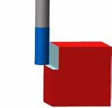
Plunge only in non-ferrous and short-chipping materials using slotting speeds and 25% slotting feeds.
Plunge only in non-ferrous and short-chipping materials using slotting speeds and 25% slotting feeds.
Plunge only in non-ferrous and short-chipping materials using slotting speeds and 25% slotting feeds.
Plunge only in non-ferrous and short-chipping materials using slotting speeds and 25% slotting feeds.
Plunge
Plunge
Plunge
Recomendaciones de uso
Herramientas
• Siempre que sea posible, seleccione la herramienta de mayor diámetro y menor longitud total y de filo para obtener una mayor rigidez.
SUGERENCIAS DE APLICACIÓN DE FRESADO ( Para sugerencias adicionales, consulte las series específicas de cada herramienta)
SUGERENCIAS DE APLICACIÓN DE FRESADO ( Para sugerencias adicionales, consulte las series específicas de cada herramienta)
SUGERENCIAS DE APLICACIÓN DE FRESADO ( Para sugerencias adicionales, consulte las series específicas de cada herramienta)
Herramientas
Herramientas
Herramientas
Portaherramientas
Portaherramientas
Portaherramientas
Portaherramientas
Pieza a maquinar
Máquina
Pieza a maquinar
Pieza a maquinar
Pieza a maquinar
Máquina
Máquina
Máquina
Refrigeración
Refrigerante
Refrigerante
Refrigerante
Métodos
Métodos
Métodos
Métodos
GUÍAS DE FRESADO
• Las herramientas con filos largos no son recomendadas para operaciones de apertura de cajas en el maquinado, operación de ranurado o perfilado pesado – limitar la profundidad radial (Ae) a .02D
• Las herramientas de alto desempeño minimizan el tiempo de ciclo del maquinado y extienden la vida útil de la herramienta
• Siempre que sea posible, seleccione el cortador con el mayor diámetro, largo de filo y largo total mas corto posible para obtener una mejor rigidez.
• Siempre que sea posible, seleccione el cortador con el mayor diámetro, largo de filo y largo total mas corto posible para obtener una mejor rigidez.
• Siempre que sea posible, seleccione el cortador con el mayor diámetro, largo de filo y largo total mas corto posible para obtener una mejor rigidez.
• Las herramientas con filos largos no son recomendadas para operaciones de apertura de cajas en el maquinado, operación de ranurado o perfilado pesado – limitar la profundidad radial (Rw) a .02D
• Las herramientas con filos largos no son recomendadas para operaciones de apertura de cajas en el maquinado, operación de ranurado o perfilado pesado – limitar la profundidad radial (Rw) a .02D
• Los Portaherramientas deberán tener buena presión de amarre para la sujeción de la herramienta y una concentricidad máxima indicada (TIR)
• Las herramientas con filos largos no son recomendadas para operaciones de apertura de cajas en el maquinado, operación de ranurado o perfilado pesado – limitar la profundidad radial (Rw) a .02D
• Las herramientas de alto desempeño minimizan el tiempo de ciclo del maquinado y extienden la vida útil de la herramienta
• Se recomienda usar portaherramientas de amarre directo cortos, o de boquilla con longitud cero para lograr un máximo arranque de viruta
• Las herramientas de alto desempeño minimizan el tiempo de ciclo del maquinado y extienden la vida útil de la herramienta
• Las herramientas de alto desempeño minimizan el tiempo de ciclo del maquinado y extienden la vida útil de la herramienta
• Cuando se utilicen portaherramientas de amarre directo, no se recomienda hacer manualmente el plano para la sujeción del tornillo en el zanco de la herramienta
• Los Portaherramientas deberán tener buena presión de agarre para la sujeción de la herramienta y una concentricidad máxima indicada (TIR)
• Los Portaherramientas deberán tener buena presión de agarre para la sujeción de la herramienta y una concentricidad máxima indicada (TIR)
• Los Portaherramientas deberán tener buena presión de agarre para la sujeción de la herramienta y una concentricidad máxima indicada (TIR)
• La buena sujeción de la pieza a maquinar reducirá la vibración y la desviación de la herramienta
• Se recomienda usar portaherramientas de agarre directo cortos, o de boquilla con longitud cero para lograr un máximo arranque de viruta
• Se recomienda usar portaherramientas de agarre directo cortos, o de boquilla con longitud cero para lograr un máximo arranque de viruta
• Se recomienda usar portaherramientas de agarre directo cortos, o de boquilla con longitud cero para lograr un máximo arranque de viruta
• Cuando se utilicen portaherramientas de agarre directo, no se recomienda hacer manualmente el plano para la sujeción del tornillo en el zanco de la herramienta
• Cuando se utilicen portaherramientas de agarre directo, no se recomienda hacer manualmente el plano para la sujeción del tornillo en el zanco de la herramienta
• El husillo de la maquina debe estar en condiciones optimas, para asegurar la concentricidad de giro (TIR) y asegurar el máximo rendimiento de la herramienta
• Para lograr los avances y velocidades recomendados, se necesita suficiente potencia (HP) en la maquina
• Cuando se utilicen portaherramientas de agarre directo, no se recomienda hacer manualmente el plano para la sujeción del tornillo en el zanco de la herramienta
• La buena sujeción de la pieza a maquinar reducirá la vibración y la desviación de la herramienta
• La buena sujeción de la pieza a maquinar reducirá la vibración y la desviación de la herramienta
• La buena sujeción de la pieza a maquinar reducirá la vibración y la desviación de la herramienta
• Reducir los parámetros de corte en maquinas de baja potencia (HP) para prevenir el daño en la herramienta o pieza de trabajo
• El usillo de la maquina debe estar en condiciones optimas, para asegurar la concentricidad de giro (TIR) y asegurar el máximo rendimiento de la herramienta
• El usillo de la maquina debe estar en condiciones optimas, para asegurar la concentricidad de giro (TIR) y asegurar el máximo rendimiento de la herramienta
• El usillo de la maquina debe estar en condiciones optimas, para asegurar la concentricidad de giro (TIR) y asegurar el máximo rendimiento de la herramienta
• Evite el re-maquinado de virutas usando aire a presión o líquido refrigeración según sea necesario
• Para lograr los avances y velocidades recomendados, se necesita suficiente potencia (HP) en la maquina
• Para lograr los avances y velocidades recomendados, se necesita suficiente potencia (HP) en la maquina
• Para lograr los avances y velocidades recomendados, se necesita suficiente potencia (HP) en la maquina
• Mantener limpio la refrigeración con su concentración adecuada
• Recomendaciones generales:
• Reducir los parámetros de corte en maquinas de baja potencia (HP) para prevenir el daño en la herramienta o pieza de trabajo
• Reducir los parámetros de corte en maquinas de baja potencia (HP) para prevenir el daño en la herramienta o pieza de trabajo
• Reducir los parámetros de corte en maquinas de baja potencia (HP) para prevenir el daño en la herramienta o pieza de trabajo
• Evite el re-maquinado de virutas usando aire a presión o líquido refrigerante según sea necesario
• Evite el re-maquinado de virutas usando aire a presión o líquido refrigerante según sea necesario
• Evite el re-maquinado de virutas usando aire a presión o líquido refrigerante según sea necesario
–Para el maquinado de aceros de herramienta, para Moldes y Dados o Aleaciones de Bajo Carbón, utilice Aceite Soluble en Agua o aire a presión
• Mantener limpio el refrigerante con su concentración adecuada
• Mantener limpio el refrigerante con su concentración adecuada
• Mantener limpio el refrigerante con su concentración adecuada
• Recomendaciones generales:
–Para el maquinado de Aleaciones Inoxidables, Aleaciones Termorresistentes, Titanio y Aleaciones No Ferrosas, utilice solamente Aceite Soluble en Agua
• Recomendaciones generales: –Para el maquinado de Aceros Grado Herramienta, para Moldes y Dados o Aleaciones de Bajo Carbón, utilice Aceite Soluble en Agua o aire a presión –Para el maquinado de Aleaciones Inoxidables, Aleaciones de Alta Temperatura, Titanio y Aleaciones No Ferrosas, utilice solamente Aceite Soluble en Agua
• Recomendaciones generales: –Para el maquinado de Aceros Grado Herramienta, para Moldes y Dados o Aleaciones de Bajo Carbón, utilice Aceite Soluble en Agua o aire a presión
• Se recomienda el maquinado en sentido ascendente o trepado
–Para el maquinado de Aceros Grado Herramienta, para Moldes y Dados o Aleaciones de Bajo Carbón, utilice Aceite Soluble en Agua o aire a presión
–Para el maquinado de Aleaciones Inoxidables, Aleaciones de Alta Temperatura, Titanio y Aleaciones No Ferrosas, utilice solamente Aceite Soluble en Agua
–Para el maquinado de Aleaciones Inoxidables, Aleaciones de Alta Temperatura, Titanio y Aleaciones No Ferrosas, utilice solamente Aceite Soluble en Agua
• El cuidado en los detalles de la programación, la concentricidad de giro (TIR) el balance de los portaherramientas, la sujeción de la pieza a maquinar, etc. son factores que contribuyen a prolongar la vida de la herramienta
• Se recomienda el maquinado en sentido ascendente o trepado
• Se recomienda el maquinado en sentido ascendente o trepado
• Se recomienda el maquinado en sentido ascendente o trepado
• El cuidado en los detalles de la programación, la concentricidad de giro (TIR) el balance de los portaherramientas, la sujeción de la pieza a maquinar, etc. son factores que contribuyen a prolongar la vida de la herramienta
• El cuidado en los detalles de la programación, la concentricidad de giro (TIR) el balance de los portaherramientas, la sujeción de la pieza a maquinar, etc. son factores que contribuyen a prolongar la vida de la herramienta
• El cuidado en los detalles de la programación, la concentricidad de giro (TIR) el balance de los portaherramientas, la sujeción de la pieza a maquinar, etc. son factores que contribuyen a prolongar la vida de la herramienta
DC = diámetro de corte APMX = largo de filo
GUÍAS DE FRESADO
GUÍAS DE FRESADO
GUÍAS DE FRESADO
Las velocidades y avances para cortes están basados en la profundidad radial ( Ae ), y profundidad axial ( Ap )
D1 = diámetro de corte L2 = largo de filo
D1 = diámetro de corte L2 = largo de filo
D1 = diámetro de corte L2 = largo de filo
Reducciones en velocidades y avances serán necesarias cuando:
• Ae y Ap exceda las recomendaciones
Las velocidades y avances para cortes están basados en la profundidad radial ( Rw ), y profundidad axial ( Ad )
Las velocidades y avances para cortes están basados en la profundidad radial ( Rw ), y profundidad axial ( Ad )
Las velocidades y avances para cortes están basados en la profundidad radial ( Rw ), y profundidad axial ( Ad )
• Se utilicen filos largos o herramientas de largo alcance
Reducciones en velocidades y avances serán necesarias cuando: • Rw y Ad exceda las recomendaciones
Reducciones en velocidades y avances serán necesarias cuando: • Rw y Ad exceda las recomendaciones
Reducciones en velocidades y avances serán necesarias cuando: • Rw y Ad exceda las recomendaciones
• Se utilicen portaherramientas largos
• Se utilicen filos largos o herramientas de largo alcance
• Se utilicen filos largos o herramientas de largo alcance
• Se utilicen filos largos o herramientas de largo alcance
• Se maquinen materiales más duros que los recomendados
• Se utilicen portaherramientas largos
• Se utilicen portaherramientas largos
• Se utilicen portaherramientas largos
• Se maquinen materiales más duros que los recomendados MÉTODOS DE ENTRADA
MÉTODOS DE ENTRADA
MÉTODOS DE ENTRADA
MÉTODOS DE ENTRADA
Barreno previo
Barreno previo
Barreno previo
Preferentemente usar un barreno previo como método de entrada para la mayor parte de las aplicaciones.
Preferentemente usar un barreno previo como método de entrada para la mayor parte de las aplicaciones.
Rampa helicoidal
• Se maquinen materiales más duros que los recomendados
• Se maquinen materiales más duros que los recomendados
Rampa recta
o Barrenado
Agujero o Barrenado
Agujero o Barrenado
Preferentemente usar un barreno previo como método de entrada para la mayor parte de las aplicaciones.
Preferentemente usar un barreno previo como método de entrada para la mayor parte de las aplicaciones.
Los métodos alternativos son las rampas helicoidales y rectas. Un ángulo elevado de rampa necesita un avance reducido. Un ángulo de rampa inferior permitirá tasas de avance más elevadas y una mayor duración de la herramienta. Usar velocidades y alcances de ranurado para ángulos de rampa de 1° a 2°. Disminuir el avance un 25% cuando los ángulos de rampa se aproximan a 6°. Las herramientas de uso general y/o materiales difíciles de mecanizar precisarán ángulos de rampa inferiores y un avance reducido.
Los métodos alternativos son las rampas helicoidales y rectas. Un ángulo elevado de rampa necesita un avance reducido. Un ángulo de rampa inferior permitirá tasas de avance más elevadas y una mayor duración de la herramienta. Usar velocidades y alcances de ranurado para ángulos de rampa de 1° a 2°. Disminuir el avance un 25% cuando los ángulos de rampa se aproximan a 6°. Las herramientas de uso general y/o materiales difíciles de mecanizar precisarán ángulos de rampa inferiores y un avance reducido.
Los métodos alternativos son las rampas helicoidales y rectas. Un ángulo elevado de rampa necesita un avance reducido. Un ángulo de rampa inferior permitirá tasas de avance más elevadas y una mayor duración de la herramienta. Usar velocidades y alcances de ranurado para ángulos de rampa de 1° a 2°. Disminuir el avance un 25% cuando los ángulos de rampa se aproximan a 6°. Las herramientas de uso general y/o materiales difíciles de mecanizar precisarán ángulos de rampa inferiores y un avance reducido.
Los métodos alternativos son las rampas helicoidales y rectas. Un ángulo elevado de rampa necesita un avance reducido. Un ángulo de rampa inferior permitirá tasas de avance más elevadas y una mayor duración de la herramienta. Usar velocidades y alcances de ranurado para ángulos de rampa de 1° a 2°. Disminuir el avance un 25% cuando los ángulos de rampa se aproximan a 6°. Las herramientas de uso general y/o materiales difíciles de mecanizar precisarán ángulos de rampa inferiores y un avance reducido.
Este método se puede utilizar únicamente en materiales no ferrosos y materiales de formación de virutas cortas, usando la velocidad de ranurado y el 25% de su avance.
Este método se puede utilizar únicamente en materiales no ferrosos y materiales de formación de virutas cortas, usando la velocidad de ranurado y el 25% de su avance.
Este método se puede utilizar únicamente en materiales no ferrosos y materiales de formación de virutas cortas, usando la velocidad de ranurado y el 25% de su avance.
Este método se puede utilizar únicamente en materiales no ferrosos y materiales de formación de virutas cortas, usando la velocidad de ranurado y el 25% de su avance.
Rampa helicoidal
Rampa recta
Rampa helicoidal
Rampa recta
Agujero
Conseils relatifs à l’application
Outil
FRAISES 2 TAILLES : APPLICATION FRAISAGE (Pour toute application spéciale voir la série d'outils spécifiques)
Outil
Outil
FRAISES 2 TAILLES : APPLICATION FRAISAGE (Pour toute application spéciale voir la série d'outils spécifiques)
FRAISES 2 TAILLES : APPLICATION FRAISAGE (Pour toute application spéciale voir la série d'outils spécifiques)
Outil
Porte-outils
Porte-outils
Porte-outils
Porte-outils
Pièce
Pièce
Pièce
Pièce
Machine
Machine
Machine
Machine
Liquide de refroidissement
Liquide de
Liquide de
Liquide de
• Chaque fois que possible, choisissez une fraise de plus grand diamètre possible, la plus courte possible, elle garantira la meilleure rigidité
• Les outils longs ne sont pas optimum pour l’ébauche, le pocketing, le rainurage – Ae limité à 0,02 D
• Chaque fois que possible, choisissez une fraise de plus grand diamètre possible, la plus courte possible, elle garantira la meilleure rigidité
• Chaque fois que possible, choisissez une fraise de plus grand diamètre possible, la plus courte possible, elle garantira la meilleure rigidité
• Chaque fois que possible, choisissez une fraise de plus grand diamètre possible, la plus courte possible, elle garantira la meilleure rigidité
• Les outils Haute performance optimisent les temps de cycle et de augmentent la durée de vie
• Les outils longs ne sont pas optimum pour l’ébauche, le pocketing, le rainurage – ae limité à 0,02 D
• Les outils longs ne sont pas optimum pour l’ébauche, le pocketing, le rainurage – ae limité à 0,02 D
• Les outils longs ne sont pas optimum pour l’ébauche, le pocketing, le rainurage – ae limité à 0,02 D
• Des attachements à serrage puissant et à faux rond précis sont recommandés
• Les outils Haute performance optimisent les temps de cycle et de augmentent la durée de vie
• Les outils Haute performance optimisent les temps de cycle et de augmentent la durée de vie
• Les outils Haute performance optimisent les temps de cycle et de augmentent la durée de vie
• Attachements à méplats ou pinces à serrage nominale sont recommandées pour les ébauches
• Des attachements à serrage puissant et à faux rond précis sont recommandés
• Des attachements à serrage puissant et à faux rond précis sont recommandés
• Des attachements à serrage puissant et à faux rond précis sont recommandés
• Lorsque vous utilisez des attachement rigides, les serrage de l’outil par vis ne sont pas recommandés
• Attachements à méplats ou pinces à serrage nominale sont recommandées pour les ébauches
• Attachements à méplats ou pinces à serrage nominale sont recommandées pour les ébauches
• Attachements à méplats ou pinces à serrage nominale sont recommandées pour les ébauches
• Lorsque vous utilisez des attachement rigides, les serrage de l’outil par vis ne sont pas recommandés
• Lorsque vous utilisez des attachement rigides, les serrage de l’outil par vis ne sont pas recommandés
• Lorsque vous utilisez des attachement rigides, les serrage de l’outil par vis ne sont pas recommandés
• Le système de fixation et de bridage de la pièce devra permettre de réduire les vibrations et la déformation
• Le système de fixation et de bridage de la pièce devra permettre de réduire les vibrations et la déformation
• Le système de fixation et de bridage de la pièce devra permettre de réduire les vibrations et la déformation
• Le système de fixation et de bridage de la pièce devra permettre de réduire les vibrations et la déformation
• Broche doit être en bon état optimal au niveau de son faux rond
• Broche doit être en bon état optimal au niveau de son faux rond
• Broche doit être en bon état optimal au niveau de son faux rond
• Broche doit être en bon état optimal au niveau de son faux rond
• Suffisamment puissance est nécessaire pour effectuer à des vitesses recommandées et se nourrit
• Suffisamment puissance est nécessaire pour effectuer à des vitesses recommandées et se nourrit
• Suffisamment puissance est nécessaire pour effectuer à des vitesses recommandées et se nourrit
• Suffisamment puissance est nécessaire pour effectuer à des vitesses recommandées et se nourrit
• Réduire les efforts pour les machines de faible puissance pour éviter l’endommagement de la pièce et / ou de l’outil
• Réduire les efforts pour les machines de faible puissance pour éviter l’endommagement de la pièce et / ou de l’outil
• Réduire les efforts pour les machines de faible puissance pour éviter l’endommagement de la pièce et / ou de l’outil
• Réduire les efforts pour les machines de faible puissance pour éviter l’endommagement de la pièce et / ou de l’outil
• Évitez les recyclage de copeaux par l'utilisation de soufflage d'air comprimé ou de liquide de refroidissement.
• Évitez les recyclage de copeaux par l'utilisation de soufflage d'air comprimé ou de liquide de refroidissement refroidissement.
• Évitez les recyclage de copeaux par l'utilisation de soufflage d'air comprimé ou de liquide de refroidissement refroidissement.
• Évitez les recyclage de copeaux par l'utilisation de soufflage d'air comprimé ou de liquide de refroidissement refroidissement.
• Maintenir le lubrifiant propre à la concentration appropriée
Méthodes
Méthodes
Méthodes
Méthodes
GUIDE DU FRAISAGE
• Maintenir le lubrifiant propre à la concentration appropriée
• Maintenir le lubrifiant propre à la concentration appropriée
• Maintenir le lubrifiant propre à la concentration appropriée
• Recommandations générales –
• Recommandations générales –
• Recommandations générales –
• Recommandations générales ––Huile soluble ou Air comprimé: aciers à outils, aciers pour moules, aciersau carbone ou alliés –Huile soluble: aciers inoxydables, titane, alliages à haute température, alliages non ferreux
–Huile soluble ou Air comprimé: aciers à outils, aciers pour moules, aciersau carbone ou alliés
–Huile soluble ou Air comprimé: aciers à outils, aciers pour moules, aciersau carbone ou alliés
–Huile soluble ou Air comprimé: aciers à outils, aciers pour moules, aciersau carbone ou alliés
–Huile soluble: aciers inoxydables, titane, alliages à haute température, alliages non ferreux
–Huile soluble: aciers inoxydables, titane, alliages à haute température, alliages non ferreux
–Huile soluble: aciers inoxydables, titane, alliages à haute température, alliages non ferreux
• L’usinage en avalant est généralement préconisé
• L’usinage en avalant est généralement préconisé
• L’usinage en avalant est généralement préconisé
• L’usinage en avalant est généralement préconisé
• Attention à la programmation, porte-outils, faux rond, équilibrage, fixation, etc améliorent les performances de l'outil en coupe et prolonge la durée de vie
• Attention à la programmation, porte-outils, faux rond, équilibrage, fixation, etc améliorent les performances de l'outil en coupe et prolonge la durée de vie
• Attention à la programmation, porte-outils, faux rond, équilibrage, fixation, etc améliorent les performances de l'outil en coupe et prolonge la durée de vie
• Attention à la programmation, porte-outils, faux rond, équilibrage, fixation, etc améliorent les performances de l'outil en coupe et prolonge la durée de vie
GUIDE DU FRAISAGE
GUIDE DU FRAISAGE
GUIDE DU FRAISAGE
DC = diamètre de coupe APMX = longueur de coupe
D1 = diamètre de coupe L2 = longueur de coupe
D1 = diamètre de coupe L2 = longueur de coupe
D1 = diamètre de coupe L2 = longueur de coupe
Vitesses & avances pour ces cas d'usinage sont basées sur l’engagement radial ( Ae ), et axial ( Ap )
Vitesses & avances pour ces cas d'usinage sont basées sur l’engagement radial ( ae ), et axial ( ap )
Vitesses & avances pour ces cas d'usinage sont basées sur l’engagement radial ( ae ), et axial ( ap )
Vitesses & avances pour ces cas d'usinage sont basées sur l’engagement radial ( ae ), et axial ( ap )
La réduction de la vitesse et de l'avance doit être nécessaire quand:
La réduction de la vitesse et de l'avance doit être nécessaire quand:
La réduction de la vitesse et de l'avance doit être nécessaire quand:
La réduction de la vitesse et de l'avance doit être nécessaire quand:
TYPES D’ENTREE MATIERE
TYPES D’ENTREE MATIERE
TYPES D’ENTREE MATIERE
TYPES D’ENTREE MATIERE
Preperçage
Preperçage
Preperçage
Le pré-perçage est la méthode préférable dans la plupart de applications.
Le pré-perçage est la méthode préférable dans la plupart de applications.
Le préperçage est la méthode préférable dans la plupart de applications.
Le pré-perçage est la méthode préférable dans la plupart de applications.
Ramping hélicoïdal
hélicoïdal
Ramping hélicoïdal
• Les engagements Ae et Ap sont importants
• Les engagements ap et ae sont importants
• Les engagements ap et ae sont importants
• Les engagements ap et ae sont importants
• Des dentures longues ou des séries longues sont utilisées
• Des dentures longues ou des séries longues sont utilisées
• Des dentures longues ou des séries longues sont utilisées
• Des dentures longues ou des séries longues sont utilisées
• Des attachement longs sont utilisés
• Des attachement longs sont utilisés
• Des attachement longs sont utilisés
• Des attachement longs sont utilisés
• Lors d'usinage de matériaux durs
• Lors d'usinage de matériaux durs
• Lors d'usinage de matériaux durs
• Lors d'usinage de matériaux durs
Ramping droit
Ramping droit
Plongée
droit Plongée
Plongée
Les autres méthodes sont un ramping hélicoïdal et un ramping droit. Les angles de ramping élevés exigent une avance inférieure. Les angles de ramping inférieurs permettent les taux d'avance supérieurs et prolongeront la vie de l'outil. Utilisez des avances et vitesses de mortaisage pour les angles de ramping de 1° à 2°. Réduisez l'avance à 25 % lorsque les angles de ramping avoisinent 6°. Les outils tout usage et/ou les matériaux difficiles à usiner exigeront des angles de ramping inférieurs et une charge réduite.
Les autres méthodes sont un ramping hélicoïdal et un ramping droit. Les angles de ramping élevés exigent une avance inférieure. Les angles de ramping inférieurs permettent les taux d'avance supérieurs et prolongeront la vie de l'outil. Utilisez des avances et vitesses de mortaisage pour les angles de ramping de 1° à 2°. Réduisez l'avance à 25 % lorsque les angles de ramping avoisinent 6°. Les outils tout usage et/ou les matériaux difficiles à usiner exigeront des angles de ramping inférieurs et une charge réduite.
Les autres méthodes sont un ramping hélicoïdal et un ramping droit. Les angles de ramping élevés exigent une avance inférieure. Les angles de ramping inférieurs permettent les taux d'avance supérieurs et prolongeront la vie de l'outil. Utilisez des avances et vitesses de mortaisage pour les angles de ramping de 1° à 2°. Réduisez l'avance à 25 % lorsque les angles de ramping avoisinent 6°. Les outils tout usage et/ou les matériaux difficiles à usiner exigeront des angles de ramping inférieurs et une charge réduite.
Les autres méthodes sont un ramping hélicoïdal et un ramping droit. Les angles de ramping élevés exigent une avance inférieure. Les angles de ramping inférieurs permettent les taux d'avance supérieurs et prolongeront la vie de l'outil. Utilisez des avances et vitesses de mortaisage pour les angles de ramping de 1° à 2°. Réduisez l'avance à 25 % lorsque les angles de ramping avoisinent 6°. Les outils tout usage et/ou les matériaux difficiles à usiner exigeront des angles de ramping inférieurs et une charge réduite.
Plongée uniquement dans les non ferreux. Vitesse rainurage et avances réduites de 25%.
Plongée uniquement dans les non ferreux. Vitesse rainurage et avances réduites de 25%.
Plongée uniquement dans les non ferreux. Vitesse rainurage et avances réduites de 25%.
Plongée uniquement dans les non ferreux. Vitesse rainurage et avances réduites de 25%.
•
•
Tool Holders
Tool Holders
Tool Holders
Werkzeug
Workpiece
Workpiece
Workpiece
Machine
Machine
Machine
Werkzeughalter
Werkstück
Coolant
Coolant
Coolant
Werkzeugmaschine
Kühlmittel
Methods
Methods
Methods
Verfahren
END MILLING GUIDELINE
• Long flute tools are not intended for
• Long flute tools are not intended for pocketing,
or
• High Performance tools minimize cycle time and extend tool life
• High Performance tools minimize cycle time and extend tool life
• Holders with adequate gripping pressure and TIR are required
• Holders with adequate gripping pressure and TIR are required
• Holders with adequate gripping pressure and TIR are required
Anwendungstipps
• Stub holders or zero length collet style holders are recommended for heavy stock removal
• Stub holders or zero length collet style holders are recommended for heavy stock removal
• Stub holders or zero length collet style holders are recommended for heavy stock removal
• When using solid holders, hand ground screw flats are not recommended
• When using solid holders, hand ground screw flats are not recommended
• When using solid holders, hand ground screw flats are not recommended
• Wählen Sie möglichst immer den Schaftfräser mit dem größten Durchmesser, der kürzesten Schneide und Gesamtlänge, um eine hohe Steifigkeit zu erhalten
• Secure clamping of the workpiece will reduce chatter and deflection
• Secure clamping of the workpiece will reduce chatter and deflection
• Secure clamping of the workpiece will reduce chatter and deflection
• Langlochschaftfräser sind nicht zum Taschen-, Schlitz- oder Profilfräsen bestimmt – die Dehnung auf Ae 0,2 der Streckgrenze nicht überschreiten
• Hochleistungswerkzeuge minimieren die Bearbeitungszeit und verlängern die Werkzeugstandzeit
• Spindle must be in optimum condition for precise TIR and maximum tool life
• Spindle must be in optimum condition for precise TIR and maximum tool life
• Spindle must be in optimum condition for precise TIR and maximum tool life
• Es werden Spannzangen mit genauem Rundlauf benötigt
• Steilkegel oder bündige Spannfutter werden bei hohem Materialabtrag empfohlen
• Sufficient horsepower is required to perform at recommended speeds and feeds
• Sufficient horsepower is required to perform at recommended speeds and feeds
• Sufficient horsepower is required to perform at recommended speeds and feeds
• Von der Verwendung fester handverschraubter Halterungen wird abgeraten
• Reduce rates for low power machines to prevent workpiece and / or tool damage
• Reduce rates for low power machines to prevent workpiece and / or tool damage
• Reduce rates for low power machines to prevent workpiece and / or tool damage
• Sicheres Werkzeugspannen verringert Vibrationen und das Auswandern aus der Spannvorrichtung
• Avoid re-milling chips through use of air blast or liquid coolant as necessary
• Avoid re-milling chips through use of air blast or liquid coolant as necessary
• Avoid re-milling chips through use of air blast or liquid coolant as necessary
• Die Spindel muss in optimalem Zustand sein, um einen genauen Rundlauf und maximale Standzeit zu erzielen
• Maintain clean coolant with appropriate concentration
• Maintain clean coolant with appropriate concentration
• Maintain clean coolant with appropriate concentration
• Für die empfohlenen Drehzahlen und Vorschubgeschwindigkeiten ist genügend Leistung bereitzustellen
• General recommendations:
• General recommendations:
• General recommendations:
• Bei leistungsschwachen Antrieben sind die Werte zu verringern, um Beschädigungen am Werkstück und/oder Werkzeug zu vermeiden
–Water Soluble Oil or Air Blast: Tool Steels, Mold & Die Steels, Carbon or Alloy Steels
–Water Soluble Oil or Air Blast: Tool Steels, Mold & Die Steels, Carbon or Alloy Steels
–Water Soluble Oil or Air Blast: Tool Steels, Mold & Die Steels, Carbon or Alloy Steels
–Water Soluble Oil: Stainless Steels, Titanium, High Temperature Alloys, Non-Ferrous Alloys
• Das Stauen der Späne durch Luftstrahl oder flüssige Kühlmittel möglichst verhindern
–Water Soluble Oil: Stainless Steels, Titanium, High Temperature Alloys, Non-Ferrous Alloys
–Water Soluble Oil: Stainless Steels, Titanium, High Temperature Alloys, Non-Ferrous Alloys
• Kühlmittel in geeigneter Konzentration verwenden
• Allgemeine Empfehlungen:
• Climb milling is generally preferred
• Climb milling is generally preferred
• Climb milling is generally preferred
– Wasser-Öl-Emulsionen oder Luftstrahl: Werkzeugstähle, Form- und Schneidstähle, unlegierte oder legierte Stähle
• Attention to programming details, tool holders, TIR, balance, fixturing, etc. improve cutting tool performance and extend tool life
• Attention to programming details, tool holders, TIR, balance, fixturing, etc. improve cutting tool performance and extend tool life
• Attention to programming details, tool holders, TIR, balance, fixturing, etc. improve cutting tool performance and extend tool life
– Wasser-Öl-Emulsion: Nichtrostender Stahl, Titan, Warmfeste Legierungen, Nichteisenlegierungen
• Vorzugsweise Gleichlauffräsen anwenden
• Das Beachten der Fräsparameter, Werkzeughalter, Rundlauf, Auswuchten, Einspannen, usw. verbessert die Schnittleistung und verlängert die Standzeit
END MILLING GUIDELINE
END MILLING GUIDELINE
RICHTWERTE ZUM FRÄSEN
D1 = cutting diameter L2 = flute length
D1 = cutting diameter L2 = flute length
D1 = cutting diameter L2 = flute length
DC = Fräsdurchmesser APMX = Schnittlänge
Speeds and Feeds for Cut Types are based on Radial Width ( Rw ) and Axial Depth ( Ad )
Speeds and Feeds for Cut Types are based on Radial Width ( Rw ) and Axial Depth ( Ad )
Speeds and Feeds for Cut Types are based on Radial Width ( Rw ) and Axial Depth ( Ad )
Drehzahl und Vorschub für Fräsarbeiten hängen von Radialbreite ( Ae ) und Frästiefe ( Ap ) ab
Reductions to Speeds and Feeds may be necessary when:
Reductions to Speeds and Feeds may be necessary when:
Reductions to Speeds and Feeds may be necessary when:
Drehzahl und Vorschub müssen ggfs. verringert werden wenn:
• Rw and Ad exceed recommendations
• Rw and Ad exceed recommendations
• Rw and Ad exceed recommendations
• die empfohlenen Werte für Ae und Ap überschritten werden
• Using long flute or extended reach tools
• Using long flute or extended reach tools
• Using long flute or extended reach tools
• lange Schneiden oder Langschaftfräser verwendet werden
• Using long tool holders
• Using long tool holders
• Using long tool holders
• lange Werkzeughalter verwendet werden
• Machining materials harder than listed
• Machining materials harder than listed
• Machining materials harder than listed
• die Werkstoffe härter als vorgesehen sind
VORBEREITUNGEN
ENTRY METHODS
ENTRY METHODS
ENTRY METHODS
Vorbohrung
Vorbohrung
Vorbohrung
Pre-drilling is the preferred entry method for most applications.
Pre-drilling is the preferred entry method for most applications.
Vorbohren ist in den meisten Fällen ratsam.
Pre-drilling is the preferred entry method for most applications.
Zirkulareintauchfräsen
Zirkulareintauchfräsen
Zirkulareintauchfräsen
Schrägeintauchfäsen
Schrägeintauchfäsen
Schrägeintauchfäsen
Alternative methods are helical and straight ramping. High ramp angles require reduced feed. Lower ramp angles will allow higher feed rates and extend tool life. Use slotting speeds and feeds for ramp angles of to 2°. Reduce feed to 25% when ramp angles approach 6°. General purpose tools and/or difficult to machine materials will require lower ramp angles and reduced feed.
Alternative methods are helical and straight ramping. High ramp angles require reduced feed. Lower ramp angles will allow higher feed rates and extend tool life. Use slotting speeds and feeds for ramp angles of 1° to 2°. Reduce feed to 25% when ramp angles approach 6°. General purpose tools and/or difficult to machine materials will require lower ramp angles and reduced feed.
Alternative methods are helical and straight ramping. High ramp angles require reduced feed. Lower ramp angles will allow higher feed rates and extend tool life. Use slotting speeds and feeds for ramp angles of 1° to 2°. Reduce feed to 25% when ramp angles approach 6°. General purpose tools and/or difficult to machine materials will require lower ramp angles and reduced feed.
Alternative Verfahren sind Zirkulareintauchen und Schrägeintauchen. Starke Tauchwinkel erfordern verringerte Vorschubgeschwindigkeiten. Geringe Tauchwinkel ermöglichen höhere Vorschubgeschwindigkeiten und verlängern die Standzeit. Verwenden Sie die Drehzahlen und Vorschübe zum Schlitzfräsen für Tauchwinkel von 1° bis 2°. Den Vorschub auf 25 % verringern, wenn der Tauchwinkel 6° erreicht. Standardwerkzeuge und / oder schwer zu bearbeitende Werkstoffe verlangen kleine Tauchwinkel und verringerte Vorschubgeschwindigkeiten.
Plunge only in non-ferrous and short-chipping materials using slotting speeds and 25% slotting feeds.
Stechen Sie in Nichteisenmetalle und kurzspanende Werkstoffe nur mit Schlitzfräsdrehzahl und 25 % der Schlitzvorschubgeschwindigkeit ein.
Plunge only in non-ferrous and short-chipping materials using slotting speeds and 25% slotting feeds.
Plunge only in non-ferrous and short-chipping materials using slotting speeds and 25% slotting feeds.
Stechen
Stechen
Stechen
Z-Carb-XPR
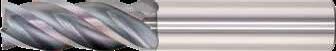
• Excels in advanced axial workpiece entry techniques, including plunging, ramping, and helical interpolation
• Variable helix, rake, and flute indexing eliminates harmonics, suppresses chatter, produces ideal chip shape, and controls cutting zone temperature
• End teeth wiper flat increases corner strength and significantly improves workpiece floor surface finish
• Enhanced corner geometry with tight tolerance corner radii
• Recommended for materials ≤ 45 HRc (≤ 420 Bhn)
3/4 2-1/2 1/4 0.030 39819
5/16 13/16 2-1/2 5/16 – 39821
5/16 13/16 2-1/2 5/16 0.015 39823
5/16 13/16 2-1/2 5/16 0.020 39825
5/16 13/16 2-1/2 5/16 0.030 39827
3/8 5/8 2 3/8 0.020 39839
39822
39824
39826
3/8 7/8 2-1/2 3/8 – 39830 39831 39828 39829 3/8 7/8 2-1/2 3/8 0.010 39833
3/8 7/8 2-1/2 3/8 0.015 39835
39832
39834
3/8 7/8 2-1/2 3/8 0.020 39840 39841 39837 39838
3/8 7/8 2-1/2 3/8 0.030 39844 39845 39842 39843
3/8 7/8 2-1/2 3/8 0.060 39848 39849 39846 39847
7/16 1 2-3/4 7/16 – 39851
7/16 1 2-3/4 7/16 0.020 39853
39850
on next page
TOLERANCES (inch)
1/4 DIAMETER
DC = +0.0000/–0.0012 DCON = h 6 RE = +0.0000/–0.0020
>1/4–3/8 DIAMETER
DC = +0.0000/–0.0016
DCON = h 6
RE = +0.0000/–0.0020
>3/8–3/4 DIAMETER
DC = +0.0000/–0.0020
DCON = h 6
RE = +0.0000/–0.0020
TOLERANCES (inch)
1/4 DIAMETER
DC = +0.0000/–0.0012
DCON = h 6
RE = +0.0000/–0.0020
>1/4–3/8 DIAMETER
DC = +0.0000/–0.0016
DCON = h 6
RE = +0.0000/–0.0020
>3/8–3/4 DIAMETER
DC = +0.0000/–0.0020
DCON = h 6
RE = +0.0000/–0.0020
STAINLESS
Z-Carb-XPR
CARBON STEELS
1018, 1040, 1080, 1090, 10L50, 1140, 1212, 12L15, 1525, 1536
275 Bhn or
28 HRc
ALLOY STEELS
4140, 4150, 4320, 5120, 5150, 8630, 86L20, 50100
375 Bhn or ≤ 40 HRc
TOOL STEELS
A2, D2, H13, L2, M2, P20, S7, T15, W2
STAINLESS STEELS (FREE MACHINING)
303, 416, 420F, 430F, 440F
STAINLESS STEELS (DIFFICULT)
304, 304L, 316, 316L
275 Bhn or ≤ 28 HRc
STEELS (PH)
PH, 15-5PH, 17-4 PH, CUSTOM 450
275 Bhn or ≤ 28 HRc
Continued on next page
CAST IRONS (LOW & MEDIUM ALLOY)
Gray, Malleable, Ductile
CAST IRONS (HIGH ALLOY) Gray, Malleable, Ductile
SUPER ALLOYS (NICKEL , COBALT, IRON BASE)
Inconel 601, 617, 625, Incoloy, Monel 400
SUPER ALLOYS (NICKEL, COBALT, IRON BASE)
Inconel 718, X-750, Incoloy, Waspaloy, Hastelloy, Rene
TITANIUM ALLOYS
Pure Ttanium, Ti6Al4V, Ti6Al2Sn4Zr2Mo, Ti4Al4Mo2Sn0.5Si
TITANIUM ALLOYS (DIFFICULT)
Ti10Al2Fe3Al, Ti5Al5V5Mo3Cr, Ti7Al4Mo, Ti3Al8V6Cr4Zr4Mo, Ti6Al6V6Sn, Ti15V3 Cr3Sn3Al
Bhn (Brinell) HRc (Rockwell C)
rpm = Vc x 3.82 / DC
ipm = Fz x 4 x rpm reduce speed and feed for materials harder than listed reduce feed and Ae when finish milling (.02 x DC maximum) refer to the KYOCERA SGS APEX for complete technical information (www.kyocera-sgstool.com/apex)
• Excels in advanced axial workpiece entry techniques, including plunging, ramping, and helical interpolation
• Variable helix, rake, and flute indexing eliminates harmonics, suppresses chatter, produces ideal chip shape, and controls cutting zone temperature
• End teeth wiper flat increases corner strength and significantly improves workpiece floor surface finish
• Enhanced corner geometry with tight tolerance corner radii
• Recommended for materials ≤ 45 HRc (≤ 420 Bhn)
TOLERANCES (mm)
6 DIAMETER
DC = +0,000/–0,030
= h 6
= +0,000/–0,050
>6–10 DIAMETER
DC = +0,000/–0,040
DCON = h 6
RE = +0,000/–0,050
>10–25 DIAMETER
DC = +0,000/–0,050
DCON = h 6
RE = +0,000/–0,050
CARBON STEELS
1018, 1040, 1080, 1090, 10L50, 1140, 1212, 12L15, 1525, 1536
ALLOY STEELS
4140, 4150, 4320, 5120, 5150, 8630, 86L20, 50100
TOOL STEELS
A2, D2, H13, L2, M2, P20, S7, T15, W2
375 Bhn or
40 HRc
STAINLESS STEELS (FREE MACHINING)
STAINLESS STEELS (DIFFICULT)
304, 304L, 316, 316L
CAST IRONS (LOW & MEDIUM ALLOY)
Gray, Malleable, Ductile
CAST IRONS (HIGH ALLOY)
Gray, Malleable, Ductile
SUPER ALLOYS (NICKEL , COBALT, IRON BASE)
Inconel 601, 617, 625, Incoloy, Monel 400
SUPER ALLOYS (NICKEL, COBALT, IRON BASE)
Inconel 718, X-750, Incoloy, Waspaloy, Hastelloy, Rene
TITANIUM ALLOYS
Pure Ttanium, Ti6Al4V, Ti6Al2Sn4Zr2Mo, Ti4Al4Mo2Sn0.5Si
350 Bhn or ≤ 38 HRc
TITANIUM ALLOYS (DIFFICULT)
Ti10Al2Fe3Al, Ti5Al5V5Mo3Cr, Ti7Al4Mo, Ti3Al8V6Cr4Zr4Mo, Ti6Al6V6Sn, Ti15V3 Cr3Sn3Al
Bhn (Brinell) HRc (Rockwell C) rpm = Vc x 3.82 / DC ipm = Fz x 4 x rpm reduce speed and feed for materials harder than listed reduce feed and Ae when finish milling (.02 x DC maximum) refer to the KYOCERA SGS APEX for complete technical information (www.kyocera-sgstool.com/apex)


TOLERANCES (inch)
≤1/8 DIAMETER
DC = +0.0005/–0.0005
DCON = h 6
RE = +0.000/–0.0010
>1/8–1/4 DIAMETER
DC = +0.000/–0.0012
DCON = h 6
RE = +0.000/–0.0020
>1/4–3/8 DIAMETER
DC = +0.000/–0.0016
DCON = h 6
RE = +0.000/–0.0020
>3/8–1 DIAMETER
DC = +0.000/–0.0020
DCON = h 6
RE = +0.000/–0.0020
*Variable flute spacing. Helix and rake do not vary.

• Variable rake geometry alters and controls the cutting dynamic taking chatter suppression to an unprecedented level
• Unequal helix design changes the cutting angle to improve harmonics
• Unequal flute spacing helps to disrupt the rhythmic pattern created by the cutting edge helping to suppress damaging harmonics
• Enhanced corner geometry with tight tolerance corner radii
• Recommended for materials ≤ 45 HRc (≤ 420 Bhn)
Z-Carb-AP
Z1PCR • Z1P FRACTIONAL SERIES
3/8 7/8 2-1/2 3/8 0.060 36727 36738 –13/32 15/16 2-3/4 7/16 – 36426 36531 –7/16 5/8 2-1/2 7/16 0.020 36515 – –7/16 1 2-3/4 7/16 – 36428
5/8 2-1/2 1/2 0.030
= +0.000/–0.0012
= h 6
>1/4–3/8 DIAMETER
= +0.000/–0.0016 DCON = h 6
= +0.000/–0.0020
>3/8–1 DIAMETER
= +0.000/–0.0020 DCON = h 6
= +0.000/–0.0020
Z-Carb-AP
TOLERANCES (inch)
≤1/8 DIAMETER
DC = +0.0005/–0.0005
DCON = h 6
RE = +0.000/–0.0010
>1/8–1/4 DIAMETER
DC = +0.000/–0.0012
DCON = h 6
RE = +0.000/–0.0020
>1/4–3/8 DIAMETER
DC = +0.000/–0.0016
DCON = h 6
RE = +0.000/–0.0020
>3/8–1 DIAMETER
DC = +0.000/–0.0020
DCON = h 6
RE = +0.000/–0.0020
Z1PCR • Z1P FRACTIONAL SERIES
• Variable rake geometry alters and controls the cutting dynamic taking chatter suppression to an unprecedented level
• Unequal helix design changes the cutting angle to improve harmonics
• Unequal flute spacing helps to disrupt the rhythmic pattern created by the cutting edge helping to suppress damaging harmonics
• Enhanced corner geometry with tight tolerance corner radii
• Recommended for materials ≤ 45 HRc (≤ 420 Bhn)
Z-Carb-AP

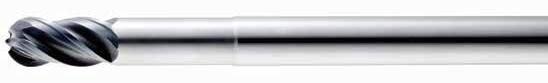
• Variable rake geometry alters and controls the cutting dynamic taking chatter suppression to an unprecedented level
• Unequal helix design reduces damaging harmonics by changing the angle at which each cutting edge enters and exits the material
• Unequal flute spacing helps to disrupt the rhythmic pattern created by the cutting edge helping to suppress damaging harmonics
• Optimal material removal rates through increased feed and depths of cut
• Ball end design ideal for finishing operations in complex workpieces
• Recommended for materials ≤ 45 HRc (≤ 420 Bhn)
DIAMETER
>3/8–1 DIAMETER
= +0.0000/–0.0020
= h 6

TOLERANCES (inch)
1/4 DIAMETER
DC = +0.0000/–0.0012
DCON = h 6
RE = +0.000/–0.005
>1/4–3/8 DIAMETER
DC = +0.0000/–0.0016
DCON = h 6
RE = +0.000/–0.005
>3/8–1 DIAMETER
DC = +0.0000/–0.0020
DCON = h 6
RE = +0.000/–0.005
STAINLESS STEELS
CAST
• Variable rake geometry alters and controls the cutting dynamic taking chatter suppression to an unprecedented level
• Unequal helix design changes the cutting angle to improve harmonics
• Unequal flute spacing helps to disrupt the rhythmic pattern created by the cutting edge helping to suppress damaging harmonics
• Long reach design allows for deeper and faster cuts
• Enhanced corner geometry with tight tolerance corner radii
• Recommended for materials ≤ 45 HRc (≤ 420 Bhn)
Z-Carb-AP
Z1PLB
FRACTIONAL SERIES
• Variable rake geometry alters and controls the cutting dynamic taking chatter suppression to an unprecedented level
• Unequal helix design changes the cutting angle to improve harmonics
• Long reach design allows for deeper and faster cuts
• Ball end design ideal for finishing operations in complex workpieces
• Recommended for materials ≤ 45 HRc (≤ 420 Bhn)
Series Z1P, Z1PCR, Z1PLC, Z1PB, Z1PLB Fractional
CARBON STEELS
1018, 1040, 1080, 1090, 10L50, 1140, 1212, 12L15, 1525, 1536
ALLOY STEELS
4140, 4150, 4320, 5120, 5150, 8630, 86L20, 50100
TOOL STEELS
A2, D2, H13, L2, M2, P20, S7, T15, W2
STAINLESS STEELS (FREE MACHINING)
303, 416, 420F, 430F, 440F
STAINLESS STEELS (PH) 13-8 PH, 15-5 PH, 17-4 PH, Custom 450
Z-Carb-AP
Series Z1P, Z1PCR, Z1PLC, Z1PB, Z1PLB
CAST IRONS (LOW & MEDIUM ALLOY)
Ductile
CAST IRONS (HIGH ALLOY)
Malleable, Ductile
HIGH TEMP ALLOYS (NICKEL, COBALT, IRON BASE)
Inconel 601, 617, 625, Incoloy, Monel 400
HIGH TEMP ALLOYS
(NICKEL, COBALT, IRON BASE)
Inconel 718, X-750, Incoloy, Waspaloy, Hastelloy, Rene
TITANIUM ALLOYS
Pure Titanium, Ti6Al4V, Ti6Al2Sn4Zr2Mo, Ti4Al4Mo2Sn0.5Si
TITANIUM ALLOYS (DIFFICULT)
Ti10V2Fe3Al, Ti5Al5V5Mo3Cr, Ti7Al4Mo, Ti3Al8V6Cr4Zr4Mo, Ti6Al6V6Sn, Ti15V3 Cr3Sn3Al
350 Bhn or ≤ 38 HRc
Bhn (Brinell) HRc (Rockwell C)
rpm = Vc x 3.82 / DC ipm = Fz x 4 x rpm
maximum Slotting Ap for Z1PCR <1/8 diameter and all Z1PLC / Z1PLB is .25 x DC
maximum Profile Ae for Z1PCR <1/8 diameter and all Z1PLC / Z1PLB is .20 x DC reduce speed and feed for materials harder than listed reduce feed and Ae when finish milling (.02 x DC maximum) feed rates listed have chip thinning adjustments included where applicable refer to the KYOCERA SGS APEX for complete technical information (www.kyocera-sgstool.com/apex)
TOLERANCES (mm)
<3 DIAMETER
DC = +0,012/–0,012
DCON = h 6
RE = +0,000/–0,025
>3–6 DIAMETER
DC = +0,000/–0,030
DCON = h 6
RE = +0,000/–0,050
>6–10 DIAMETER
DC = +0,000/–0,040
DCON = h 6
RE = +0,000/–0,050
>10–25 DIAMETER
DC = +0,000/–0,050
DCON = h 6
RE = +0,000/–0,050
STEELS
STAINLESS STEELS
CAST IRON
HIGH TEMP ALLOYS
*Variable flute spacing. Helix and rake do not vary.
Z-Carb-AP
• Variable rake geometry alters and controls the cutting dynamic taking chatter suppression to an unprecedented level
• Unequal helix design changes the cutting angle to improve harmonics
• Unequal flute spacing helps to disrupt the rhythmic pattern created by the cutting edge helping to suppress damaging harmonics
• Enhanced corner geometry with tight tolerance corner radii
• Recommended for materials ≤ 45 HRc (≤ 420 Bhn)
20,0 38,0 104,0 20,0 3,0 42722 46926 42723
20,0 38,0 104,0 20,0 4,0 46868 46945 –20,0 38,0 104,0 20,0 5,0 46869 46946 –
25,0 38,0 104,0 25,0 – 46376 – 46510
25,0 38,0 104,0 25,0 1,0 46866 46927 46498
TOLERANCES (mm)
<3 DIAMETER
= +0,012/–0,012
= h 6
= +0,000/–0,025
>3–6 DIAMETER
= +0,000/–0,030
= h 6
= +0,000/–0,050
>6–10 DIAMETER
= +0,000/–0,040
= h 6
= +0,000/–0,050
>10–25 DIAMETER
= +0,000/–0,050
= h 6
= +0,000/–0,050
TOLERANCES (mm)
3–6 DIAMETER
DC = +0,000/–0,030
DCON = h 6
RE = +0,000/–0,015
>6–10 DIAMETER
DC = +0,000/–0,040
DCON = h 6
RE = +0,000/–0,020
>10–25 DIAMETER
DC = +0,000/–0,050
DCON = h 6
RE = +0,000/–0,025
DC = +0,000/–0,050
DCON = h 6
RE = +0,000/–0,050
STEELS
STAINLESS STEELS
CAST IRON
HIGH TEMP ALLOYS
• Variable rake geometry alters and controls the cutting dynamic taking chatter suppression to an unprecedented level
• Unequal helix design reduces damaging harmonics by changing the angle at which each cutting edge enters and exits the material
• Unequal flute spacing helps to disrupt the rhythmic pattern created by the cutting edge helping to suppress damaging harmonics
• Optimal material removal rates through increased feed and depths of cut
• Ball end design ideal for finishing operations in complex workpieces
• Recommended for materials ≤ 45 HRc (≤ 420 Bhn)
Z-Carb-AP
• Variable rake geometry alters and controls the cutting dynamic taking chatter suppression to an unprecedented level
• Unequal helix design changes the cutting angle to improve harmonics
• Unequal flute spacing helps to disrupt the rhythmic pattern created by the cutting edge helping to suppress damaging harmonics
• Long reach design allows for deeper and faster cuts
• Enhanced corner geometry with tight tolerance corner radii
• Recommended for materials ≤ 45 HRc (≤ 420 Bhn)
+0,000/–0,050 >6–10 DIAMETER
DIAMETER
= h 6
= +0,000/–0,050
Series
Z1MP, Z1MPB, Z1MPCR, Z1MPIC, Z1MPLC Metric Hardness
CARBON STEELS
1018, 1040, 1080, 1090, 10L50, 1140, 1212, 12L15, 1525, 1536
ALLOY STEELS
4140, 4150, 4320, 5120, 5150, 8630, 86L20, 50100
28
TOOL STEELS
A2, D2, H13, L2, M2, P20, S7, T15, W2
Bhn or ≤ 40 HRc
STAINLESS STEELS (FREE MACHINING)
303, 416, 420F, 430F, 440F
METRIC Z-Carb-AP
Series Z1MP, Z1MPB, Z1MPCR, Z1MPIC, Z1MPLC
K CAST IRONS (LOW & MEDIUM ALLOY)
Ductile
CAST IRONS (HIGH ALLOY)
Gray, Malleable, Ductile
HIGH TEMP ALLOYS (NICKEL, COBALT, IRON BASE)
Inconel 601, 617, 625, Incoloy, Monel 400
HIGH TEMP ALLOYS
(NICKEL, COBALT, IRON BASE)
Inconel 718, X-750, Incoloy, Waspaloy, Hastelloy, Rene
32
TITANIUM ALLOYS
Pure Titanium, Ti6Al4V, Ti6Al2Sn4Zr2Mo, Ti4Al4Mo2Sn0.5Si
Bhn or ≤ 38 HRc
TITANIUM ALLOYS (DIFFICULT)
Ti10V2Fe3Al, Ti5Al5V5Mo3Cr, Ti7Al4Mo, Ti3Al8V6Cr4Zr4Mo, Ti6Al6V6Sn, Ti15V3 Cr3Sn3Al
Bhn (Brinell) HRc (Rockwell C) rpm = (Vc x 1000) / (DC x 3.14) mm/min = Fz x 4 x rpm
maximum Slotting Ap for Z1PCR <3mm diameter and all Z1MPLC / Z1MPLB is .25 x DC
maximum Profile Ae for Z1PCR <3mm diameter and all Z1MPLC / Z1MPLB is .20 x DC reduce speed and feed for materials harder than listed reduce feed and Ae when finish milling (.02 x DC maximum) feed rates listed have chip thinning adjustments included where applicable refer to the KYOCERA SGS APEX for complete technical information (www.kyocera-sgstool.com/apex)


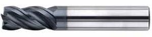
TOLERANCES (inch)
1/4 DIAMETER
DC = +0.0000/–0.0012
DCON = h 6
RE = +0.0000/–0.0020
>1/4–3/8 DIAMETER
DC = +0.0000/–0.0016
DCON = h 6
RE = +0.0000/–0.0020
>3/8–1 DIAMETER
DC = +0.0000/–0.0020
DCON = h 6
RE = +0.0000/–0.0020
• The original Z-Carb design with an enhanced core and higher helix suited for the demands of high temperature alloys
• Unequal flute spacing helps to disrupt the rhythmic pattern created by the cutting edge helping to suppress damaging harmonics
• Optimal material removal rates through increased feed and depths of cut for difficult to machine materials
• Enhanced corner geometry with tight tolerance corner radii
• Recommended for materials ≤ 45 HRc (≤ 420 Bhn)
Z-Carb-HTA
HIGH TEMP ALLOYS
(NICKEL, COBALT, IRON BASE)
Inconel 601, 617, 625, Incoloy, Monel 400
HIGH TEMP ALLOYS (NICKEL, COBALT, IRON BASE)
Inconel 718, X-750, Incoloy, Waspaloy, Hastelloy, Rene
TITANIUM ALLOYS
Pure Titanium, Ti6Al4V, Ti6Al2Sn4Zr2Mo, Ti4Al4Mo2Sn0.5Si
350 Bhn or
38 HRc
TITANIUM ALLOYS (DIFFICULT)
Ti10V2Fe3Al, Ti5Al5V5Mo3Cr, Ti7Al4Mo, Ti3Al8V6Cr4Zr4Mo, Ti6Al6V6Sn, Ti15V3 Cr3Sn3Al ≤ 420 Bhn or ≤ 45 HRc
Bhn (Brinell) HRc (Rockwell C) rpm = Vc x 3.82 / DC ipm = Fz x 4 x rpm reduce speed and feed for materials harder than listed reduce feed and Ae when finish milling (.02 x DC maximum) feed rates listed have chip thinning adjustments included where applicable refer to the KYOCERA SGS APEX for complete technical information (www.kyocera-sgstool.com/apex)
TOLERANCES (mm)
6 DIAMETER
DC = +0,000/–0,030
DCON = h 6
RE = +0,000/–0,050
>6–10 DIAMETER
DC = +0,000/–0,040
DCON = h 6
RE = +0,000/–0,050
>10–20 DIAMETER
DC = +0,000/–0,050
DCON = h 6
RE = +0,000/–0,050
• The original Z-Carb design with an enhanced core and higher helix suited for the demands of high temperature alloys
• Unequal flute spacing helps to disrupt the rhythmic pattern created by the cutting edge helping to suppress damaging harmonics
• Optimal material removal rates through increased feed and depths of cut for difficult to machine materials
• Enhanced corner geometry with tight tolerance corner radii
• Recommended for materials ≤ 45 HRc (≤ 420 Bhn)
Z-Carb-HTA
HIGH TEMP ALLOYS
(NICKEL, COBALT, IRON BASE)
Inconel 601, 617, 625, Incoloy, Monel 400
HIGH TEMP ALLOYS (NICKEL, COBALT, IRON BASE)
Inconel 718, X-750, Incoloy, Waspaloy, Hastelloy, Rene
32 HRc
TITANIUM ALLOYS
Pure Titanium, Ti6Al4V, Ti6Al2Sn4Zr2Mo, Ti4Al4Mo2Sn0.5Si
43 HRc
TITANIUM ALLOYS (DIFFICULT)
Ti10V2Fe3Al, Ti5Al5V5Mo3Cr, Ti7Al4Mo, Ti3Al8V6Cr4Zr4Mo, Ti6Al6V6Sn, Ti15V3 Cr3Sn3Al ≤ 420 Bhn or ≤ 45 HRc
Bhn (Brinell) HRc (Rockwell C) rpm = (Vc x 1000) / (DC x 3.14) ipm = Fz x 4 x rpm reduce speed and feed for materials harder than listed reduce feed and Ae when finish milling (.02 x DC maximum) feed rates listed have chip thinning adjustments included where applicable refer to the KYOCERA SGS APEX for complete technical information (www.kyocera-sgstool.com/apex)


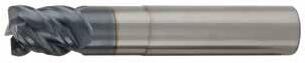
TOLERANCES (inch)
1/8–1/4 DIAMETER
DC = +0.0000/–0.0012
DCON = h 6
RE = +0.0000/–0.0020
>1/4–3/8 DIAMETER
DC = +0.0000/–0.0016
DCON = h 6
RE = +0.0000/–0.0020
>3/8–3/4 DIAMETER
DC = +0.0000/–0.0020
DCON = h 6
RE = +0.0000/–0.0020
STEELS
HARDENED STEELS
• The original Z-Carb design with negative rake, heavy core, and higher helix for strength and shearing of hard mold & die materials
• Unequal flute spacing helps to disrupt the rhythmic pattern created by the cutting edge helping to suppress damaging harmonics
• Enhanced corner geometry with tight tolerance corner radii
• Recommended for materials 35-60HRc (327 to 654 Bhn)
TOLERANCES (mm)
3–6 DIAMETER
DC = +0,000/–0,030
DCON = h 6
RE = +0,000/–0,050
>6–10 DIAMETER
DC = +0,000/–0,040
DCON = h 6
RE = +0,000/–0,050
>10–20 DIAMETER
DC = +0,000/–0,050
DCON = h 6
RE = +0,000/–0,050
• The original Z-Carb design with negative rake, heavy core, and higher helix for strength and shearing of hard mold & die materials
• Unequal flute spacing helps to disrupt the rhythmic pattern created by the cutting edge helping to suppress damaging harmonics
• Enhanced corner geometry with tight tolerance corner radii
• Recommended for materials 35-60HRc (327 to 654 Bhn)
P
Series ZD1CR Fractional Hardness
TOOL STEELS
A2, D2, H13, L2, M2, P20, S7, T15, W2 ≤ 375 Bhn or ≤
TOOL STEELS
A2, D2, H13, L2, M2, P20, S7, T15, W2
TOOL STEELS
A2, D2, H13, L2, M2, P20, S7, T15, W2
Bhn (Brinell) HRc (Rockwell C)
rpm = Vc x 3.82 / DC
ipm = Fz x 4 x rpm reduce speed and feed for materials harder than listed reduce feed and Ae when finish milling (.02 x DC maximum) feed rates listed have chip thinning adjustments included where applicable refer to the KYOCERA SGS APEX for complete technical information (www.kyocera-sgstool.com/apex)
TOOL STEELS
A2, D2, H13, L2, M2, P20, S7, T15, W2
Bhn (Brinell) HRc (Rockwell C)
rpm = (Vc x 1000) / (DC x 3.14)
ipm = Fz x 4 x rpm reduce speed and feed for materials harder than listed reduce feed and Ae when finish milling (.02 x DC maximum) feed rates listed have chip thinning adjustments included where applicable refer to the KYOCERA SGS APEX for complete technical information (www.kyocera-sgstool.com/apex)
TOOL STEELS A2,
TOOL STEELS


TOLERANCES (inch)
1/8–1/4 DIAMETER
DC = +0.0000/–0.0012
DCON = h 6
RE = +0.0000/–0.0020
>1/4–3/8 DIAMETER
DC = +0.0000/–0.0016
DCON = h 6
RE = +0.0000/–0.0020
>3/8–1 DIAMETER
DC = +0.0000/–0.0020
DCON = h 6
RE = +0.0000/–0.0020
1/8 3/8 1-1/2 1/8 .010 .044 38775 –
1/8 3/8 1-1/2 1/8 .015 .044 37181 – –
3/8
3/8
1/8 3/8 2 1/8
3/16 5/16 2 3/16 .010 .066
3/16 5/16 2 3/16 .015 .066 38526
3/16 5/16 2 3/16 .030 .066 38781
1/2
3/16 1/2 2 3/16 .010 .066 38783
3/16 1/2 2 3/16 .015 .066 37183
3/16 1/2 2 3/16 .030 .066 38785 –
3/16 9/16 2-1/2 3/16 – .066 37406 37407
3/16 9/16 2-1/2 3/16 .010 .066 37410 37411
3/16 9/16 2-1/2 3/16 .015 .066 37414 37415
3/16 9/16 2-1/2 3/16 .030
1/4 3/8 2-1/2

• An ideal balance of helix, indexing, flute depth, rake and relief
• Variable indexing for chatter supression and patented edge geometry for shearing and strength
• Chatter-free geometry allows deep cutting and high speed machining
• Central coolant hole delivers coolant effectively to the cutting zone enhancing chip removal when pocketing or slotting
• Excels at roughing, ramping, high speed machining and finishing in a variety of materials
• Enhanced corner geometry with tight tolerance corner radii
• Recommended for materials ≤ 45 HRc (≤ 420 Bhn)
STEELS
STAINLESS STEELS
CAST IRON
HIGH TEMP ALLOYS
1/4 1/2 2-1/2 1/4 .010 .088 38793
1/4 1/2 2-1/2 1/4 .015 .088 37185
1/4 1/2 2-1/2 1/4 .030 .088 37186
1/4 1/2 2-1/2 1/4 .060 .075 38795
1/4 3/4 2-1/2 1/4
1/4 3/4 2-1/2 1/4 .010 .088 37426 37427
1/4 3/4 2-1/2 1/4 .015 .088 37430 37431
1/4 3/4 2-1/2 1/4 .030 .088 37434 37435
1/4 3/4 2-1/2 1/4 .060 .088 37438 37439
5/16 7/16 2-1/2 5/16 – .109 38503
5/16 7/16 2-1/2 5/16 .010 .109 38799
5/16 7/16 2-1/2 5/16 .015 .109 38529
5/16 7/16 2-1/2 5/16 .030 .109 38801
5/16 7/16 2-1/2 5/16 .060 .109 38803
5/16 7/16 2-1/2 5/16 .090 .064 38805
5/16 5/8 2-1/2 5/16 – .109 38504
5/16 5/8 2-1/2 5/16 .010 .109 38807
5/16 5/8 2-1/2 5/16 .015 .109 38530
5/16 5/8 2-1/2 5/16 .030 .109 38809
5/16 5/8 2-1/2 5/16 .060 .109 38811
5/16 5/8 2-1/2 5/16 .090 .064 38813
5/16 15/16 3 5/16 – .109 37446 37447
5/16 15/16 3 5/16
5/16 15/16 3 5/16
5/16 15/16 3 5/16 .030
1/8–1/4
>1/4–3/8 DIAMETER
+0.0000/–0.0016
>3/8–1 DIAMETER
= +0.0000/–0.0020 DCON = h 6
= +0.0000/–0.0020
continued on next page
TOLERANCES (inch)
1/8–1/4 DIAMETER
DC = +0.0000/–0.0012
DCON = h 6
RE = +0.0000/–0.0020
>1/4–3/8 DIAMETER
DC = +0.0000/–0.0016
DCON = h 6
RE = +0.0000/–0.0020
>3/8–1 DIAMETER
DC = +0.0000/–0.0020
DCON = h 6
RE = +0.0000/–0.0020
3/8
3/8 3/4 2-1/2
3/8 3/4 2-1/2 3/8 .015 .131
3/8 3/4
3/8
3/8 1-1/8 3 3/8 – .131 37470 37471
3/8 1-1/8 3 3/8 .010 .131 37474 37475
3/8
3/8 1-1/8 3 3/8 .060 .131 37486 37487
3/8 1-1/8 3 3/8 .090 .083 37490 37491
7/16 5/8 2-1/2 7/16 .015 .153 37164
7/16 5/8 2-1/2 7/16 .030 .153 37165 –
7/16 7/8 2-3/4 7/16 .015 .153 37166 –
7/16 7/8 2-3/4 7/16 .030 .153 37167 –
7/16 1-5/16 3 7/16 – .153 37494 37495
7/16 1-5/16 3 7/16 .015 .153 37498 37499 –
7/16 1-5/16 3 7/16 .030 .153 37502 37503 –
1/2 5/8 3 1/2 – .175 38506 – 37320
1/2 5/8 3
1/2 5/8 3
Z-Carb-HPR
STAINLESS STEELS
CAST IRON
HIGH TEMP ALLOYS
1/2 1-1/4 3-1/4 1/2 .090 .175
1/2 1-1/4 3-1/4 1/2 .120 .175
1/2 1-1/2 3-1/2 1/2 – .175 37506 37508 37507
1/2 1-1/2 3-1/2 1/2 .015 .175
1/2 1-1/2 3-1/2 1/2 .030 .175
1/2 1-1/2 3-1/2 1/2 .060 .175
1/2 1-1/2 3-1/2 1/2 .090 .175 37546 37548
1/2 1-1/2 3-1/2 1/2 .120 .175 37554 37556 37555
5/8 3/4 3-1/2 5/8 – .219 38508 –
1/8–1/4
>1/4–3/8 DIAMETER
>3/8–1 DIAMETER
= +0.0000/–0.0020
DCON = h 6
= +0.0000/–0.0020
5/8 3/4 3-1/2 5/8 .010 .219 38845 – 38849 – 38847 38844 – 38848 – 38846
5/8 3/4 3-1/2 5/8 .015 .219 38545 – 38623 – 38590 37061 – 37261 – 37068
5/8 3/4 3-1/2 5/8
5/8 3/4 3-1/2 5/8 .090 .219 38548 – 38626 – 38593 37064 – 37264 –
5/8 3/4 3-1/2 5/8 .120 .219 38549 – 38627 – 38594 37065
5/8
continued on next page
TOLERANCES (inch)
1/8–1/4 DIAMETER
DC = +0.0000/–0.0012
DCON = h 6
RE = +0.0000/–0.0020
>1/4–3/8 DIAMETER
DC = +0.0000/–0.0016
DCON = h 6
RE = +0.0000/–0.0020
>3/8–1 DIAMETER
DC = +0.0000/–0.0020
DCON = h 6
RE = +0.0000/–0.0020
5/8 1-1/4 3-1/2 5/8 .015 .219 37199 –
5/8 1-1/4
5/8 1-1/4 3-1/2 5/8 .060 .219 37201 – 38631 – 37205 37077 – 37270 –
5/8 1-1/4 3-1/2 5/8 .090 .219 38551 – 38632 – 38596 37078 – 37271 – 37085 – –
5/8 1-1/4 3-1/2 5/8 .120 .219 38552 – 38633 – 38597 37079 – 37272 –
5/8 1-1/4 3-1/2 5/8 .190 .219 38553 – 38634 – 38598 37080 – 37273 – 37087 – –
5/8 1-7/8 4 5/8 – .219 37562 37564 37563 37565 –
5/8 1-7/8 4 5/8 .010 .219 37570 37572 37571 37573 – 37574
5/8
5/8 1-7/8 4 5/8 .030 .219
5/8 1-7/8 4 5/8 .060 .219
5/8 1-7/8 4 5/8 .090 .219
5/8 1-7/8 4
5/8 1-7/8 4 5/8 .190 .219 37618 37620 37619 37621 –
3/4 7/8 4 3/4 – .263 38509 – 38520 – 38515 37088
3/4 7/8 4 3/4 .010 .263 38857 – 38861 – 38859 38856
3/4 7/8 4 3/4 .030 .263 38554 – 38635 – 38599 37089
3/4 7/8 4 3/4 .060 .263 38555 – 38636 – 38600 37090
3/4 7/8 4 3/4 .090 .263 38556 – 38637 – 38601 37091 – 37277 – 37098 – –
3/4 7/8 4 3/4 .120 .263 38557 – 38638 – 38602 37092 – 37278 – 37099 – –
3/4 7/8 4 3/4 .190 .263 38558 – 38639 – 38603 37093 – 37279 – 37100 – –
3/4 7/8 4 3/4 .250 .263 38559 – 38640 – 38604 37094 – 37280 – 37101 – –
3/4 1-1/2 4 3/4 – .263 37206 – 38521 – 37210 37102 – 37281 – 37109 – –
3/4 1-1/2 4 3/4 .010 .263 38863 – 38867 – 38865 38862 – 38866 – 38864 – –
3/4 1-1/2 4 3/4
3/4 1-1/2 4
3/4
3/4 1-1/2 4
3/4 1-1/2 4
Z-Carb-HPR
STEELS
STAINLESS STEELS
CAST IRON
HIGH TEMP ALLOYS
3/4 1-5/8 4 3/4 .030 .263 37222
3/4 1-5/8 4 3/4 .060 .263
3/4 1-5/8 4 3/4 .090 .263 37226
3/4 1-5/8 4 3/4 .120 .263
3/4 2 4-1/2 3/4 .030 .263
3/4 2 4-1/2 3/4 .060 .263 37232
3/4 2 4-1/2 3/4 .090 .263 37234
3/4 2 4-1/2 3/4 .120 .263 37236
3/4 2-1/4 5 3/4
3/4 2-1/4 5 3/4 .010 .263
1/8–1/4
TOLERANCES (inch)
1/8–1/4 DIAMETER
DC = +0.0000/–0.0012
DCON = h 6
RE = +0.0000/–0.0020
>1/4–3/8 DIAMETER
DC = +0.0000/–0.0016
DCON = h 6
RE = +0.0000/–0.0020
>3/8–1 DIAMETER
DC = +0.0000/–0.0020
DCON = h 6
RE = +0.0000/–0.0020
Z-Carb-HPR
Z5L • Z5LCR
FRACTIONAL SERIES
• An ideal balance of helix, indexing, flute depth, rake and relief
• Variable indexing for chatter supression and patented edge geometry for shearing and strength
• Chatter-free geometry allows deep cutting and high speed machining
• Central coolant hole delivers coolant effectively to the cutting zone enhancing chip removal when pocketing or slotting
• Excels at roughing, ramping, high speed machining and finishing in a variety of materials
• Enhanced corner geometry with tight tolerance corner radii
• Recommended for materials ≤ 45 HRc (≤ 420 Bhn)
STEELS
STAINLESS STEELS
CAST IRON
HIGH TEMP ALLOYS
TOLERANCES (inch)
1/8–1/4 DIAMETER
DC = +0.0000/–0.0012
DCON = h 6
RE = +0.0000/–0.0020
>1/4–3/8 DIAMETER
DC = +0.0000/–0.0016
DCON = h 6
RE = +0.0000/–0.0020
>3/8–1 DIAMETER
DC = +0.0000/–0.0020
DCON = h 6
RE = +0.0000/–0.0020
Z-Carb-HPR
Z5CR, Z5L, Z5LC Fractional
CARBON STEELS
1018, 1040, 1080, 1090, 10L50, 1140, 1212, 12L15, 1525, 1536
P
ALLOY STEELS
4140, 4150, 4320, 5120, 5150, 8630, 86L20, 50100
STAINLESS
M
HIGH TEMP ALLOYS
SUPER ALLOYS (NICKEL, COBALT, IRON BASE)
Inconel 718, X-750, Incoloy, Waspaloy, Hastelloy, Rene
TITANIUM ALLOYS
Pure Ttanium, Ti6Al4V, Ti6Al2Sn4Zr2Mo, Ti4Al4Mo2Sn0.5Si
Ti10Al2Fe3Al, Ti5Al5V5Mo3Cr, Ti7Al4Mo, Ti3Al8V6Cr4Zr4Mo, Ti6Al6V6Sn, Ti15V3 Cr3Sn3Al
Bhn (Brinell) HRc (Rockwell C) HSM (High Speed Machining)
rpm = Vc x 3.82 / DC
ipm = Fz x 5 x rpm
1 HSM method strongly recommended, particularly when using 4 x DC tools
2 reduce Ap to ≤.5 x DC when slotting with 4 x DC tools ramp up to 5 degrees using slotting speed and feed rates. Do not plunge. reduce speed and feed for materials harder than listed reduce feed and Ae when finish milling (.02 x DC maximum) feed rates listed have chip thinning adjustments included where applicable refer to the KYOCERA SGS APEX for complete technical information (www.kyocera-sgstool.com/apex)
Z-Carb-HPR
METRIC SERIES
• An ideal balance of helix, indexing, flute depth, rake and relief
• Variable indexing for chatter supression and patented edge geometry for shearing and strength
• Chatter-free geometry allows deep cutting and high speed machining
• Central coolant hole delivers coolant effectively to the cutting zone enhancing chip removal when pocketing or slotting
• Enhanced corner geometry with tight tolerance corner radii
• Excels at roughing, ramping, high speed machining and finishing in a variety of materials
• Recommended for materials ≤ 45 HRc (≤ 420 Bhn)
STEELS
STAINLESS STEELS
CAST IRON
HIGH TEMP ALLOYS
= h 6
TOLERANCES (mm)
6 DIAMETER
DC = +0,000/–0,030
DCON = h 6
RE = +0,000/–0,050
>6–10 DIAMETER
DC = +0,000/–0,040
DCON = h 6
RE = +0,000/–0,050
>10–25 DIAMETER
DC = +0,000/–0,050
DCON = h 6
RE = +0,000/–0,050
12,0 26,0 83,0 12,0 2,5 4,19 48014 – 47170 48032 47022 – 47171 47030 – –
12,0 36,0 83,0 12,0 1,5 4,19 47544
12,0 36,0 83,0 12,0 2,0 4,19 47548 47549
16,0 19,0 82,0 16,0 1,0 5,59 48016
16,0 19,0 82,0 16,0 1,5 5,59
16,0 35,0 92,0 16,0 1,5 5,59 48017
16,0 35,0 92,0 16,0 2,0 5,59
16,0 35,0 92,0
TOLERANCES (mm)
6 DIAMETER
DC = +0,000/–0,030
DCON = h 6
RE = +0,000/–0,050
>6–10 DIAMETER
DC = +0,000/–0,040
DCON = h 6
RE = +0,000/–0,050
>10–25 DIAMETER
DC = +0,000/–0,050
DCON = h 6
RE = +0,000/–0,050
• An ideal balance of helix, indexing, flute depth, rake and relief
• Variable indexing for chatter supression and patented edge geometry for shearing and strength
• Chatter-free geometry allows deep cutting and high speed machining
• Central coolant hole delivers coolant effectively to the cutting zone enhancing chip removal when pocketing or slotting
• Excels at roughing, ramping, high speed machining and finishing in a variety of materials
• Enhanced corner geometry with tight tolerance corner radii
• Recommended for materials ≤ 45 HRc (≤ 420 Bhn)
Z-Carb-HPR
P
CARBON STEELS
1018, 1040, 1080, 1090, 10L50, 1140, 1212, 12L15, 1525, 1536
ALLOY STEELS
4140, 4150, 4320, 5120, 5150, 8630, 86L20, 50100
TOOL STEELS
A2, D2, H13, L2, M2, P20, S7, T15, W2
STAINLESS STEELS (FREE MACHINING)
303, 416, 420F, 430F, 440F
375 Bhn or ≤ 40 HRc
STAINLESS STEELS (DIFFICULT)
STEELS (PH)
Gray, Malleable, Ductile
K CAST IRONS (LOW & MEDIUM ALLOY)
CAST IRONS (HIGH ALLOY)
Gray, Malleable, Ductile
SUPER ALLOYS (NICKEL , COBALT, IRON BASE)
Inconel 601, 617, 625, Incoloy, Monel 400
SUPER ALLOYS (NICKEL, COBALT, IRON BASE)
Inconel 718, X-750, Incoloy, Waspaloy, Hastelloy, Rene
TITANIUM ALLOYS
Pure Ttanium, Ti6Al4V, Ti6Al2Sn4Zr2Mo, Ti4Al4Mo2Sn0.5Si
TITANIUM ALLOYS (DIFFICULT)
Ti10Al2Fe3Al, Ti5Al5V5Mo3Cr, Ti7Al4Mo, Ti3Al8V6Cr4Zr4Mo, Ti6Al6V6Sn, Ti15V3 Cr3Sn3Al
350 Bhn or ≤ 38 HRc
Bhn (Brinell) HRc (Rockwell C) HSM (High Speed Machining)
rpm = Vc x 1000 / (DC x 3.14)
ipm = Fz x 5 x rpm
1 HSM method strongly recommended, particularly when using 4 x DC tools
2 reduce Ap to ≤.5 x DC when slotting with 4 x DC tools ramp up to 5 degrees using slotting speed and feed rates. Do not plunge. reduce speed and feed for materials harder than listed reduce feed and Ae when finish milling (.02 x DC maximum) feed rates listed have chip thinning adjustments included where applicable refer to the KYOCERA SGS APEX for complete technical information (www.kyocera-sgstool.com/apex)

SERIES
• Unequal indexing, high helix and an ideal rake and relief combination for unmatched finishing capability
• The choice when peak finish quality is the requirement
• Enhanced corner geometry with tight tolerance corner radii
• Recommended for materials ≤ 45 HRc (≤ 420 Bhn)
.015 32612 –7/32 3/4 2-1/2 1/4 .015 32613 –7/32 3/4 2-1/2 1/4 – 32658 –1/4 3/8 2 1/4 .015 32614 –1/4 3/8 2 1/4 – 32674 –1/4 3/4 2-1/2 1/4 – 32659 –1/4 3/4 2-1/2 1/4 .015 32615 –1/4 1-1/4 4 1/4 .015 32616 –5/16 7/16 2 5/16 – 32675 –5/16 7/16 2 5/16 .015 32619 –5/16 13/16 2-1/2 5/16 – 32660 –5/16 13/16 2-1/2 5/16
TOLERANCES (inch) DC = +0.0000/–0.0020 DCON =
3/4 3 5/8 .030 32598 32599
5/8 3/4 3 5/8 .060 32600 32601
5/8 1-5/8 3-1/2 5/8 – 32666 32667
5/8 1-5/8 3-1/2 5/8 .030 32579 32580
5/8 1-5/8 3-1/2 5/8 .060 32581 32582
5/8 2-1/2 5 5/8 .030 32570 –
5/8 2-1/2 5 5/8
55B
FRACTIONAL SERIES
• Unequal indexing, high helix and an ideal rake and relief combination for unmatched finishing capability
• The choice when peak finish quality is the requirement
• Ball end design ideal for finishing operations in complex workpieces
• Recommended for materials ≤ 45 HRc (≤ 420 Bhn)

Series 55, 55CR, 55B Fractional
CARBON STEELS
1018, 1040, 1080, 1090, 10L50, 1140, 1212, 12L15, 1525, 1536
ALLOY STEELS
4140, 4150, 4320, 5120, 5150, 8630, 86L20, 50100
28 HRc
TOOL STEELS
A2, D2, H13, L2, M2, P20, S7, T15, W2
STAINLESS STEELS (FREE MACHINING)
303, 416, 420F, 430F, 440F
375 Bhn or ≤ 40
STAINLESS STEELS (PH) 13-8 PH, 15-5 PH, 17-4 PH, Custom 450
V-Carb
CAST IRONS (LOW & MEDIUM ALLOY) Gray, Malleable, Ductile
K
CAST IRONS (HIGH
HIGH TEMP ALLOYS (NICKEL, COBALT, IRON BASE)
Inconel 601, 617, 625, Incoloy, Monel 400
HIGH TEMP ALLOYS (NICKEL, COBALT, IRON BASE)
Inconel 718, X-750, Incoloy, Waspaloy, Hastelloy, Rene
32 HRc
TITANIUM ALLOYS
Pure Titanium, Ti6Al4V, Ti6Al2Sn4Zr2Mo, Ti4Al4Mo2Sn0.5Si
43
TITANIUM ALLOYS (DIFFICULT)
Ti10V2Fe3Al, Ti5Al5V5Mo3Cr, Ti7Al4Mo, Ti3Al8V6Cr4Zr4Mo, Ti6Al6V6Sn, Ti15V3 Cr3Sn3Al
Bhn (Brinell) HRc (Rockwell C) HSM (High Speed Machining) rpm = Vc x 3.82 / DC ipm = Fz x 5 x rpm reduce speed and feed for materials harder than listed reduce feed and Ae when finish milling (.02 x DC maximum) reduce Ap to 1 x DC (maximum) when profile milling with long or extra long flute length tools feed rates listed have chip thinning adjustments included where applicable refer to the KYOCERA SGS APEX for complete technical information (www.kyocera-sgstool.com/apex)
TOLERANCES (mm) DC = +0,000/–0,050
STEELS
STAINLESS STEELS
CAST IRON
HIGH TEMP ALLOYS
42666 –8,0 20,0 63,0 8,0 – 42610 –8,0 20,0 63,0 8,0 0,5 42667 –8,0 20,0 63,0 8,0 1,0 42668 –8,0 20,0 63,0 8,0 1,5 42669 –8,0 20,0 63,0 8,0 2,0 42670 –8,0 25,0 75,0 8,0 – 42611 –8,0 25,0 75,0 8,0 0,5
• Unequal indexing, high helix and an ideal rake and relief combination for unmatched finishing capability
• The choice when peak finish quality is the requirement
• Enhanced corner geometry with tight tolerance corner radii
• Recommended for materials ≤ 45 HRc (≤ 420 Bhn)
–continued on next page
= +0,000/–0,050
Unequal
TOLERANCES (mm) DC = +0,000/–0,050
= h 6
= +0,000/–0,050
• Unequal indexing, high helix and an ideal rake and relief combination for unmatched finishing capability
• The choice when peak finish quality is the requirement
• Ball end design ideal for finishing operations in complex workpieces
• Recommended for materials ≤ 45 HRc (≤ 420 Bhn)
55M, 55MCR, 55MB
CARBON STEELS
1018, 1040, 1080, 1090, 10L50, 1140, 1212, 12L15, 1525, 1536
ALLOY STEELS
4140, 4150, 4320, 5120, 5150, 8630, 86L20, 50100
275 Bhn or ≤ 28 HRc
TOOL STEELS
A2, D2, H13, L2, M2, P20, S7, T15, W2
375 Bhn or ≤ 40 HRc
STAINLESS STEELS (FREE MACHINING)
303, 416, 420F, 430F, 440F
STAINLESS STEELS (DIFFICULT)
304, 304L, 316, 316L
STAINLESS STEELS (PH)
13-8 PH, 15-5 PH, 17-4 PH, Custom 450
Bhn or
28 HRc
continued on next page
K CAST IRONS (LOW & MEDIUM ALLOY)
S
Malleable, Ductile
S
TEMP
(NICKEL, COBALT, IRON BASE)
Inconel 601, 617, 625, Incoloy, Monel 400
HIGH TEMP ALLOYS
(NICKEL, COBALT, IRON BASE)
Inconel 718, X-750, Incoloy, Waspaloy, Hastelloy, Rene
32
TITANIUM ALLOYS
Pure Titanium, Ti6Al4V, Ti6Al2Sn4Zr2Mo, Ti4Al4Mo2Sn0.5Si
350 Bhn or
38 HRc
TITANIUM ALLOYS (DIFFICULT)
Ti10V2Fe3Al, Ti5Al5V5Mo3Cr, Ti7Al4Mo, Ti3Al8V6Cr4Zr4Mo, Ti6Al6V6Sn, Ti15V3 Cr3Sn3Al
Bhn (Brinell) HRc (Rockwell C) HSM (High Speed Machining) rpm = (Vc x 1000) / (DC x 3.14) mm/min = Fz x 5 x rpm reduce speed and feed for materials harder than listed reduce feed and Ae when finish milling (.02 x DC maximum) reduce Ap to 1 x DC (maximum) when profile milling with long or extra long flute length tools feed rates listed have chip thinning adjustments included where applicable refer to the KYOCERA SGS APEX for complete technical information (www.kyocera-sgstool.com/apex)

• Engineered for High Speed Milling using Trochoidal and Peel Milling techniques
• Eccentric relief provides superior strength and smoother surface finish
• Enhanced corner geometry with tight tolerance corner radii
• Recommended for materials ≤ 45 HRc (≤ 420 Bhn)
35115 1/2 1-1/4 3 1/2 .060 35152 1/2 1-1/4 3 1/2 .090 35116 1/2 1-1/4 3 1/2 .120 35117
5/8 1-5/8 3-1/2 5/8 – 35103
5/8 1-5/8 3-1/2 5/8 .015 35153
5/8 1-5/8 3-1/2 5/8 .030 35118
5/8 1-5/8 3-1/2 5/8 .060 35154
5/8 1-5/8 3-1/2 5/8 .090 35119
5/8 1-5/8 3-1/2 5/8 .120 35120
5/8 1-5/8 3-1/2 5/8 .190 35155
3/4 1-5/8 4 3/4 – 35104
3/4 1-5/8 4 3/4 .030 35121
3/4 1-5/8 4 3/4 .060 35156
3/4 1-5/8 4 3/4 .090 35122
3/4 1-5/8 4 3/4 .120 35123
3/4 1-5/8 4 3/4 .190 35157
3/4 1-5/8 4 3/4 .250 35158 1 2-5/8 6 1 – 35105 1 2-5/8 6 1 .030 35124 1 2-5/8 6 1 .060 35159 1 2-5/8 6 1 .090 35125 1 2-5/8 6 1 .120 35126 1 2-5/8 6 1 .190 35160 1 2-5/8 6 1 .250 35161
TOLERANCES (inch)
STAINLESS STEELS
CAST IRON HIGH TEMP ALLOYS
5/8 3/4 5 5/8
3/4
5/8 3/4 5 5/8
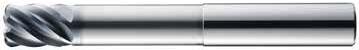
• Engineered for High Speed Milling using Trochoidal and Peel Milling techniques
• Eccentric relief provides superior strength and smoother surface finish
• Necked design with blended diameter transitions provide clearance to reach
• Enhanced corner geometry with tight tolerance corner radii
• Recommended for materials ≤ 45 HRc (≤ 420 Bhn)
T-Carb
51B FRACTIONAL SERIES
• Engineered for High Speed Milling using Trochoidal and Peel Milling techniques
• Faceted relief provides superior strength and smoother surface finish
• Ball end design ideal for finishing operations in complex workpieces
• Recommended for materials ≤ 45 HRc (≤ 420 Bhn)

Cutting Diameter (DC)
51LB
FRACTIONAL SERIES
• Engineered for High Speed Milling using Trochoidal and Peel Milling techniques

• Faceted relief provides superior strength and smoother surface finish
• Ball end design ideal for finishing operations in complex workpieces
• Recommended for materials ≤ 45 HRc (≤ 420 Bhn)
Cutting Diameter (DC)
(inch)
= +0.000/–0.0020
= h 6
Series 51, 51CR, 51L, 51LC, 51B, 51LB Fractional
CARBON STEELS
1018, 1040, 1080, 1090, 10L50, 1140, 1212, 12L15, 1525, 1536
ALLOY STEELS
4140, 4150, 4320, 5120, 5150, 8630, 86L20, 50100
Bhn or ≤ 28 HRc
TOOL STEELS
A2, D2, H13, L2, M2, P20, S7, T15, W2
375 Bhn or
40 HRc
STAINLESS STEELS (FREE MACHINING)
303, 416, 420F, 430F, 440F
STAINLESS STEELS (DIFFICULT)
304, 304L, 316, 316L
275 Bhn or ≤ 28 HRc
continued on next page
Series 51, 51CR, 51L, 51LC, 51B, 51LB Fractional
CAST IRONS (LOW & MEDIUM ALLOY)
Gray, Malleable, Ductile
K
CAST IRONS (HIGH ALLOY)
Gray, Malleable, Ductile
HIGH TEMP ALLOYS (NICKEL, COBALT, IRON BASE)
Inconel 601, 617, 625, Incoloy, Monel 400
HIGH TEMP ALLOYS (NICKEL, COBALT, IRON BASE)
Inconel 718, X-750, Incoloy, Waspaloy, Hastelloy, Rene
32
TITANIUM ALLOYS
Pure Titanium, Ti6Al4V, Ti6Al2Sn4Zr2Mo, Ti4Al4Mo2Sn0.5Si ≤ 350 Bhn or ≤ 38 HRc
TITANIUM ALLOYS (DIFFICULT)
Ti10V2Fe3Al, Ti5Al5V5Mo3Cr, Ti7Al4Mo, Ti3Al8V6Cr4Zr4Mo, Ti6Al6V6Sn, Ti15V3 Cr3Sn3Al
Bhn or ≤ 45 HRc
Bhn (Brinell) HRc (Rockwell C) HSM (High Speed Machining)
rpm = Vc x 3.82 / DC
ipm = Fz x 6 x rpm reduce speed and feed for materials harder than listed reduce feed and Ae when finish milling (.02 x DC maximum) feed rates listed have chip thinning adjustments included where applicable refer to the KYOCERA SGS APEX for complete technical information (www.kyocera-sgstool.com/apex)
TOLERANCES (mm)
DC = +0,000/–0,050
DCON = h 6
RE = +0,000/–0,050
STAINLESS STEELS
CAST IRON
HIGH TEMP ALLOYS
10,0 22,0 75,0 10,0 2,5 45175 12,0 26,0 83,0 12,0 – 45103 12,0 26,0 83,0 12,0 0,5 45176 12,0 26,0 83,0 12,0 0,76 45177
45118
45120
• Engineered for High Speed Milling using Trochoidal and Peel Milling techniques
• Eccentric relief provides superior strength and smoother surface finish
• Enhanced corner geometry with tight tolerance corner radii
• Recommended for materials ≤ 45 HRc (≤ 420 Bhn)
DCON
• Engineered for High Speed Milling using Trochoidal and Peel Milling techniques
• Eccentric relief provides superior strength and smoother surface finish
• Necked design with blended diameter transitions provide clearance to reach
• Enhanced corner geometry with tight tolerance corner radii
• Recommended for materials ≤ 45 HRc (≤ 420 Bhn)
TOLERANCES (mm)
6,0–10,0 DIAMETER
DC = +0,000/–0,040
DCON = h 6
RE = +0,000/–0,025
12,0–20,0 DIAMETER
DC = +0,000/–0,050
DCON = h 6
RE = +0,000/–0,025
RE=1/2 Cutting Diameter (DC)
TOLERANCES (mm)
6,0–10,0 DIAMETER
DC = +0,000/–0,040
DCON = h 6
RE = +0,000/–0,025
12,0–20,0 DIAMETER
DC = +0,000/–0,050
DCON = h 6
RE = +0,000/–0,025
CAST
Cutting Diameter (DC)
• Engineered for High Speed Milling using Trochoidal and Peel Milling techniques
• Faceted relief provides superior strength and smoother surface finish
• Ball end design ideal for finishing operations in complex workpieces
• Recommended for materials ≤ 45 HRc (≤ 420 Bhn)
• Engineered for High Speed Milling using Trochoidal and Peel Milling techniques
• Faceted relief provides superior strength and smoother surface finish
• Ball end design ideal for finishing operations in complex workpieces
• Recommended for materials ≤ 45 HRc (≤ 420 Bhn)
Series
51M, 51MCR, 51ML, 51MLC, 51MB, 51MLB Metric Hardness
CARBON STEELS
1018, 1040, 1080, 1090, 10L50, 1140, 1212, 12L15, 1525, 1536
ALLOY STEELS
4140, 4150, 4320, 5120, 5150, 8630, 86L20, 50100
Bhn or
28 HRc
TOOL STEELS
A2, D2, H13, L2, M2, P20, S7, T15, W2
375 Bhn or
40 HRc
STAINLESS STEELS (FREE MACHINING)
303, 416, 420F, 430F, 440F
STAINLESS STEELS (DIFFICULT)
304, 304L, 316, 316L
28 HRc
STAINLESS STEELS (PH) 13-8 PH, 15-5 PH, 17-4 PH, Custom 450
continued on next page
Series 51M, 51MCR, 51ML, 51MLC, 51MB, 51MLB Metric
K CAST IRONS (LOW & MEDIUM ALLOY)
HIGH TEMP ALLOYS (NICKEL, COBALT, IRON BASE)
Inconel 601, 617, 625, Incoloy, Monel 400
HIGH TEMP ALLOYS
(NICKEL, COBALT, IRON BASE)
Inconel 718, X-750, Incoloy, Waspaloy, Hastelloy, Rene
TITANIUM ALLOYS
Pure Titanium, Ti6Al4V, Ti6Al2Sn4Zr2Mo, Ti4Al4Mo2Sn0.5Si
TITANIUM ALLOYS (DIFFICULT)
Ti10V2Fe3Al, Ti5Al5V5Mo3Cr, Ti7Al4Mo, Ti3Al8V6Cr4Zr4Mo, Ti6Al6V6Sn, Ti15V3 Cr3Sn3Al
Bhn (Brinell) HRc (Rockwell C) HSM (High Speed Machining) rpm = (Vc x 1000) / (DC x 3.14) mm/min = Fz x 6 x rpm reduce speed and feed for materials harder than listed reduce feed and Ae when finish milling (.02 x DC maximum) feed rates listed have chip thinning adjustments included where applicable refer to the KYOCERA SGS APEX for complete technical information (www.kyocera-sgstool.com/apex)

• Specializes in deep axial trochoidal and high-speed milling applications
• Optimized core improves rigidity, chip flow and reduces deflection
• Chip Breaker design breaks up chips from the long flute length allowing for better chip flow and evacuation in deep pocketing operations
• Recommended for materials ≤ 45 HRc (≤ 420 Bhn)
STEELS
STAINLESS STEELS
CAST IRON
HIGH TEMP ALLOYS
1-1/2 3-1/2 3/8 .030 .1268
1/2 1-1/4 3-1/4 1/2 – .1690


H-CARB
TOLERANCES (inch)
1/4 DIAMETER
DC = +0.0000/–0.0012
DCON = h 6
RE = +0.000 / -0.002
>1/4–3/8 DIAMETER
DC = +0.0000/–0.0016
DCON = h 6
RE = +0.000 / -0.002
>3/8–1 DIAMETER
DC = +0.0000/–0.0020
DCON = h 6
RE = +0.000 / -0.002
5/8
5/8
3/4 1-7/8 4 3/4 – .2535 77244 77246 77412 77414 77245 77247 77413 77415
3/4 1-7/8 4 3/4 .030 .2535 77248 77250 77416 77418 77249 77251 77417 77419
3/4 1-7/8 4 3/4 .060 .2535 77252 77254 77420 77422 77253 77255 77421 77423
3/4 1-7/8 4 3/4 .120 .2535 77256 77258 77424 77426 77257 77259 77425 77427
3/4 2-1/4 4-1/2 3/4 – .2535 77260 77262
3/4
Series 77, 77CR Fractional Hardness
CARBON STEELS
1018, 1040, 1080, 1090, 10L50, 1140, 1212, 12L15, 1525, 1536
ALLOY STEELS
4140, 4150, 4320, 5120, 5150, 8630, 86L20, 50100
28
375 Bhn or ≤ 40 HRc
TOOL STEELS
A2, D2, H13, L2, M2, P20, S7, T15, W2
STAINLESS STEELS (FREE MACHINING)
303, 416, 420F, 430F, 440F
STAINLESS STEELS (DIFFICULT)
304, 304L,
STAINLESS STEELS (PH) 13-8 PH, 15-5PH, 17-4 PH, CUSTOM 450
275 Bhn or ≤ 28 HRc
on next page
Ductile
HIGH TEMP ALLOYS (NICKEL , COBALT, IRON BASE)
Inconel 601, 617, 625, Incoloy, Monel 400
HIGH TEMP ALLOYS
(NICKEL, COBALT, IRON BASE)
Inconel 718, X-750, Incoloy, Waspaloy, Hastelloy, Rene
TITANIUM ALLOYS
Pure Ttanium, Ti6Al4V, Ti6Al2Sn4Zr2Mo, Ti4Al4Mo2Sn0.5Si
400 Bhn or ≤ 43 HRc
TITANIUM ALLOYS (DIFFICULT)
Ti10V2Fe3Al, Ti5Al5V5Mo3Cr, Ti7Al4Mo, Ti3Al8V6Cr4Zr4Mo, Ti6Al6V6Sn, Ti15V3 Cr3Sn3Al
Bhn (Brinell) HRc (Rockwell C) HSM (High Speed Machining)
rpm = Vc x 3.82 / DC
ipm = Fz x 7 x rpm reduce speed and feed for materials harder than listed reduce feed and Ae when finish milling (.02 x DC maximum) feed rates listed have chip thinning adjustments included where applicable refer to the KYOCERA SGS APEX for complete technical information (www.kyocera-sgstool.com/apex)
• Specializes in deep axial trochoidal and high-speed milling applications
• Optimized core improves rigidity, chip flow and reduces deflection
• Chip Breaker design breaks up chips from the long flute length allowing for better chip flow and evacuation in deep pocketing operations
• Recommended for materials ≤ 45 HRc (≤ 420 Bhn)
STEELS
STAINLESS STEELS
CAST IRON
HIGH TEMP ALLOYS
= +0,000 / -0,050
continued on next page
TOLERANCES (mm)
6 DIAMETER
DC = +0,000/–0,030
DCON = h 6
RE = +0,000 / -0,050
>6–10 DIAMETER
DC = +0,000/–0,040
DCON = h 6
RE = +0,000 / -0,050
>10–25 DIAMETER
DC = +0,000/–0,050
DCON = h 6
RE = +0,000 / -0,050
16,0
16,0
16,0 48,0 100,0 16,0 0,5 5,41 74484 74486 74756 74758 74485 74487 74757 74759
16,0 48,0 100,0 16,0 1,0 5,41 74488 74490 74760 74762 74489 74491 74761 74763
16,0 48,0 100,0 16,0 2,0 5,41 74632 74633 74764 74766 74634 74635 74765 74767
16,0 48,0 100,0 16,0 3,0 5,41 74636 74637 74768 74770 74638 74639 74769 74771
16,0 64,0 115,0 16,0 – 5,41 74492 74494 74772 74774 74493 74495 74773 74775
16,0 64,0 115,0 16,0 0,5 5,41 74496 74498 74776 74778 74497 74499 74777 74779
16,0 64,0 115,0 16,0 1,0 5,41 74500 74502 74780 74782 74501 74503 74781 74783
16,0 64,0 115,0
16,0
STEELS
STAINLESS STEELS
CAST IRON
HIGH TEMP ALLOYS
CARBON STEELS
1018, 1040, 1080, 1090, 10L50, 1140, 1212, 12L15, 1525, 1536
ALLOY STEELS
4140, 4150, 4320, 5120, 5150, 8630, 86L20, 50100
TOOL STEELS
A2, D2, H13, L2,
40 HRc
STAINLESS STEELS (FREE MACHINING) 303, 416, 420F, 430F, 440F
STAINLESS STEELS
STAINLESS STEELS
CAST IRONS (LOW & MEDIUM ALLOY)
Gray, Malleable, Ductile
K
CAST IRONS (HIGH ALLOY)
Gray, Malleable, Ductile
HIGH TEMP ALLOYS (NICKEL , COBALT, IRON BASE)
Inconel 601, 617, 625, Incoloy, Monel 400
HIGH TEMP ALLOYS (NICKEL, COBALT, IRON BASE)
Inconel 718, X-750, Incoloy, Waspaloy, Hastelloy, Rene
TITANIUM ALLOYS
Pure Ttanium, Ti6Al4V, Ti6Al2Sn4Zr2Mo, Ti4Al4Mo2Sn0.5Si
TITANIUM ALLOYS (DIFFICULT)
Ti10V2Fe3Al, Ti5Al5V5Mo3Cr, Ti7Al4Mo, Ti3Al8V6Cr4Zr4Mo, Ti6Al6V6Sn, Ti15V3 Cr3Sn3Al
Bhn (Brinell) HRc (Rockwell C) HSM (High Speed Machining) rpm = (Vc x 1000) / (DC x 3.14) mm/min = Fz x 7 x rpm reduce speed and feed for materials harder than listed reduce feed and Ae when finish milling (.02 x DC maximum) feed rates listed have chip thinning adjustments included where applicable refer to the KYOCERA SGS APEX for complete technical information (www.kyocera-sgstool.com/apex)

TOLERANCES (inch)
DC = +0.0000/–0.0020
DCON = h 6
RE = +0.0000/–0.0020
• Heavy core and rigid design allow for straight walls
• High flute count design results in smoother cutting performance and enhanced tool life in precise finishing applications
• Enhanced corner geometry with tight tolerance corner radii
• Recommended for materials ≤ 45 HRc (≤ 420 Bhn)
Multi-Carb
Series 66, 66CR Fractional
CARBON STEELS
1018, 1040, 1080, 1090, 10L50, 1140, 1212, 12L15, 1525, 1536
ALLOY STEELS
4140, 4150, 4320, 5120, 5150, 8630, 86L20, 50100
28
TOOL STEELS
A2, D2, H13, L2, M2, P20, S7, T15, W2
STAINLESS STEELS (FREE MACHINING)
303, 416, 420F, 430F, 440F
STAINLESS STEELS (DIFFICULT)
304L, 316, 316L
STAINLESS STEELS (PH) 13-8 PH, 15-5 PH, 17-4 PH, Custom 450
Inconel 601, 617, 625, Incoloy, Monel 400
HIGH TEMP ALLOYS (NICKEL, COBALT, IRON BASE)
Inconel 718, X-750, Incoloy, Waspaloy, Hastelloy, Rene
32
TITANIUM ALLOYS
Pure Titanium, Ti6Al4V, Ti6Al2Sn4Zr2Mo, Ti4Al4Mo2Sn0.5Si
TITANIUM ALLOYS (DIFFICULT)
Ti10V2Fe3Al, Ti5Al5V5Mo3Cr, Ti7Al4Mo, Ti3Al8V6Cr4Zr4Mo, Ti6Al6V6Sn, Ti15V3 Cr3Sn3Al
Bhn (Brinell) HRc (Rockwell C)
rpm = Vc x 3.82 / DC
ipm = Fz x number of flutes x rpm reduce speed and feed for materials harder than listed feed rates listed have chip thinning adjustments included where applicable refer to the KYOCERA SGS APEX for complete technical information (www.kyocera-sgstool.com/apex)
Multi-Carb
• Heavy core and rigid design allow for straight walls
• High flute count design results in smoother cutting performance and enhanced tool life in precise finishing applications
• Enhanced corner geometry with tight tolerance corner radii
• Recommended for materials ≤ 45 HRc (≤ 420 Bhn)
20,0 38,0 104,0 20,0 1,0 4,57 11 46647
CARBON STEELS
1018, 1040, 1080, 1090, 10L50, 1140, 1212, 12L15, 1525, 1536
ALLOY STEELS
4140, 4150, 4320, 5120, 5150, 8630, 86L20, 50100
TOOL STEELS
A2, D2, H13, L2, M2, P20, S7, T15, W2
40
continued on next page
Multi-Carb
CAST IRONS (LOW & MEDIUM ALLOY) Gray, Malleable, Ductile
HIGH TEMP ALLOYS (NICKEL, COBALT, IRON BASE)
Inconel 601, 617, 625, Incoloy, Monel 400
HIGH TEMP ALLOYS
(NICKEL, COBALT, IRON BASE)
Inconel 718, X-750, Incoloy, Waspaloy, Hastelloy, Rene
TITANIUM ALLOYS
Pure Titanium, Ti6Al4V, Ti6Al2Sn4Zr2Mo, Ti4Al4Mo2Sn0.5Si
43
TITANIUM ALLOYS
(DIFFICULT)
Ti10V2Fe3Al, Ti5Al5V5Mo3Cr, Ti7Al4Mo, Ti3Al8V6Cr4Zr4Mo, Ti6Al6V6Sn, Ti15V3 Cr3Sn3Al
Bhn (Brinell) HRc (Rockwell C) rpm = (Vc x 1000) / (DC x 3.14) mm/min = Fz x number of flutes x rpm reduce speed and feed for materials harder than listed feed rates listed have chip thinning adjustments included where applicable refer to the KYOCERA SGS APEX for complete technical information (www.kyocera-sgstool.com/apex)

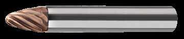
TOLERANCES (mm)
STEELS
STAINLESS STEELS
CAST IRON
• Designed to significantly improve traditional ball end applications
• Highly efficient at finishing and semifinishing profiling
• Main application areas include profiling and pocket milling
• Especially suited to machining deep pockets and hard-to-reach areas without using longreach tools
• Their versatility also allows for machining profiles and blends with one tool
• Recommended for materials ≤ 45 HRc (≤ 420 Bhn)
METRIC
Multi-Carb

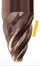
rpm= (Vc x 1000) / (DC x 3.14)
Feed= Fz x No. of teeth x rpm
Adjust speed and feed according to material hardness
Consider rpm according to cutting area of tool being utilized
Avoid using tip of the tool where possible due to reduced chip space
Be aware of max cut Ae, especially on the lower portion of the tool
Medical applications:
• Titanium can be cut dry while keeping cut size to a minimum and providing good chip evacuation (air blast)
• For cobalt chrome applications, a surface speed of 45M/min is a guide (It can also be cut dry as per colbalt) refer to the KYOCERA SGS APEX for complete technical information (www.kyocera-sgstool.com/apex)
TOLERANCES (inch)
1/8–1/4 DIAMETER
DC = +0.0000/–0.0012
DCON = h 6
RE = +0.0000/–0.0020
>1/4–3/8 DIAMETER
DC = +0.0000/–0.0016
DCON = h 6
RE = +0.0000/–0.0020
>3/8–1 DIAMETER
DC = +0.0000/–0.0020
DCON = h 6
RE = +0.0000/–0.0020

• Specially engineered step core design provides stability for aggressive ramping and rigidity when flutes are completely engaged
• Open design at axial end accommodates material flow and load reduction during machining operations
• Enhanced corner geometry with tight tolerance corner radii
• Recommended for materials ≤ 45 HRc (≤ 420 Bhn)
CARBON STEELS
1018, 1040, 1080, 1090, 10L50, 1140, 1212, 12L15, 1525, 1536
ALLOY STEELS
4140, 4150, 4320, 5120, 5150, 8630, 86L20, 50100
TOOL STEELS
A2, D2, H13, L2, M2, P20, S7, T15, W2
STAINLESS STEELS (FREE MACHINING)
303, 416, 420F, 430F, 440F
STAINLESS STEELS (DIFFICULT)
304, 304L, 316, 316L
275 Bhn or ≤ 28 HRc
STAINLESS STEELS (PH)
13-8 PH, 15-5 PH, 17-4 PH, Custom 450
35 HRc
continued on next page
IRONS (HIGH ALLOY)
HIGH TEMP ALLOYS (NICKEL,
Inconel 601, 617, 625, Incoloy, Monel 400
HIGH TEMP ALLOYS (NICKEL, COBALT, IRON BASE)
Inconel 718, X-750, Incoloy, Waspaloy, Hastelloy, Rene
TITANIUM ALLOYS
Pure Titanium, Ti6Al4V, Ti6Al2Sn4Zr2Mo, Ti4Al4Mo2Sn0.5Si
43
TITANIUM ALLOYS (DIFFICULT)
Ti10V2Fe3Al, Ti5Al5V5Mo3Cr, Ti7Al4Mo, Ti3Al8V6Cr4Zr4Mo, Ti6Al6V6Sn, Ti15V3 Cr3Sn3Al
Bhn (Brinell) HRc (Rockwell C)
rpm = Vc x 3.82 / DC
ipm = Fz x 3 x rpm reduce speed and feed for materials harder than listed reduce feed and Ae when finish milling (.02 x DC maximum) feed rates listed have chip thinning adjustments included where applicable refer to the KYOCERA SGS APEX for complete technical information (www.kyocera-sgstool.com/apex)
• Specially engineered step core design provides stability for aggressive ramping and rigidity when flutes are completely engaged
• Open design at axial end accommodates material flow and load reduction during machining operations
• Enhanced corner geometry with tight tolerance corner radii
• Recommended for materials ≤ 45 HRc (≤ 420 Bhn)
TOLERANCES (mm)
3–6 DIAMETER DC = +0,000/–0,030
= h 6
= +0,000/–0,050
>6–10 DIAMETER DC = +0,000/–0,040
= h 6 RE = +0,000/–0,050
>10–20 DIAMETER
DC = +0,000/–0,050
DCON = h 6
RE = +0,000/–0,050
CARBON STEELS
1018, 1040, 1080, 1090, 10L50, 1140, 1212, 12L15, 1525, 1536
ALLOY STEELS
4140, 4150, 4320, 5120, 5150, 8630, 86L20, 50100
275 Bhn or ≤ 28 HRc
TOOL STEELS
A2, D2, H13, L2, M2, P20, S7, T15, W2
375 Bhn or
40 HRc
STEELS (FREE MACHINING)
303, 416, 420F, 430F, 440F
STAINLESS STEELS (DIFFICULT)
304, 304L, 316, 316L
STEELS
continued on next page
K CAST IRONS (LOW & MEDIUM ALLOY) Gray, Malleable, Ductile
HIGH TEMP ALLOYS (NICKEL, COBALT, IRON BASE)
Inconel 601, 617, 625, Incoloy, Monel 400
HIGH TEMP ALLOYS
(NICKEL, COBALT, IRON BASE)
Inconel 718, X-750, Incoloy, Waspaloy, Hastelloy, Rene
43
TITANIUM ALLOYS
Pure Titanium, Ti6Al4V, Ti6Al2Sn4Zr2Mo, Ti4Al4Mo2Sn0.5Si ≤ 350 Bhn or ≤ 38 HRc
TITANIUM ALLOYS (DIFFICULT)
Ti10V2Fe3Al, Ti5Al5V5Mo3Cr, Ti7Al4Mo, Ti3Al8V6Cr4Zr4Mo, Ti6Al6V6Sn, Ti15V3 Cr3Sn3Al
≤
or ≤ 45 HRc
Bhn (Brinell) HRc (Rockwell C)
rpm = (Vc x 1000) / (DC x 3.14)
mm/min = Fz x 3 x rpm reduce speed and feed for materials harder than listed reduce feed and Ae when finish milling (.02 x DC maximum) feed rates listed have chip thinning adjustments included where applicable refer to the KYOCERA SGS APEX for complete technical information (www.kyocera-sgstool.com/apex)


• Variable pitch allows for improved chatter suppression along with improved surface finish and enhanced tool life
• Raised land and increased core diameter designed to enhance tool life and decrease tool deflection
• Recommended for materials ≤ 45 HRc (≤ 420 Bhn)

• Variable pitch allows for improved chatter suppression along with improved surface finish and enhanced tool life
• Raised land and increased core diameter designed to enhance tool life and decrease tool deflection
• Ball end design ideal for finishing operations in complex workpieces
• Recommended for materials ≤ 45 HRc (≤ 420 Bhn)
P CARBON STEELS
1018, 1040, 1080, 1090, 10L50, 1140, 1212, 12L15, 1525, 1536
ALLOY STEELS
4140, 4150, 4320, 5120, 5150, 8630, 86L20, 50100
TOOL STEELS
A2, D2, H13, L2, M2, P20, S7, T15, W2
M STAINLESS STEELS (FREE MACHINING) 303, 416, 420F, 430F, 440F
STEELS (DIFFICULT)
304L, 316, 316L
HIGH TEMP ALLOYS (NICKEL, COBALT, IRON BASE)
Inconel 601, 617, 625, Incoloy, Monel 400
HIGH TEMP ALLOYS (NICKEL, COBALT, IRON BASE)
Inconel 718, X-750, Incoloy, Waspaloy, Hastelloy, Rene
TITANIUM ALLOYS
Pure Titanium, Ti6Al4V, Ti6Al2Sn4Zr2Mo, Ti4Al4Mo2Sn0.5Si
TITANIUM ALLOYS (DIFFICULT)
Ti10V2Fe3Al, Ti5Al5V5Mo3Cr, Ti7Al4Mo, Ti3Al8V6Cr4Zr4Mo, Ti6Al6V6Sn, Ti15V3 Cr3Sn3Al
Bhn (Brinell) HRc (Rockwell C)
rpm = Vc x 3.82 / DC
ipm = Fz x 4 x rpm reduce speed and feed for materials harder than listed feed rates listed have chip thinning adjustments included where applicable refer to the KYOCERA SGS APEX for complete technical information (www.kyocera-sgstool.com/apex)
SERIES
• Variable pitch allows for improved chatter suppression along with improved surface finish and enhanced tool life
• Raised land and increased core diameter designed to enhance tool life and decrease tool deflection
• Recommended for materials ≤ 45 HRc (≤ 420 Bhn)
70559
70562
• Variable pitch allows for improved chatter suppression along with improved surface finish and enhanced tool life
• Raised land and increased core diameter designed to enhance tool life and decrease tool deflection
• Ball end design ideal for finishing operations in complex workpieces
• Recommended for materials ≤ 45 HRc (≤ 420 Bhn)
P CARBON STEELS
1018, 1040, 1080, 1090, 10L50, 1140, 1212, 12L15, 1525, 1536
ALLOY STEELS
4140, 4150, 4320, 5120, 5150, 8630, 86L20, 50100
TOOL STEELS
A2, D2, H13, L2, M2, P20, S7, T15, W2
M STAINLESS STEELS (FREE MACHINING) 303, 416, 420F, 430F, 440F
STAINLESS STEELS (DIFFICULT)
STAINLESS STEELS (PH)
13-8 PH, 15-5 PH, 17-4 PH, Custom 450
CAST IRONS (LOW & MEDIUM ALLOY) Gray, Malleable, Ductile
CAST IRONS (HIGH ALLOY) Gray, Malleable, Ductile
HIGH TEMP ALLOYS (NICKEL, COBALT, IRON BASE)
Inconel 601, 617, 625, Incoloy, Monel 400
HIGH TEMP ALLOYS (NICKEL, COBALT, IRON BASE)
Inconel 718, X-750, Incoloy, Waspaloy, Hastelloy, Rene
TITANIUM ALLOYS
Pure Titanium, Ti6Al4V, Ti6Al2Sn4Zr2Mo, Ti4Al4Mo2Sn0.5Si
TITANIUM ALLOYS (DIFFICULT)
Ti10V2Fe3Al, Ti5Al5V5Mo3Cr, Ti7Al4Mo, Ti3Al8V6Cr4Zr4Mo, Ti6Al6V6Sn, Ti15V3 Cr3Sn3Al
Bhn (Brinell) HRc (Rockwell C)
rpm = (Vc x 1000) / (DC x 3.14)
375 Bhn or
40 HRc
19 HRc
mm/min = Fz x 4 x rpm reduce speed and feed for materials harder than listed feed rates listed have chip thinning adjustments included where applicable refer to the KYOCERA SGS APEX for complete technical information (www.kyocera-sgstool.com/apex)
• Short flute length and rigid design to reduce deflection
• S-Gash Ball geometry minimizes load and heat produced during the cutting process, ultimately enhancing tool life
• Ideal for machining complex contoured shapes in hardened steels
• Recommended for materials 35 to 60 HRc (327 to 654 Bhn)

• Short flute length and rigid design to reduce deflection
• S-Gash Ball geometry minimizes load and heat produced during the cutting process, ultimately enhancing tool life
• Ideal for machining complex contoured shapes in hardened steels
• Recommended for materials 35 to 60 HRc (327 to 654 Bhn)
Extended Neck Option Available, contact your local KSPT representative for more information. RE = 1/2 Cutting Diameter (DC)
TOLERANCES (inch)
1/32–3/32 DIAMETER
DC = +0.0000/–0.0010
DCON = h 6
>3/32–1/4 DIAMETER
DCON = h 6 RE = +0.0000/–0.0006
>1/4–3/8 DIAMETER
DC = +0.0000/–0.0016
DCON = h 6
RE = +0.0000/–0.0008
>3/8–3/4 DIAMETER
DC = +0.0000/–0.0020
DCON = h 6
RE = +0.0000/–0.0010
Extended Neck Option Available, contact your local KSPT representative for
TOLERANCES (mm)
1–2,5 DIAMETER
DC = +0,000/–0,025
DCON = h 6
RE = +0,000/–0,0013
>2,5–6 DIAMETER
DC = +0,000/–0,030
DCON = h 6
RE = +0,000/–0,0013
>6–10 DIAMETER
DC = +0,000/–0,040
DCON = h 6
RE = +0,000/–0,0020
>10–20 DIAMETER
DC = +0,000/–0,050
DCON = h 6
RE = +0,000/–0,0025
P
TOOL STEELS MOLD AND DIE STEEL
300M, 4340, 52100, HP-9-4-20, M50, A2, D2, H13, L2, M2, P20, S7, T15, W2
H TOOL STEELS
MOLD AND DIE STEEL
300M, 4340, 52100,
HP-9-4-20, M50, A2, D2, H13, L2, M2, P20, S7, T15, W2
TOOL STEELS
MOLD AND DIE STEEL
300M, 4340, 52100, HP-9-4-20, M50, A2, D2, H13, L2, M2, P20, S7, T15, W2
Bhn (Brinell) HRc (Rockwell C) HSM (High Speed Machining)
rpm = Vc x 3.82 / DC
ipm = Fz x 2 x rpm
reduce speed and feed for materials harder than listed reduce feed and Ae when finish milling (.02 x DC maximum) feed rates listed have chip thinning adjustments included where applicable refer to the KYOCERA SGS APEX for complete technical information (www.kyocera-sgstool.com/apex)
TOOL STEELS MOLD AND DIE STEEL
300M, 4340, 52100, HP-9-4-20, M50, A2, D2, H13, L2, M2, P20, S7, T15, W2
H TOOL STEELS
MOLD AND DIE STEEL
300M, 4340, 52100, HP-9-4-20, M50, A2, D2, H13, L2, M2, P20, S7, T15, W2
TOOL STEELS
MOLD AND DIE STEEL
300M, 4340, 52100, HP-9-4-20, M50, A2, D2, H13, L2, M2, P20, S7, T15, W2
Bhn (Brinell) HRc (Rockwell C) HSM (High Speed Machining) rpm = (Vc x 1000) / (DC x 3.14) mm/min = Fz x 2 x rpm reduce speed and feed for materials harder than listed reduce feed and Ae when finish milling (.02 x DC maximum) feed rates listed have chip thinning adjustments included where applicable refer to the KYOCERA SGS APEX for complete technical information (www.kyocera-sgstool.com/apex)
Power-Carb
• Ideal in Trochoidal milling applications in hardened steels and dry machining
• Short flute length and large core design to reduce deflection
• Unsurpassed edge strength with extreme negative rake and eccentric relief
• Recommended for materials 45 to 65 HRc (421 to 739 Bhn)
57M METRIC SERIES
• Ideal in Trochoidal milling applications in hardened steels and dry machining
• Short flute length and large core design to reduce deflection
• Unsurpassed edge strength with extreme negative rake and eccentric relief
• Recommended for materials 45 to 65 HRc (421 to 739 Bhn)
Neck Option Available
Neck Option Available
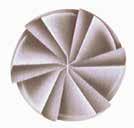
TOLERANCES (inch)
1/4 DIAMETER DC = +0.0000/–0.0012
= h 6
5/16 DIAMETER
3/8 DIAMETER
1/2 DIAMETER
= h 6
TOLERANCES (mm)
6 DIAMETER
DC = +0,000/–0,030 DCON = h 6
8 DIAMETER
DC = +0,000/–0,040 DCON = h 6
10 DIAMETER
DC = +0,000/–0,040 DCON = h 6
12–20 DIAMETER
DC = +0,000/–0,050 DCON = h 6
TOOL STEELS
MOLD AND DIE STEEL
300M, 4340, 52100, HP-9-4-20, M50, A2, D2, H13, L2, M2, P20, S7, T15, W2
300M, 4340, 52100, HP-9-4-20, M50, A2, D2, H13, L2, M2, P20, S7, T15, W2
Bhn (Brinell) HRc (Rockwell C) HSM (High Speed Machining) rpm = Vc x 3.82 / DC
ipm = Fz x 6 x rpm
reduce speed and feed for materials harder than listed reduce feed and Ae when finish milling (.02 x DC maximum) feed rates listed have chip thinning adjustments included where applicable refer to the KYOCERA SGS APEX for complete technical information (www.kyocera-sgstool.com/apex)
Power-Carb
P
TOOL STEELS
MOLD AND DIE STEEL
300M, 4340, 52100, HP-9-4-20, M50, A2, D2, H13, L2, M2, P20, S7, T15, W2
TOOL STEELS
MOLD AND DIE STEEL
300M, 4340, 52100, HP-9-4-20,
TOOL STEELS
MOLD AND DIE STEEL
300M, 4340, 52100, HP-9-4-20, M50, A2, D2, H13, L2, M2, P20, S7, T15, W2
740 Bhn or ≤ 65 HRc
Bhn (Brinell) HRc (Rockwell C) HSM (High Speed Machining) rpm = (Vc x 1000) / (DC x 3.14) mm/min = Fz x 6 x rpm reduce speed and feed for materials harder than listed reduce feed and Ae when finish milling (.02 x DC maximum) feed rates listed have chip thinning adjustments included where applicable refer to the KYOCERA SGS APEX for complete technical information (www.kyocera-sgstool.com/apex)
TOLERANCES (inch)
DC = +0.0000/–0.0030
DCON = h 6
• Slow helix design adds strength to the edge allowing ease for milling highly abrasive materials
• Two levels of chatter suppression: variable helix and indexing
• Excels at roughing (slotting, profiling) and finishing in a variety of plastics and composites
TOLERANCES (mm)
DC = +0,000/–0,080
DCON = h 6
• Slow helix design adds strength to the edge allowing ease for milling highly abrasive materials
• Two levels of chatter suppression: variable helix and indexing
• Excels at roughing (slotting, profiling) and finishing in a variety of plastics and composites
GRAPHITE
HSM (High Speed Machining)
rates shown are for use without coolant; rates may be increased with coolant rpm = Vc x 3.82 / DC dust collection is vital when machining dry ipm = Fz x 4 x rpm diamond coating will increase tool life in graphite and composite materials adjust parameters based on resin type and fiber structure feed rates listed have chip thinning adjustments included where applicable reduce speed when overheating causes melting or damage to resin refer to the KYOCERA SGS APEX for complete technical information reduce feed if delamination or fraying occur (www.kyocera-sgstool.com/apex) finish cuts typically required reduced feed and cutting depths
HSM (High Speed Machining)
rates shown are for use without coolant; rates may be increased with coolant rpm = Vc x 3.82 / DC dust collection is vital when machining dry mm/min = Fz x 4 x rpm diamond coating will increase tool life in graphite and composite materials adjust parameters based on resin type and fiber structure feed rates listed have chip thinning adjustments included where applicable reduce speed when overheating causes melting or damage to resin refer to the KYOCERA SGS APEX for complete technical information reduce feed if delamination or fraying occur (www.kyocera-sgstool.com/apex) finish cuts typically required reduced feed and cutting depths
Picatinny Rail Tools

Ferrous Recoil Groove Tool
• Open Flute design improves chip removal at high feed rates
• Specially engineered flute shape for improved chip control
• Circular land improves surface finish and chatter supression
• Symmetrical end gashing improves balance in high speed operations
• Meets US MIL-STD 1913 & NATO STANAG 4694
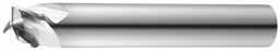
Non-Ferrous Recoil Groove Tool
FRACTIONAL SERIES
• Open Flute design improves chip removal at high feed rates
• Circular land improves surface finish and chatter supression
• Symmetrical end gashing improves balance in high speed operations
• 45 degree chamfer enables slot and deburr in one operation
• Meets US MIL-STD 1913 & NATO STANAG 4694

(inch)
P
Picatinny Rail Recoil Groove Tool 3 Flute Made to MIL-STD-1913
CARBON STEELS
1018, 1040, 1080, 1090, 10L50, 1140, 1212, 12L15, 1525, 1536
ALLOY STEELS
4140, 4150, 4320, 5120, 5150, 8630, 86L20, 50100
TOOL STEELS
A2, D2, H13, L2, M2, P20, S7, T15, W2
STEELS (FREE MACHINING)
416, 420F, 430F, 440F
Picatinny Rail Ferrous Recoil Groove Tool
ALLOYS (NICKEL, COBALT, IRON BASE)
Inconel 601, 617, 625, Incoloy, Monel 400
Inconel 718, X-750, Incoloy, Waspaloy, Hastelloy, Rene
TITANIUM ALLOYS
Pure Titanium, Ti6Al4V, Ti6Al2Sn4Zr2Mo, Ti4Al4Mo2Sn0.5Si
TITANIUM ALLOYS (DIFFICULT)
Ti10V2Fe3Al, Ti5Al5V5Mo3Cr, Ti7Al4Mo, Ti3Al8V6Cr4Zr4Mo, Ti6Al6V6Sn, Ti15V3 Cr3Sn3Al
Bhn (Brinell) HRc (Rockwell C) when recommended speed exceeds your capability, use maximum available and recalculate ipm rpm = Vc x 3.82 / DC ipm = Fz x 3 x rpm reduce speed and feed for materials harder than listed reduce feed and Ae when finish milling (.02 x DC maximum) refer to the KYOCERA SGS APEX for complete technical information (www.kyocera-sgstool.com/apex)
Picatinny Rail Non-Ferrous Recoil Groove Tool
Picatinny Rail Non-Ferrous Recoil
Groove Tool 3 Flute Made to MIL-STD-1913 Hardness
ALLOYS
ALUMINUM DIE CAST ALLOYS (HIGH SILICONE)
A-392, B-390
Bhn (Brinell) HRc (Rockwell C) HRb (Rockwell B) when recommended speed exceeds your capability, use maximum available and recalculate ipm rpm = Vc x 3.82 / DC ipm = Fz x 3 x rpm reduce speed and feed for materials harder than listed reduce feed and Ae when finish milling (.02 x DC maximum) refer to the KYOCERA SGS APEX for complete technical information (www.kyocera-sgstool.com/apex)
TOLERANCES (inch)
DC = +0.0010/–0.0010
STAINLESS STEELS
CAST IRON
HIGH TEMP ALLOYS
NON-FERROUS

Ferrous Dovetail Form Tool
• Five-flute design allows for higher machining parameters
• Open end work design allows for increased chip space
• Square end configuration with enhanced corner strength to improve corner durability
• Meets US MIL-STD 1913 & NATO STANAG 4694

Non-Ferrous Dovetail Form Tool
• Open Flute design improves chip removal at high feed rates
• Specially engineered flute shape for improved chip control
• Circular land improves surface finish and chatter supression
• Symmetrical end gashing improves balance in high speed operations
• Meets US MIL-STD 1913 & NATO STANAG 4694
Picatinny Rail Ferrous Dovetail Form Tool
Picatinny Rail
Dovetail Form Tool 5 Flute Made to MIL-STD-1913 Hardness
CARBON STEELS
1018, 1040, 1080, 1090, 10L50, 1140, 1212, 12L15, 1525, 1536
ALLOY STEELS
P
4140, 4150, 4320, 5120, 5150, 8630, 86L20, 50100
TOOL STEELS
A2, D2, H13, L2, M2, P20, S7, T15, W2
STAINLESS STEELS (FREE MACHINING)
303, 416, 420F, 430F, 440F
M
STAINLESS STEELS (DIFFICULT) 304, 304L, 316, 316L
STAINLESS STEELS (PH)
13-8 PH, 15-5 PH, 17-4 PH, Custom 450
K CAST IRONS (LOW & MEDIUM ALLOY) Gray, Malleable, Ductile
HIGH TEMP ALLOYS (NICKEL, COBALT, IRON BASE)
Inconel 601, 617, 625, Incoloy, Monel 400
HIGH TEMP ALLOYS (NICKEL, COBALT, IRON BASE)
Inconel 718, X-750, Incoloy, Waspaloy, Hastelloy, Rene
TITANIUM ALLOYS
Pure Titanium, Ti6Al4V, Ti6Al2Sn4Zr2Mo, Ti4Al4Mo2Sn0.5Si
TITANIUM ALLOYS (DIFFICULT)
Ti10V2Fe3Al, Ti5Al5V5Mo3Cr, Ti7Al4Mo, Ti3Al8V6Cr4Zr4Mo, Ti6Al6V6Sn, Ti15V3 Cr3Sn3Al
Bhn (Brinell) HRc (Rockwell C) when recommended speed exceeds your capability, use maximum available and recalculate ipm rpm = Vc x 3.82 / DC ipm = Fz x 5 x rpm reduce speed and feed for materials harder than listed reduce feed and Ae when finish milling (.02 x DC maximum) refer to the KYOCERA SGS APEX for complete technical information (www.kyocera-sgstool.com/apex)
Picatinny Rail Non-Ferrous Dovetail Form Tool
Bhn (Brinell) HRc (Rockwell C) HRb (Rockwell B) when recommended speed exceeds your capability, use maximum available and recalculate ipm rpm = Vc x 3.82 / DC ipm = Fz x 3 x rpm reduce speed and feed for materials harder than listed reduce feed and Ae when finish milling (.02 x DC maximum) refer to the KYOCERA SGS APEX for complete technical information (www.kyocera-sgstool.com/apex)
Solid Car bide Tools
VALUE AT THE SPINDLE
High Performance Aluminum End Mills
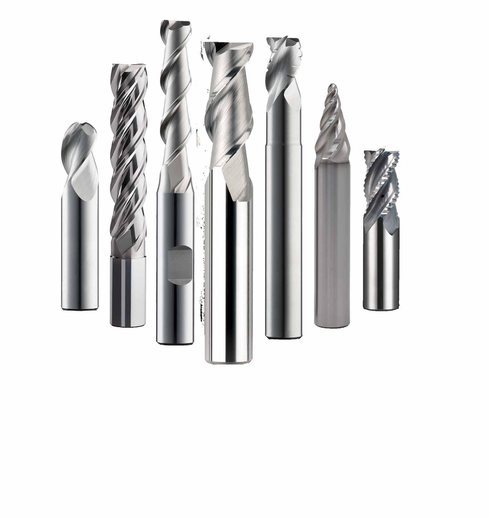
FRESAS DE ALTO RENDIMIENTO PARA ALUMINIO
S-Carb APR y APF
43APR-3 3 filos, productividad avanzada, desbastador, fraccional
43APR-3 3 filos, productividad avanzada, desbastador, métrico
43APR-4 4 filos, productividad avanzada, desbastador, métrico
43APF 4 filos, productividad avanzada, acabador, fraccional
43MAPF 4 filos, productividad avanzada, acabador, métrico
S-Carb APF-B 43APF-B Fresas de forma cónica de segmento circular de múltiples filos, métrico
S-Carb (3 filos)
Desbastador S-Carb (3 filos)
S-Carb (2 filos)
Ski-Carb
43 3 filos, no férrico, punta cuadrada, fraccional
43CR 3 filos, no férrico, radio angulado, fraccional
43L 3 filos, no férrico, punta cuadrada, largo alcance, fraccional
43LC 3 filos, no férricos, largo alcance, radio angulado, fraccional
43EC 3 filos, no férrico, punta cuadrada, alcance extralargo,
43B 3 filos, no férrico, punta esférica, fraccional
43LB 3 filos, no férrico, punta esférica, largo alcance, fraccional
43EB 3 filos, no férrico, punta esférica, alcance
43M 3 filos, no férrico, punta cuadrada,
43MCR 3
43ML 3 filos, no férrico, punta cuadrada,
43MLC 3
43MB 3
43MLB 3 filos, no férrico, punta esférica, largo alcance, métrico
43CB 3 filos, desbastador, no férrico, rompevirutas, fraccional
43LCB 3 filos, desbastador, no férrico, rompevirutas, largo alcance, fraccional
43MCB 3 filos, desbastador, no férrico, rompevirutas, métrico
47 2 filos, no férrico, punta cuadrada, fraccional
47L 2 filos, no férrico, punta cuadrada, largo alcance, fraccional
47B 2 filos, no férrico, punta esférica, fraccional
47LB 2 filos, no férrico, punta esférica, largo alcance, fraccional
47M 2 filos, no férrico, punta cuadrada, métrico
47ML 2 filos, no férrico, punta cuadrada, largo alcance, métrico
47MB 2 filos, no férrico, punta esférica, métrico
47MLB 2 filos, no férrico, punta esférica, largo alcance, métrico
44 2 filos, materiales no férricos, punta cuadrada, fraccional
44M 2 filos, materiales no férricos, punta cuadrada, métrico
45 2 filos, materiales no férricos, largo alcance, radio angulado, fraccional
Recomendaciones de velocidades y avances mostradas tras cada serie
Recommandations de vitesse et avance indiquées après chaque série
Fräsen
Schruppfräser (3 Schneiden)
(2 Schneiden)
Empfehlungen für Drehzahl & Vorschub im Anhang zu jeder Serie


DC = –0.0004/–0.004
DCON = h 6
RE = +/–0.002
• Ultra high-productivity rougher for Aluminum alloys, specifically for aircraft components
• Designed for high material removal rates (MRR)
• New 3 flute variable geometry with side exit coolant holes
• Open fluting for deep slotting and profiling
• Recommended for materials ≤ 150 Bhn (≤ 7 HRc)
S-Carb APR
RPM stated may be outside of most machine tools in the smaller sizes, adjust the surface speed but maintain the Fz For best results use the peak power of the specific machine torque chart. Typically 10hp is required to remove 45 cubic inches of material (MRR).
Eg. >> (Ae x Ap x Feed) >> Therefore Full slotting 1" dia: 1 x 1 x 355 = 355 cubic inches, so it needs a min of 78hp.
Larger cuts and chip load consume more power.
Review the power chart of each machine to determine MAX power for ultimate performance. Example below shows peak power @ 10,000 rpm. The new coolant supply is designed for MQL as well as normal emulsion coolant on the same data. Ensure max MQL flow prior to cutting. refer to the KYOCERA SGS APEX for complete technical information (www.kyocera-sgstool.com/apex)
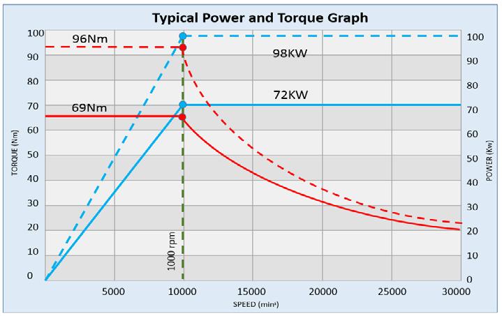
TOLERANCES (mm)
12–25 DIAMETER
DC = –0,010/–0,100
DCON = h 6
RE = +/–0,05
*Variable Helix
• Ultra high-productivity rougher for Aluminum alloys, specifically for aircraft components
• Designed for high material removal rates (MRR)
• New 3 flute variable geometry with side exit coolant holes
• Open fluting for deep slotting and profiling
• Recommended for materials ≤ 150 Bhn (≤ 7 HRc)


43APR-4 METRIC SERIES
• Ultra high-productivity rougher for Aluminum alloys, specifically for aircraft components
• Designed for high material removal rates (MRR)
• 4 flute variable geometry with side exit coolant holes
• Open fluting for deep slotting and profiling
• Recommended for materials ≤ 150 Bhn (≤ 7 HRc)

TOLERANCES (mm)
20–25 DIAMETER
= –0,010/–0,100
= h 6
= ±0,050
RPM stated may be outside of most machine tools in the smaller sizes, adjust the surface speed but maintain the Fz
For best results use the peak power of the specific machine torque chart.
Typically 10kw is required to remove 1 litre of material (MMR).
Eg. >> (Ae x Ap x Feed) / 1000000 >> Therefore Full slotting Ø25: 25 x 25 x 7333 = 4.58 Litres so it needs a min of 46Kw.
Larger cuts and chip load consume more power.
Review the power chart of each machine to determine MAX power for ultimate performance.
Example below shows peak power @ 10,000 rpm.
The APR-4 design is for ultimate metal removal but typicaly requires more power, and is also better suited to horizontal machines.
The new coolant supply is designed for MQL as well as normal emulsion coolant on the same data.
Ensure max MQL flow prior to cutting. refer to the KYOCERA SGS APEX for complete technical information (www.kyocera-sgstool.com/apex)
S-Carb APF


• Ultra high-productivity finisher for Aluminum alloys, specifically for aircraft components
• Two levels of chatter suppression: variable helix and indexing
• Designed for single axial pass semi-finishing and finishing
• Polished flutes maximize chip evacuation and provides enhanced finish
• Recommended for materials ≤ 150 Bhn (≤ 7 HRc)
Available on request: • JetStream Technology
2024, 5052, 5086, 6061, 6063, 7075
N ALUMINUM ALLOYS
ALUMINUM ALLOYS (LITHIUM)*
2090, 2091, 2099, 2195, 2199, 2297, 8090
150 Bhn or
88 HRb
150 Bhn or
88 HRb
Bhn (Brinell) HRb (Rockwell B) surface speed is dependent on machine spindle and fixturing balancing is recommended at ultra high surface speeds tool life may be reduced when machining Lithium Alloys rpm = Vc x 3.82 / DC ipm = Fz x 4 x rpm maximum recommended depths shown reduce speed and feed for materials harder than listed finish cuts typically require reduced feed and cutting depths of 0.02 X DC maximum ramp angle = 6˚ (feed rate = 50%) plunging not recommended refer to the KYOCERA SGS APEX for complete technical information (www.kyocera-sgstool.com/apex)
S-Carb APF
• Ultra high-productivity finisher for Aluminum alloys, specifically for aircraft components
• Two levels of chatter suppression: variable helix and indexing
• Designed for single axial pass semi-finishing and finishing
• Polished flutes maximize chip evacuation and provides enhanced finish
• Recommended for materials ≤ 150 Bhn (≤ 7 HRc)
Available on request: • JetStream Technology
TOLERANCES (mm)
6–25 DIAMETER
= –0,010/–0,050
= h 6
= +0,03/–0,03
2024, 5052, 5086, 6061, 6063, 7075
N ALUMINUM ALLOYS
ALUMINUM ALLOYS (LITHIUM)*
2090, 2091, 2099, 2195, 2199, 2297, 8090
150 Bhn or
88 HRb
150 Bhn or
88 HRb
Bhn (Brinell) HRb (Rockwell B) surface speed is dependent on machine spindle and fixturing balancing is recommended at ultra high surface speeds *tool life may be reduced when machining Lithium Alloys rpm = (Vc x 1000) / (DC x 3.14) mm/min = Fz x 4 x rpm maximum recommended depths shown reduce speed and feed for materials harder than listed finish cuts typically require reduced feed and cutting depths of 0.02 X DC maximum ramp angle = 6˚ (feed rate = 50%) plunging not recommended refer to the KYOCERA SGS APEX for complete technical information (www.kyocera-sgstool.com/apex)
S-Carb APF-B


43APF-B

SERIES
• Designed to significantly improve traditional ball end applications
• Highly efficient at finishing and semifinishing profiling
• Main application areas include profiling and pocket milling
• Especially suited to machining deep pockets and hard-to-reach areas without using long-reach tools
• Their versatility also allows for machining profiles and blends with one tool
• Recommended for materials ≤ 150 Bhn (≤ 7 HRc)
Nrpm = (Vc x 1000) / (DC x 3.14)
Feed= Fz x No. of flutes x rpm
Adjust speed and feed cutting
Adjust rates according to cutting area of tool being used

Avoid using tip of the tool where possible due to reduced chip space
Be aware of max cut Ae, especially on the lower portion of the tool refer to the KYOCERA SGS APEX for complete technical information (www.kyocera-sgstool.com/apex)
S-Carb

• Circular land allows for increased control at various speed and feed rates and reduces chatter
• Symmetrical end gashing for excellent balance at high speeds and aggressive plunging capability
• Open fluting for deep slotting and profiling
• Enhanced corner geometry with tight tolerance corner radii
• Recommended for materials ≤ 150 Bhn (≤ 7 HRc)
1/2 2-1/2 1/4
34824 34859 1/4 3/4 2-1/2 1/4 – 34704 34731
1/4 3/4 2-1/2 1/4 .010 34773 34795
1/4 3/4 2-1/2 1/4 .015 35579 35669
1/4 3/4 2-1/2 1/4 .030 34774 34796
1/4 3/4 2-1/2 1/4 .060 35580 35670
1/4 1 3 1/4 – 34825 34860
1/4 1 3 1/4 .010 35581 35671
1/4 1 3 1/4 .015 35582 35672
1/4 1 3 1/4 .030 35583 35673 1/4 1 3 1/4 .060 35584 35674
1/4
on next page
TOLERANCES (inch)
1/8–3/16 DIAMETER
1/4–3/8 DIAMETER
1/2–5/8 DIAMETER
= h 6
3/4–1 DIAMETER DC = +0.0000/–0.00051 DCON = h 6
= +0.0000/–0.0020
TOLERANCES (inch)
1/8–3/16 DIAMETER
DC = +0.0000/–0.00032
DCON = h 6
RE = +0.0000/–0.0020
1/4–3/8 DIAMETER
DC = +0.0000/–0.00035
DCON = h 6
RE = +0.0000/–0.0020
1/2–5/8 DIAMETER
DC = +0.0000/–0.00043
DCON = h 6
RE = +0.0000/–0.0020
3/4–1 DIAMETER
DC = +0.0000/–0.00051
DCON = h 6
RE = +0.0000/–0.0020
NON-FERROUS
3/8 1 2-1/2 3/8
3/8 1 3 3/8
3/8 1-1/2 4 3/8
3/8 1-1/2 4 3/8 .015
3/8 1-1/2 4 3/8
3/8 1-1/2 4 3/8
1/2 5/8 2-1/2 1/2 – 34712 34739 1/2 5/8 3 1/2 .010 35597 35687 1/2 5/8 3 1/2 .015 35598 35688
1/2 5/8 3 1/2 .030 35599 35689
5/8 3 1/2 .120 35602 35692
1/2 1 3 1/2 – 34830 34865
TOLERANCES (inch)
1/8–3/16 DIAMETER
DC = +0.0000/–0.00032
DCON = h 6 RE = +0.0000/–0.0020
1/4–3/8 DIAMETER
DC = +0.0000/–0.00035
DCON = h 6 RE = +0.0000/–0.0020
1/2–5/8 DIAMETER DC = +0.0000/–0.00043 DCON = h 6 RE = +0.0000/–0.0020
3/4–1 DIAMETER
DC = +0.0000/–0.00051
DCON = h 6
RE = +0.0000/–0.0020
34743
5/8 3/4 3-1/2 5/8 .030 35622 35712
5/8 3/4 3-1/2 5/8 .060 35623 35713
5/8 3/4 3-1/2 5/8 .090 35624 35714
5/8 3/4 3-1/2 5/8 .120 35625 35715
5/8 1-5/8 3-3/4 5/8 – 34717 34744
5/8 1-5/8 3-3/4 5/8 .030 34782 34804
5/8 1-5/8 3-3/4 5/8 .060 34783 34805
5/8 1-5/8 3-3/4 5/8 .090 34784 34806
5/8 1-5/8 3-3/4 5/8 .120 35626 35716
5/8 2-1/8 4 5/8 – 34833 34868
5/8 2-1/2 5 5/8 – 34718 34745
5/8 3-1/4 6 5/8 – 34834 34869
5/8 3-3/4 6 5/8 – 34719 34746
3/4
3/4
34747
3/4 1 4 3/4 .060 35628 35718
3/4 1 4 3/4 .090
3/4
3/4
3/4
3/4 1-5/8
TOLERANCES (inch)
1/8–3/16 DIAMETER
DC = +0.0000/–0.00032
DCON = h 6
RE = +0.0000/–0.0020
1/4–3/8 DIAMETER
DC = +0.0000/–0.00035
DCON =
1/2–5/8 DIAMETER
DC = +0.0000/–0.00043
DCON = h 6
RE = +0.0000/–0.0020
3/4–1 DIAMETER
DC = +0.0000/–0.00051
DCON = h 6
RE = +0.0000/–0.0020
NON-FERROUS
3/4 2-1/4

• Circular land allows for increased control at various speed and feed rates and reduces chatter
• Symmetrical end gashing for excellent balance at high speeds and aggressive plunging capability
• Open fluting for deep slotting and profiling
• Necked design with blended diameter transitions provide clearance to reach
• Enhanced corner geometry with tight tolerance corner radii
• Recommended for materials ≤ 150 Bhn (≤ 7 HRc)
1/4
1/4 3/8 4 1/4 1-1/2 .230
1/4 3/8 4 1/4 1-1/2 .230 .010 32755 32819
1/4 3/8 4 1/4 1-1/2 .230 .030 32756 32820
1/4 3/8 4 1/4 2-1/8 .230 – 32704 32729
1/4 3/8 4 1/4 2-1/8 .230 .010 32757 32821
1/4 3/8 4 1/4 2-1/8 .230 .030 32758 32822
5/16 7/16 4 5/16 1-1/8 .292 – 32705 32730
5/16 7/16 4 5/16 1-1/8 .292 .030 32759 32823
5/16 7/16 4 5/16 2-1/8 .292 – 32706 32731
5/16 7/16 4 5/16 2-1/8 .292 .030 32760 32824
3/8 1/2 3 3/8 1-1/8 .355 .015 35791 36239
3/8 1/2 3 3/8 1-1/8 .355 .090 35792 36240
3/8 1/2 4 3/8 1-1/8 .355 – 32707 32732
3/8 1/2 4 3/8 1-1/8 .355 .030 32762 32826
3/8 1/2 4 3/8 1-1/8
3/8
3/8
3/8 1/2 4
32763 32827
TOLERANCES (inch)
1/8–3/16 DIAMETER DC = +0.0000/–0.00032
1/4–3/8 DIAMETER
= h 6
= +0.0000/–0.0020
1/2–5/8 DIAMETER DC = +0.0000/–0.00043
DCON = h 6 RE = +0.0000/–0.0020
3/4–1 DIAMETER
DC = +0.0000/–0.00051
DCON = h 6 RE = +0.0000/–0.0020
on next page
TOLERANCES (inch)
1/8–3/16 DIAMETER
DC = +0.0000/–0.00032
DCON = h 6
RE = +0.0000/–0.0020
1/4–3/8 DIAMETER
DC = +0.0000/–0.00035
DCON = h 6
RE = +0.0000/–0.0020
1/2–5/8 DIAMETER
DC = +0.0000/–0.00043
DCON = h 6
RE = +0.0000/–0.0020
3/4–1 DIAMETER
DC = +0.0000/–0.00051
DCON = h 6
RE = +0.0000/–0.0020
NON-FERROUS
5/8 3/4 4 5/8 1-3/4 .605 .030 32779 32843
5/8 3/4 4 5/8 1-3/4 .605 .060 32780 32844
5/8 3/4 4 5/8 1-3/4 .605 .090 32781 32845
5/8 3/4 4 5/8 1-3/4 .605 .120 32782 32846
5/8 3/4 4 5/8 2-3/8 .605 – 32713 32738
5/8 3/4 4 5/8 2-3/8 .605 .030 32783 32847
5/8 3/4 4 5/8 2-3/8 .605 .060 32784 32848
5/8 3/4 4 5/8 2-3/8 .605 .090 32785 32849
5/8 3/4 4 5/8 2-3/8 .605 .120 32786 32850
5/8 3/4 6 5/8 3-3/8 .605 – 32714 32739
5/8 3/4 6 5/8 3-3/8 .605 .030 32787 32851
5/8 3/4 6 5/8 3-3/8 .605 .060 32788 32852
5/8 3/4 6 5/8 3-3/8 .605 .090 32789 32853
5/8 3/4 6 5/8
3/4
3/4 1
3/4 1
3/4
3/4 1 6 3/4 3-3/8 .730 .030 32799 32863
3/4 1 6 3/4 3-3/8 .730 .060 32800 32864
3/4 1 6 3/4 3-3/8 .730 .090 32801 32865
3/4
3/4 1 6 3/4 4-3/8 .730 – 32699 34896 1 1-1/4 5 1 2-5/8 .980 .190 35809 36257
1 1-1/4 5 1 2-5/8 .980 .250 35810 36258
1 1-1/4 6 1 2-3/8 .980 – 32718 32743 1 1-1/4 6 1 2-3/8 .980 .030 32803 32867
1 1-1/4 6 1 2-3/8 .980 .060 32804 32868
1 1-1/4 6 1 2-3/8 .980 .090 32805 32869
1 1-1/4 6 1 2-3/8 .980 .120 32806 32870
1 1-1/4 6 1 3-3/8 .980 – 32719 32744 1 1-1/4 6 1 3-3/8 .980 .030 32807 32871 1 1-1/4 6 1 3-3/8 .980 .060 32808 32872 1 1-1/4
1/8–3/16 DIAMETER
1/4–3/8 DIAMETER
1/2–5/8 DIAMETER
= +0.0000/–0.00043
= h 6
3/4–1 DIAMETER
= +0.0000/–0.00051
= h 6
= +0.0000/–0.0020
TOLERANCES (inch)
1/4–3/8 DIAMETER
DC = +0.0000/–0.00035
DCON = h 6
RE = +0.0000/–0.0020
1/2–5/8 DIAMETER
DC = +0.0000/–0.00043
DCON = h 6
RE = +0.0000/–0.0020
3/4–1 DIAMETER
DC = +0.0000/–0.00051
DCON = h 6
RE = +0.0000/–0.0020
NON-FERROUS
• Circular land allows for increased control at various speed and feed rates and reduces chatter
• Symmetrical end gashing for excellent balance at high speeds and aggressive plunging capability
• Open fluting for deep slotting and profiling
• Necked design with blended diameter transitions provide clearance to reach
• Enhanced corner geometry with tight tolerance corner radii
• Recommended for materials ≤ 150 Bhn (≤ 7 HRc)
S-Carb
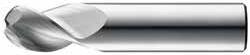
• Circular land allows for increased control at various speed and feed rates and reduces chatter
• Open fluting for deep slotting and profiling
• Ball end design ideal for finishing operations in complex workpieces
• Recommended for materials ≤ 150 Bhn (≤ 7 HRc)
RE = 1/2 Cutting Diameter (DC)
TOLERANCES (inch)
1/4–3/8 DIAMETER
1/2–5/8 DIAMETER
= +0.0000/–0.00043
= h 6
= +0.0005/–0.0005
3/4–1 DIAMETER
= h 6

TOLERANCES (inch)
1/4–3/8 DIAMETER
DC = +0.0000/–0.00035
DCON = h 6
RE = +0.0005/–0.0005
1/2–5/8 DIAMETER
DC = +0.0000/–0.00043
DCON = h 6
RE = +0.0005/–0.0005
3/4–1 DIAMETER
DC = +0.0000/–0.00051
DCON = h 6
RE = +0.0005/–0.0005
•
•
•
•
• Recommended for materials ≤ 150 Bhn (≤ 7 HRc)
TOLERANCES (inch)
1/4–3/8 DIAMETER
DC = +0.0000/–0.00035
DCON = h 6
RE = +0.0005/–0.0005
1/2–5/8 DIAMETER
DC = +0.0000/–0.00043
DCON = h 6
RE = +0.0005/–0.0005
3/4–1 DIAMETER
DC = +0.0000/–0.00051
DCON = h 6
RE = +0.0005/–0.0005
NON-FERROUS
• Circular land allows for increased control at various speed and feed rates and reduces chatter
• Open fluting for deep slotting and profiling
• Necked design with blended diameter transitions provide clearance to reach
• Ball end design ideal for finishing operations in complex workpieces
• Recommended for materials ≤ 150 Bhn (≤ 7 HRc)
S-Carb
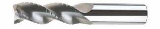
• Circular land allows for increased control at various speed and feed rates and reduces chatter
• Symmetrical end gashing for excellent balance at high speeds and aggressive plunging capability
• Chip breakers reduce machine loads up to 15% for increased roughing feed rate capability
• Open fluting for deep slotting and profiling
• Recommended for materials ≤ 150 Bhn (≤ 7 HRc)
TOLERANCES (inch)
1/4–3/8 DIAMETER
1/2–5/8 DIAMETER
= h 6
3/4–1 DIAMETER
= +0.0000/–0.00051 DCON = h 6
= +0.0000/–0.0020
3/8 2 4 3/8 .020 33404 33464 1/2 5/8 3 1/2 .030 33406 33466 1/2 1 3 1/2 .030 33407 33467 1/2 1-1/4 3-1/4 1/2 .030 34301 34306
1-5/8

TOLERANCES (inch)
1/4–3/8 DIAMETER
DC = +0.0000/–0.00035
DCON = h 6
RE = +0.0000/–0.0020
1/2–5/8 DIAMETER
DC = +0.0000/–0.00043
DCON = h 6
RE = +0.0000/–0.0020
3/4–1 DIAMETER
DC = +0.0000/–0.00051
DCON = h 6
RE = +0.0000/–0.0020
• Circular land allows for increased control at various speed and feed rates and reduces chatter
• Symmetrical end gashing for excellent balance at high speeds and aggressive plunging capability
• Chip breakers reduce machine loads up to 15% for increased roughing feed rate capability
• Open fluting for deep slotting and profiling
• Necked design with blended diameter transitions provide clearance to reach
• Recommended for materials ≤ 150 Bhn (≤ 7 HRc)
S-Carb
Series 43CR, 43CB, 43LC, 43, 43L, 43LCB, 43B, 43LB, 43ELB, 43EC Fractional Hardness
ALUMINUM ALLOYS
2024, 5052, 5086, 6061, 6073, 7075
ALUMINUM DIE CAST ALLOYS
COPPER ALLOYS
COPPER ALLOYS
Beryllium Copper
PLASTICS ABS, Polycarbonate,
Bhn (Brinell) HRc (Rockwell C) HRb (Rockwell B) HSM (High Speed Machining)
rpm = Vc x 3.82 / DC
ipm = Fz x 3 x rpm
reduce speed and feed for materials harder than listed reduce cut depth and feed by 50% for long flute and long reach tools reduce feed and Ae when finish milling (.02 x DC maximum) refer to the KYOCERA SGS APEX for complete technical information (www.kyocera-sgstool.com/apex)
TOLERANCES (mm)
≤6 DIAMETER
DC = +0,000/–0,008
DCON = h 6
RE = +0,000/–0,050
>6–10 DIAMETER
DC = +0,000/–0,009
DCON = h 6
RE = +0,000/–0,050
>10–18 DIAMETER
DC = +0,000/–0,011
DCON = h 6
RE = +0,000/–0,050
>18–20 DIAMETER
DC = +0,000/–0,013
DCON = h 6
RE = +0,000/–0,050
NON-FERROUS
continued on next page
• Circular land allows for increased control at various speed and feed rates and reduces chatter
• Symmetrical end gashing for excellent balance at high speeds and aggressive plunging capability
• Open fluting for deep slotting and profiling
• Enhanced corner geometry with tight tolerance corner radii
• Recommended for materials ≤ 150 Bhn (≤ 7 HRc)
43M •
43MCR
– 44867 14,0 30,0 89,0 14,0 –
– 44898 14,0 30,0 89,0 14,0 1,0
– 44868 14,0 30,0 89,0 14,0 2,0
– 44869 14,0 30,0 89,0 14,0 3,0
– 44870 16,0 32,0 92,0 16,0 – 44711 44725 16,0 32,0 92,0 16,0 1,5 44818 44735
16,0 32,0 92,0 16,0 2,0 44819 44828
16,0 32,0 92,0 16,0 2,5 44820 44829
16,0 32,0 92,0 16,0 3,0 44821 44736
16,0 32,0 92,0 16,0 4,0
16,0 64,0 125,0 16,0 –
16,0 64,0 125,0 16,0 0,5
16,0 64,0 125,0
– 44871
– 44900
– 44872
44877 continued on next page
TOLERANCES (mm)
≤6 DIAMETER DC = +0,000/–0,008 DCON = h 6
= +0,000/–0,050
>6–10 DIAMETER
= +0,000/–0,009
= h 6
= +0,000/–0,050
>10–18 DIAMETER
DC = +0,000/–0,011
DCON = h 6
RE = +0,000/–0,050
>18–20 DIAMETER
DC = +0,000/–0,013
DCON = h 6
RE = +0,000/–0,050

• Circular land allows for increased control at various speed and feed rates and reduces chatter
• Symmetrical end gashing for excellent balance at high speeds and aggressive plunging capability
• Open fluting for deep slotting and profiling
• Necked design with blended diameter transitions provide clearance to reach
• Enhanced corner geometry with tight tolerance corner radii
• Recommended for materials ≤ 150 Bhn (≤ 7 HRc)
44741 continued on next page
TOLERANCES (mm)
6 DIAMETER
= +0,000/–0,008
= h 6
>6–10 DIAMETER
= +0,000/–0,009
= h 6
= +0,000/–0,050
>10–18 DIAMETER
= +0,000/–0,011
= h 6
= +0,000/–0,050
>18–20 DIAMETER
= h 6
• Circular land allows for increased control at various speed and feed rates and reduces chatter
• Open fluting for deep slotting and profiling
• Ball end design ideal for finishing operations in complex workpieces
• Recommended for materials ≤ 150 Bhn (≤ 7 HRc)
TOLERANCES (mm)
3 DIAMETER
DC = +0,000/–0,006 DCON = h 6
= +0,0127/–0,0127
>3–6 DIAMETER
DC = +0,000/–0,008 DCON = h 6
= +0,0127/–0,0127
>6–10 DIAMETER
DC = +0,000/–0,009
DCON = h 6 RE = +0,0127/–0,0127
>10–18 DIAMETER
DC = +0,000/–0,011
DCON = h 6
RE = +0,0127/–0,0127
>18–25 DIAMETER
DC = +0,000/–0,013
DCON = h 6
RE = +0,0127/–0,0127
NON-FERROUS
TOLERANCES (mm)
3 DIAMETER
DC = +0,000/–0,006
DCON = h 6
RE = +0,0127/–0,0127
>3–6 DIAMETER
DC = +0,000/–0,008
DCON = h 6
RE = +0,0127/–0,0127
>6–10 DIAMETER
DC = +0,000/–0,009
DCON = h 6
RE = +0,0127/–0,0127
>10–18 DIAMETER
DC = +0,000/–0,011
DCON = h 6
RE = +0,0127/–0,0127
>18–25 DIAMETER
DC = +0,000/–0,013
DCON = h 6
RE = +0,0127/–0,0127
NON-FERROUS
RE = 1/2 Cutting Diameter (DC)
• Circular land allows for increased control at various speed and feed rates and reduces chatter
• Open fluting for deep slotting and profiling
• Ball end design ideal for finishing operations in complex workpieces
• Recommended for materials ≤ 150 Bhn (≤ 7 HRc)

• Circular land allows for increased control at various speed and feed rates and reduces chatter
• Symmetrical end gashing for excellent balance at high speeds and aggressive plunging capability
• Chip breakers reduce machine loads up to 15% for increased roughing feed rate capability
• Open fluting for deep slotting and profiling
• Recommended for materials ≤ 150 Bhn (≤ 7 HRc)
TOLERANCES (mm)
>6–10 DIAMETER
= +0,000/–0,009
= h 6
= +0,000/–0,050
>10–18 DIAMETER
>18–20 DIAMETER
= +0,000/–0,013
= h 6
= +0,000/–0,050
NON-FERROUS
Series 43M, 43MB, 43MBL, 43MCR, 43ML, 43MLC, 43MCB Metric Hardness
ALUMINUM ALLOYS
2024, 5052, 5086, 6061, 6073, 7075
ALUMINUM DIE CAST ALLOYS (HIGH SILICONE)
A-390, A-392,
COPPER ALLOYS
COPPER ALLOYS
Beryllium Copper C110, Manganese Bronze, Tin Bronze
PLASTICS ABS, Polycarbonate, PVC, Polypropylene
Bhn (Brinell) HRc (Rockwell C) HRb (Rockwell B) HSM (High Speed Machining) rpm = (Vc x 1000) / (DC x 3.14) mm/min = Fz x 3 x rpm reduce speed and feed for materials harder than listed reduce cut depth and feed by 50% for long flute and long reach tools reduce feed and Ae when finish milling (.02 x DC maximum) refer to the KYOCERA SGS APEX for complete technical information (www.kyocera-sgstool.com/apex)
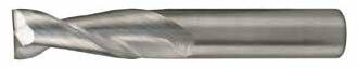
• Circular land reduces edge aggressiveness for varied speed and feed rates
• 2 Flutes effectively manage the large size and volume of chips produced during the aggressive machining process
• Excellent balance at high speeds and aggressive plunging capability
• Recommended for materials ≤ 150 Bhn (≤ 7 HRc)
TOLERANCES (inch)
1/4–3/8 DIAMETER
1/2–5/8 DIAMETER
= h 6
3/4–1 DIAMETER
= +0.0000/–0.00051 DCON = h 6
NON-FERROUS

TOLERANCES (inch)
1/4–3/8 DIAMETER
DC = +0.0000/–0.00035
DCON = h 6
1/2–5/8 DIAMETER
DC = +0.0000/–0.00043
DCON = h 6
3/4–1 DIAMETER
DC = +0.0000/–0.00051
DCON = h 6
NON-FERROUS
• Circular land reduces edge aggressiveness for varied speed and feed rates
• 2 Flutes effectively manage the large size and volume of chips produced during the aggressive machining process
• Excellent balance at high speeds and aggressive plunging capability
• Necked design with blended diameter transitions provide clearance to reach
• Recommended for materials ≤ 150 Bhn (≤ 7 HRc)
S-Carb

FRACTIONAL SERIES
• Circular land reduces edge aggressiveness for
• 2 Flutes effectively manage the large size and volume of chips produced during the aggressive machining process
• Excellent balance at high speeds and aggressive plunging capability
• Ball end design ideal for finishing operations in complex workpieces
• Recommended for materials ≤ 150 Bhn (≤ 7 HRc)
• Circular land reduces edge aggressiveness for varied speed and feed rates
• 2 Flutes effectively manage the large size and volume of chips produced during the aggressive machining process
• Excellent balance at high speeds and aggressive plunging capability
• Necked design with blended diameter transitions provide clearance to reach
• Ball end design ideal for finishing operations in complex workpieces
• Recommended for materials ≤ 150 Bhn (≤ 7 HRc)
TOLERANCES (inch)
1/8–3/16 DIAMETER
DC = +0.0000/–0.00032 DCON = h 6
= +.0005/–.0005
1/4–3/8 DIAMETER DC = +0.0000/–0.00035 DCON = h 6
= +.0005/–.0005
1/2–5/8 DIAMETER DC = +0.0000/–0.00043
= h 6 RE = +.0005/–.0005
3/4–1 DIAMETER
DC = +0.0000/–0.00051
DCON = h 6 RE = +.0005/–.0005
TOLERANCES (inch)
1/4–3/8 DIAMETER
DC = +0.0000/–0.00035
DCON = h 6
RE = +.0005/–.0005
1/2–5/8 DIAMETER
DC = +0.0000/–0.00043
DCON = h 6 RE = +.0005/–.0005
3/4–1 DIAMETER
DC = +0.0000/–0.00051
DCON = h 6
RE = +.0005/–.0005
Series 47, 47B, 47L, 47LB Fractional
ALUMINUM ALLOYS
2024, 5052, 5086, 6061, 6073, 7075
ALUMINUM DIE CAST ALLOYS (HIGH SILICONE)
PLASTICS
Polycarbonate, PVC, Polypropylene
Bhn (Brinell) HRc (Rockwell C) HRb (Rockwell B) HSM (High Speed Machining)
rpm = Vc x 3.82 / DC
ipm = Fz x 2 x rpm
reduce speed and feed for materials harder than listed reduce cut depth and feed by 50% for long flute and long reach tools reduce feed and Ae when finish milling (.02 x DC maximum) refer to the KYOCERA SGS APEX for complete technical information (www.kyocera-sgstool.com/apex)
47M
SERIES
• Circular land reduces edge aggressiveness for varied speed and feed rates
• 2 Flutes effectively manage the large size and volume of chips produced during the aggressive machining process
• Excellent balance at high speeds and aggressive plunging capability
• Recommended for materials ≤ 150 Bhn (≤ 7 HRc)
TOLERANCES (mm)
3 DIAMETER
DC = +0,000/–0,006
DCON = h 6
>3–6 DIAMETER
DC = +0,000/–0,008
DCON = h 6
>6–10 DIAMETER
DC = +0,000/–0,009
DCON = h 6
>10–18 DIAMETER
DC = +0,000/–0,012
DCON = h 6
>18–25 DIAMETER
DC = +0,000/–0,013
DCON = h 6
• Circular land reduces edge aggressiveness for varied speed and feed rates
• 2 Flutes effectively manage the large size and volume of chips produced during the aggressive machining process
• Excellent balance at high speeds and aggressive plunging capability
• Necked design with blended diameter transitions provide clearance to reach
• Recommended for materials ≤ 150 Bhn (≤ 7 HRc)
TOLERANCES (mm)
6 DIAMETER
DC = +0,000/–0,008
DCON = h 6
>6–10 DIAMETER
DC = +0,000/–0,009
DCON = h 6
>10–18 DIAMETER
DC = +0,000/–0,011
DCON = h 6
>18–20 DIAMETER
DC = +0,000/–0,013
DCON = h 6
TOLERANCES (mm)
3 DIAMETER
DC = +0,000/–0,006
DCON = h 6
RE = +0,0127/–0,0127
>3–6 DIAMETER
DC = +0,000/–0,008
DCON = h 6
RE = +0,0127/–0,0127
>6–10 DIAMETER
DC = +0,000/–0,009
DCON = h 6
RE = +0,0127/–0,0127
>10–18 DIAMETER
DC = +0,000/–0,012
DCON = h 6
RE = +0,0127/–0,0127
>18–25 DIAMETER
DC = +0,000/–0,013
DCON = h 6
RE = +0,0127/–0,0127
TOLERANCES (mm)
6 DIAMETER
DC = +0,000/–0,008
DCON = h 6
RE = +0,0127/–0,0127
>6–10 DIAMETER
DC = +0,000/–0,009
DCON = h 6
RE = +0,0127/–0,0127
>10–18 DIAMETER
DC = +0,000/–0,011
DCON = h 6
RE = +0,0127/–0,0127
>18–20 DIAMETER
DC = +0,000/–0,013
DCON = h 6
RE = +0,0127/–0,0127
RE = 1/2 Cutting Diameter (DC)
• Circular land reduces edge aggressiveness for varied speed and feed rates
• 2 Flutes effectively manage the large size and volume of chips produced during the aggressive machining process
• Excellent balance at high speeds and aggressive plunging capability
• Ball end design ideal for finishing operations in complex workpieces
• Recommended for materials ≤ 150 Bhn (≤ 7 HRc)
= 1/2 Cutting Diameter (DC)
• Circular land reduces edge aggressiveness for varied speed and feed rates
• 2 Flutes effectively manage the large size and volume of chips produced during the aggressive machining process
• Excellent balance at high speeds and aggressive plunging capability
• Necked design with blended diameter transitions provide clearance to reach
• Ball end design ideal for finishing operations in complex workpieces
• Recommended for materials ≤ 150
METRIC S-Carb
Series 47M, 47MB, 47ML, 47MLB Metric Hardness
ALUMINUM ALLOYS
2024, 5052, 5086, 6061, 6073, 7075
ALUMINUM DIE CAST ALLOYS
(HIGH SILICONE)
A-390, A-392, B- 390
COPPER ALLOYS
COPPER ALLOYS
Beryllium Copper
Manganese
PLASTICS
Bhn (Brinell) HRc (Rockwell C) HRb (Rockwell B) HSM (High Speed Machining) rpm = (Vc x 1000) / (DC x 3.14) mm/min = Fz x 2 x rpm reduce speed and feed for materials harder than listed reduce cut depth and feed by 50% for long flute and long reach tools reduce feed and Ae when finish milling (.02 x DC maximum) refer to the KYOCERA SGS APEX for complete technical information (www.kyocera-sgstool.com/apex)
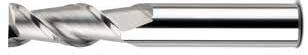
TOLERANCES (inch)
1/4–3/8 DIAMETER
DC = +0.0000/–0.00035
DCON = h 6
1/2–5/8 DIAMETER
DC = +0.0000/–0.00043
DCON = h 6
3/4–1 DIAMETER
DC = +0.0000/–0.00051
DCON = h 6
Contact your KSPT Sales Representative for more information on Corner
TOLERANCES (mm)
≤3 DIAMETER
DC = +0,000/–0,006
DCON = h 6
>3–6 DIAMETER
DC = +0,000/–0,008
DCON = h 6
>6–10 DIAMETER
DC = +0,000/–0,009
DCON = h 6
>10–18 DIAMETER
DC = +0,000/–0,011
DCON = h 6
>18–20 DIAMETER
DC = +0,000/–0,013
DCON = h 6
Contact your KSPT Sales Representative for
• Polished ski land with primary and secondary flute wall design minimizes chip interference by directing chips away from secondary flute
• Circular land allows for increased control at various speed and feed rates ultimately reducing chatter
• Recommended for materials ≤ 150 Bhn (≤ 7 HRc)
• Polished ski land with primary and secondary flute wall design minimizes chip interference by directing chips away from secondary flute
• Circular land allows for increased control at various speed and feed rates ultimately reducing chatter
• Recommended for materials ≤ 150 Bhn (≤ 7 HRc)
Ski-Carb
ALUMINUM ALLOYS
2024, 5052, 5086, 6061, 6073, 7075
ALUMINUM DIE CAST ALLOYS (HIGH SILICONE) A-390, A-392, B- 390
COPPER ALLOYS
COPPER ALLOYS
Beryllium Copper C110, Manganese Bronze, Tin Bronze
Bhn (Brinell) HRc (Rockwell C) HRb (Rockwell B) HSM (High Speed Machining) rpm = Vc x 3.82 / DC ipm = Fz x 2 x rpm reduce speed and feed for materials harder than listed reduce cut depth and feed by 50% for long flute and long reach tools reduce feed and Ae when finish milling (.02 x DC maximum) refer to the KYOCERA SGS APEX for complete technical information (www.kyocera-sgstool.com/apex)
ALUMINUM ALLOYS
2024, 5052, 5086, 6061, 6073, 7075
ALUMINUM DIE CAST ALLOYS
(HIGH SILICONE)
A-390, A-392, B- 390
COPPER ALLOYS
COPPER ALLOYS
PLASTICS
Bhn (Brinell) HRc (Rockwell C) HRb (Rockwell B) HSM (High Speed Machining) rpm = (Vc x 1000) / (DC x 3.14) mm/min = Fz x 2 x rpm reduce speed and feed for materials harder than listed reduce cut depth and feed by 50% for long flute and long reach tools reduce feed and Ae when finish milling (.02 x DC maximum) refer to the KYOCERA SGS APEX for complete technical information (www.kyocera-sgstool.com/apex)
Ski-Carb

• Polished ski land with primary and secondary flute wall design minimizes chip interference by directing chips away from secondary flute
• Circular land allows for increased control at various speed and feed rates ultimately reducing chatter
• Recommended for materials ≤ 150 Bhn (≤ 7 HRc)
Contact your KSPT representative for reach options.
TOLERANCES (inch)
1/4–3/8 DIAMETER
= +0.0000/–0.00035
= h 6
= +0.0000/–0.0020
1/2–5/8 DIAMETER
= +0.0000/–0.00043
= h 6
= +0.0000/–0.0020
3/4–1 DIAMETER DC = +0.0000/–0.00051
= h 6
NON-FERROUS
ALUMINUM ALLOYS
2024, 5052, 5086, 6061, 6073, 7075
ALUMINUM DIE CAST
ALLOYS (HIGH SILICONE)
COPPER ALLOYS
Aluminum Bronze Brass Naval Brass Red Brass
PLASTICS
ABS, Polycarbonate, PVC, Polypropylene
Bhn (Brinell) HRc (Rockwell C) HRb (Rockwell B) HSM (High Speed Machining)
rpm = Vc x 3.82 / DC
ipm = Fz x 2 x rpm
reduce speed and feed for materials harder than listed reduce cut depth and feed by 50% for long flute and long reach tools reduce feed and Ae when finish milling (.02 x DC maximum) refer to the KYOCERA SGS APEX for complete technical information (www.kyocera-sgstool.com/apex)
VALUE AT THE SPINDLE
Solid Car bide Tools
High Performance Drills

Hole Making
Speed & Feed Recommendations listed after each series
Taladrado
142P (3XD) 2 filos, refrigeración interna, 4 margen, 3XD
142P (5XD) 2 filos, refrigeración interna, 4 margen, 5XD
142P (8XD) 2 filos, refrigeración interna, 4 margen, 8XD
142P (12XD) 2 filos, refrigeración interna, 4 margen, 12XD
143M-S (3XD) 2 filos, refrigeracion interna, 2 margen, 3XD
143M-S (5XD) 2 filos, refrigeracion interna, 2 margen, 5XD
141K (5xD) 3 filos, refrigeración interna, 3 margen, 5xD
131N (3xD) 3 filos, refrigeración externa, 3 margen, 3xD
131N (5xD) 3 filos, refrigeración externa, 3 margen, 5xD
135 (3xD) 2 filos, refrigeración externa, 4 margen, 3xD
135 (5xD) 2 filos, refrigeración externa, 4 margen, 5xD
146U (3xD) 2 filos, refrigeración interna, 4 margen, 3xD
146U (5xD) 2 filos, refrigeración interna, 4 margen, 5xD
136U (2xD) 2 filos, refrigeración externa, 4 margen, 2xD
De 8 caras CFRP 120 2 filos, refrigeración externa, 4 margen, CFRP
Recomendaciones de velocidades y avances mostradas tras cada serie
Outils de perçage
Recommandations de vitesse et avance indiquées après chaque série
Bohren
HOCHLEISTUNGSBOHRER SERIE BESCHREIBUNG
Hi-PerCarb
142P (3XD) Doppelfasenbohrer mit 4 Schneiden und Innenkühlung, 3xD
142P (3XD) Doppelfasenbohrer mit 4 Schneiden und Innenkühlung, 5xD
142P (3XD) Doppelfasenbohrer mit 4 Schneiden und Innenkühlung, 8xD
142P (12XD) Doppelfasenbohrer mit 4 Schneiden und Innenkühlung, 12xD
143M-S (3XD) 2 Einfasenbohrer mit 2 Schneiden und Innenkühlung, 3xD
143M-S (5XD) 2 Einfasenbohrer mit 2 Schneiden und Innenkühlung, 5xD
141K (5xD) Dreifasenbohrer 5xD mit 3 Schneiden und Innenkühlung
131N (3xD) Dreifasenbohrer 3xD mit 3 Schneiden und Außenkühlung
131N (5xD) Dreifasenbohrer 5xD mit 3 Schneiden und Außenkühlung
135 (3xD) Doppelfasenbohrer 3xD mit 4 Schneiden und Außenkühlung
135 (5xD) Doppelfasenbohrer 5xD mit 4 Schneiden und Außenkühlung
146U (3xD) Doppelfasenbohrer 3xD mit 4 Schneiden und Innenkühlung
146U (5xD) Doppelfasenbohrer 5xD mit 4 Schneiden und Innenkühlung
136U (2xD) Doppelfasenbohrer 2xD mit 4 Schneiden und Außenkühlung
120 Doppelfasenbohrer CFRP mit 4 Schneiden und Außenkühlung
Empfehlungen für Drehzahl & Vorschub im Anhang zu jeder Serie
Drill Matrix


Attributes
Material hardness and machinability affect speed, feed, and cut depths. For dimensional and finish quality, a low TIR of the tool-holder assembly in the machine is critical: less than 0.1% drill diameter is preferred. Spot drilling is not necessary in most situations if the drilling surface is machined flat ; spot drill point angle should be greater than drill point angle. Liquid coolant (internal or external) such as oil based or synthetic is highly recommended for all drilling applications. For proper cooling, lubrication and chip evacuation, ensure the coolant is supplied throughout the entire depth of the hole. When liquid coolant cannot be applied for applications such as plastics or composites, clear the swarf with air or vacuum. Depending on material machinability, a peck cycle may be neccesary for external coolant drills beyond 2x or 3x depths.
Drilling Operations
SGS COOLANT RECOMMENDATIONS
Coolant Recommendations
◾ Coolant works to mobilize chips away from the cut zone, reduce the heat created during the cutting process and minimize friction.
◾ It is important to optimize the coolant pressure and position in order to gain the full benefits coolant offers the cutting process.
◾ Proper coolant application promotes greater operating parameters, greater material removal rates, improved surface finishes, predictable tool life, reduced power consumption and reduced cycle times.
◾ Pressure is important, but more importantly is consistency of the pressure and application onto the tool; intermittent cooling of carbide leads to thermal stressing of the material and the formation of “microcracks.”
◾ Proper cleanliness and filtration of coolants is important in order for the coolant to maintain its beneficial properties, and also to avoid a reduction in coolant pressure or the possibility of clogging the coolant channels in coolant through drills.
RECOMMENDED COOLANT PRESSURE BY
RECOMMENDED COOLANT PRESSURE BY DIAMETER –
RECOMMENDED
RECOMMENDED COOLANT PRESSURE BY DIAMETER – bar
LARGE TIP – LOW VELOCITY NO COVERAGE AT MAXIMUM DEPTH
SMALL TIP – HIGH VELOCITY COMPLETE COVERAGE
◾ Reducing the nozzle size helps maximize the cooling benefits of the unique double margin design on the Hi-PerCarb drill by increasing velocity. Aim the nozzles in line with the secondary flute located between the two margins as well as the flute for best results.
SPANISH
◾ El líquido de refrigeración actúa movilizando las virutas fuera de la zona de corte, disminuyendo el calor generado durante el proceso de corte y minimizando la fricción.
◾ Es importante optimizar la presión de la refrigeración y la posición para poder obtener todos los beneficios del refrigerante durante el proceso de corte.
◾ Una aplicación apropiada de la refrigeración fomenta mayores parámetros de operación, mayores índices de eliminación de material, acabados de superficie mejorados, una duración de la herramienta más predecible, bajo consumo de energía y un tiempo de ciclo reducido.
◾ La presión del refrigerante es importante, pero lo es más el flujo continuo aplicado a la herramienta; una refrigeración intermitente en el carburo puede ocasionar un estrés térmico en el material y la formación de “micro-fisuras”.
◾ Una limpieza y filtración adecuadas son importantes para que el refrigerante mantenga sus propiedades y beneficios; por otra parte, se evita la reducción de la presión o la posibilidad de obstruir los canales de refrigeración de la broca.
Recomendaciones en operacion de taladrado
PRESIÓN DE REFRIGERACIÓN RECOMENDADA POR DIÁMETRO – psi
PRESIÓN DE REFRIGERACIÓN RECOMENDADA POR DIÁMETRO – psi
DE LA BROCA (mm)
DE LA BROCA (mm)
PRESIÓN DE REFRIGERACIÓN RECOMENDADA POR DIÁMETRO – bar
PRESIÓN DE REFRIGERACIÓN RECOMENDADA POR DIÁMETRO – bar
(mm)
PUNTA GRANDE – BAJA VELOCIDAD SIN ALCANCE A PROFUNDIDAD MÁXIMA
PUNTA GRANDE – BAJA VELOCIDAD SIN ALCANCE A PROFUNDIDAD MÁXIMA
PUNTA PEQUEÑA – ALTA VELOCIDAD COMPLETO ALCANCE
PUNTA PEQUEÑA – ALTA VELOCIDAD COMPLETO ALCANCE
◾ Reducir el tamaño de la boquilla ayuda a maximizar los beneficios de refrigeración del exclusivo diseño de doble margen de la broca. Hi-PerCarb aumentando la velocidad. Coloque las boquillas en línea con el segundo filo que se encuentra entre los dos márgenes y también el filo para obtener mejores resultados.
Opérations de perçage
FRENCH
Recommandations en matière de refroidissement
◾ Le liquide de refroidissement sert à éloigner les copeaux de la zone de coupe, à réduire la chaleur dégagée durant la coupe et à minimiser la friction.
◾ Il est important d’optimiser la pression et la position du réfrigérant pour en retirer les bénéfices maximums durant la coupe.
◾ L’application adéquate de réfrigérant se traduit par des paramètres opératoires supérieurs, des taux d'élimination supérieurs des matériaux, de plus belles finitions des surfaces, une durée de vie des outils prévisible, moins de consommation d’énergie et des temps de cycle réduits.
◾ La pression est importante, mais une pression régulière et l’application sur l’outil sont des facteurs encore plus importants ; le refroidissement intermittent du carbure se traduit par des contraintes thermiques pour le matériau et la formation de microfissures.
◾ La propreté et le filtrage adéquats des réfrigérants sont importants pour qu'ils conservent leur propriétés, mais aussi pour éviter la réduction de pression du réfrigérant ou le risque d’obturation des conduits à réfrigérant dans les perceuses à réfrigérant intégré.
POINTE LARGE – BASSE VITESSE PAS DE COUVERTURE À LA PROFONDEUR MAXIMUM
POINTE LARGE – BASSE VITESSE PAS DE COUVERTURE À LA PROFONDEUR MAXIMUM
PRESSION DE LIQUIDE DE REFROIDISSEMENT RECOMMANDÉE DIAMÈTRE – psi
PRESSION DE LIQUIDE DE REFROIDISSEMENT RECOMMANDÉE DIAMÈTRE – psi
DE PERÇAGE (mm)
DE PERÇAGE (mm)
PRESSION DE LIQUIDE DE REFROIDISSEMENT RECOMMANDÉE DIAMÈTRE – bar
DE LIQUIDE DE REFROIDISSEMENT RECOMMANDÉE DIAMÈTRE – bar
POINTE FINE – GRANDE VITESSE COUVERTURE COMPLÈTE
POINTE FINE – GRANDE VITESSE COUVERTURE COMPLÈTE
◾ La réduction de la taille de l’embout permet de maximiser les bienfaits du refroidissement du concept à double listel original de la perceuse Hi-PerCarb en augmentant la vitesse. Pour les meilleurs résultats, orientez les embouts dans l'axe de la goujure secondaire située entre les deux listels, de même que la goujure primaire.
◾ Kühlmittel dienen dazu, die Späne aus dem Schneidenbereich zu entfernen, die beim Schneiden erzeugte Wärme abzutransportieren und die Reibung zu verringern.
◾ Es kommt darauf an, den Kühlschmiermitteldruck und die Zufuhr zu optimieren, um alle Vorteile beim Bohren nutzen zu können.
◾ Der richtige Kühlschmiermitteleinsatz ermöglicht höhere Schnittparameter, höheren Materialabtrag, bessere Oberflächengüte, vorhersehbare Standzeiten und geringere Leistungsaufnahme und Laufzeiten.
◾ Der Druck ist wichtig, aber wichtiger ist dessen Konstanz und die Zufuhr zum Werkzeug. Unterbrochene Kühlung des Hartmetalls führt zur thermischen Belastung und Bildung von “Mikrorissen”.
◾ Kühlmitte sind sauber zu halten und zu filtern, damit die Qualität des Kühlmittels erhalten bleibt und der Kühlmitteldruck durch Verstopfung der Kühlmittelkanäle im Bohrer nicht absinkt.
EMPFOHLENER KÜHLSCHMIERMITTELDRUCK NACH DURCHMESSER – psi
EMPFOHLENER KÜHLSCHMIERMITTELDRUCK NACH DURCHMESSER – psi
(mm)
(mm)
EMPFOHLENER KÜHLMITTELDRUCK NACH DURCHMESSER – bar
EMPFOHLENER KÜHLMITTELDRUCK NACH DURCHMESSER – bar
(mm)
BREITE QUERSCHNEIDE – GERINGE DREHZAHL
KEINE VOLLSTÄNDIGE BENETZUNG BEI MAX. BOHRUNGSTIEFE
BREITE QUERSCHNEIDE – GERINGE DREHZAHL KEINE VOLLSTÄNDIGE BENETZUNG BEI MAX. BOHRUNGSTIEFE
SCHMALE QUERSCHNEIDE – HOHE DREHZAHL VOLLSTÄNDIGE BENETZUNG
SCHMALE QUERSCHNEIDE – HOHE DREHZAHL VOLLSTÄNDIGE BENETZUNG
◾ Durch Verringern der Düsengröße können die vorteilhaften Eigenschaften der Doppelfase genutzt werden, um die Drehzahl des Hi-PerCarb-Bohrers zu steigern. Richten Sie die Düsen auf die Nebennut zwischen beiden Fasen sowie auf die Schneiden aus, um beste Ergebnisse zu erzielen.
Hi-PerCarb
142P 3xD
& METRIC SERIES
• High-performance point design stabilizes on entry for exceptional hole size and cylindricity while also allowing for low thrust force and extended tool life
• Internal coolant hole improves coolant flow to extend tool life and aid in chip evacuation
• 4-margin design improves hole straightness and roundness while providing improved stability for difficult applications like cross holes and when exiting on angle
• Proprietary Ti-NAMITE-X coating and industry leading carbide substrate provides exceptional wear resistance and toughness for demanding applications
• Recommended for materials ≤ 50HRc (475 Bhn)

continued on next page
TOLERANCES (inch)
≤.1181 DIAMETER
DC = +.00008/+.00047
DCON = h 6
>.1181–.2362 DIAMETER
DC = +.00016/+.00063
DCON = h 6
>.2362–.3937 DIAMETER
DC = +.00024/+.00083
DCON = h 6
>.3937–.7087 DIAMETER
DC = +.00028/+.00098
DCON = h 6
>.7087–1.1811 DIAMETER
DC = +.00031/+.00114
DCON = h 6
TOLERANCES (mm)
≤3 DIAMETER
DC = +0,002/+0,012
DCON = h 6
>3–6 DIAMETER
DC = +0,004/+0,016
DCON = h 6
>6–10 DIAMETER
DC = +0,006/+0,021
DCON = h 6
>10–18 DIAMETER
DC = +0,007/+0,025
DCON = h 6
>18–30 DIAMETER
DC = +0,008/+0,029
DCON = h 6
Hi-PerCarb
142P 3xD
& METRIC SERIES
CONTINUED
• High-performance point design stabilizes on entry for exceptional hole size and cylindricity while also allowing for low thrust force and extended tool life
• Internal coolant hole improves coolant flow to extend tool life and aid in chip evacuation
• 4-margin design improves hole straightness and roundness while providing improved stability for difficult applications like cross holes and when exiting on angle
• Proprietary Ti-NAMITE-X coating and industry leading carbide substrate provides exceptional wear resistance and toughness for demanding applications
• Recommended for materials ≤ 50HRc (475 Bhn)
TOLERANCES (inch)
≤.1181 DIAMETER
DC = +.00008/+.00047
DCON = h 6
>.1181–.2362 DIAMETER
DC = +.00016/+.00063
DCON = h 6
>.2362–.3937 DIAMETER
DC = +.00024/+.00083
DCON = h 6
>.3937–.7087 DIAMETER
DC = +.00028/+.00098
DCON = h 6
>.7087–1.1811 DIAMETER
DC = +.00031/+.00114
DCON = h 6
TOLERANCES (mm)
≤3 DIAMETER
DC = +0,002/+0,012
DCON = h 6
>3–6 DIAMETER
DC = +0,004/+0,016
DCON = h 6
>6–10 DIAMETER
DC = +0,006/+0,021
DCON = h 6
>10–18 DIAMETER
DC = +0,007/+0,025
DCON = h 6
>18–30 DIAMETER
DC = +0,008/+0,029
DCON = h 6
• High-performance point design stabilizes on entry for exceptional hole size and cylindricity while also allowing for low thrust force and extended tool life
• Internal coolant hole improves coolant flow to extend tool life and aid in chip evacuation
• 4 margin design improves hole straightness and roundness while providing improved stability for difficult applications like cross holes and when exiting on angle
• Proprietary TINAMITE-X coating and industry leading carbide substrate provides exceptional wear resistance and toughness for demanding applications
• Recommended for materials ≤50HRc (475 Bhn)
Hi-PerCarb
142P 5xD
CONTINUED
• High-performance point design stabilizes on entry for exceptional hole size and cylindricity while also allowing for low thrust force and extended tool life
• Internal coolant hole improves coolant flow to extend tool life and aid in chip evacuation
• 4-margin design improves hole straightness and roundness while providing improved stability for difficult applications like cross holes and when exiting on angle
• Proprietary Ti-NAMITE-X coating and industry leading carbide substrate provides exceptional wear resistance and toughness for demanding applications
• Recommended for materials ≤ 50HRc (475 Bhn)
TOLERANCES (inch)
≤.1181 DIAMETER
DC = +.00008/+.00047
DCON = h 6
>.1181–.2362 DIAMETER
DC = +.00016/+.00063
DCON = h 6
>.2362–.3937 DIAMETER
DC = +.00024/+.00083
DCON = h 6
>.3937–.7087 DIAMETER
DC = +.00028/+.00098
DCON = h 6
>.7087–1.1811 DIAMETER
DC = +.00031/+.00114
DCON = h 6
TOLERANCES (mm)
≤3 DIAMETER
DC = +0,002/+0,012
DCON = h 6
>3–6 DIAMETER
DC = +0,004/+0,016
DCON = h 6
>6–10 DIAMETER
DC = +0,006/+0,021
DCON = h 6
>10–18 DIAMETER
DC = +0,007/+0,025
DCON = h 6
>18–30 DIAMETER
DC = +0,008/+0,029
DCON = h 6
Hi-PerCarb
142P 8xD
FRACTIONAL & METRIC SERIES
CONTINUED
• High-performance point design stabilizes on entry for exceptional hole size and cylindricity while also allowing for low thrust force and extended tool life
• Internal coolant hole improves coolant flow to extend tool life and aid in chip evacuation
• 4-margin design improves hole straightness and roundness while providing improved stability for difficult applications like cross holes and when exiting on angle
• Proprietary Ti-NAMITE-X coating and industry leading carbide substrate provides exceptional wear resistance and toughness for demanding applications
• Recommended for materials ≤ 50HRc (475 Bhn)
on next page
TOLERANCES (inch)
≤.1181 DIAMETER
DC = +.00008/+.00047
DCON = h 6
>.1181–.2362 DIAMETER
DC = +.00016/+.00063
DCON = h 6
>.2362–.3937 DIAMETER
DC = +.00024/+.00083
DCON = h 6
>.3937–.7087 DIAMETER
DC = +.00028/+.00098
DCON = h 6
>.7087–1.1811 DIAMETER
DC = +.00031/+.00114
DCON = h 6
TOLERANCES (mm)
≤3 DIAMETER
DC = +0,002/+0,012
DCON = h 6
>3–6 DIAMETER
DC = +0,004/+0,016
DCON = h 6
>6–10 DIAMETER
DC = +0,006/+0,021
DCON = h 6
>10–18 DIAMETER
DC = +0,007/+0,025
DCON = h 6
>18–30 DIAMETER
DC = +0,008/+0,029
DCON = h 6
Hi-PerCarb
142P 12xD
FRACTIONAL & METRIC SERIES
• High-performance point design stabilizes on entry for exceptional hole size and cylindricity while also allowing for low thrust force and extended tool life
• Internal coolant hole improves coolant flow to extend tool life and aid in chip evacuation
• 4-margin design improves hole straightness and roundness while providing improved stability for difficult applications like cross holes and when exiting on angle
• Proprietary Ti-NAMITE-X coating and industry leading carbide substrate provides exceptional wear resistance and toughness for demanding applications
• Recommended for materials ≤ 50HRc (475 Bhn)
continued on next page
TOLERANCES (inch)
≤.1181 DIAMETER
DC = +.00008/+.00047
DCON = h 6
>.1181–.2362 DIAMETER
DC = +.00016/+.00063
DCON = h 6
>.2362–.3937 DIAMETER
DC = +.00024/+.00083
DCON = h 6
>.3937–.7087 DIAMETER
DC = +.00028/+.00098
DCON = h 6
>.7087–1.1811 DIAMETER
DC = +.00031/+.00114
DCON = h 6
TOLERANCES (mm)
≤3 DIAMETER
DC = +0,002/+0,012
DCON = h 6
>3–6 DIAMETER
DC = +0,004/+0,016
DCON = h 6
>6–10 DIAMETER
DC = +0,006/+0,021
DCON = h 6
>10–18 DIAMETER
DC = +0,007/+0,025
DCON = h 6
>18–30 DIAMETER
DC = +0,008/+0,029
DCON = h 6
0.3425
continued on next page
Hi-PerCarb
142P 12xD
FRACTIONAL & METRIC SERIES
CONTINUED
• High-performance point design stabilizes on entry for exceptional hole size and cylindricity while also allowing for low thrust force and extended tool life
• Internal coolant hole improves coolant flow to extend tool life and aid in chip evacuation
• 4-margin design improves hole straightness and roundness while providing improved stability for difficult applications like cross holes and when exiting on angle
• Proprietary Ti-NAMITE-X coating and industry leading carbide substrate provides exceptional wear resistance and toughness for demanding applications
• Recommended for materials ≤ 50HRc (475 Bhn)
on
TOLERANCES (inch)
≤.1181 DIAMETER
DC = +.00008/+.00047
DCON = h 6
>.1181–.2362 DIAMETER
DC = +.00016/+.00063
DCON = h 6
>.2362–.3937 DIAMETER
DC = +.00024/+.00083
DCON = h 6
>.3937–.7087 DIAMETER
DC = +.00028/+.00098
DCON = h 6
>.7087–1.1811 DIAMETER
DC = +.00031/+.00114
DCON = h 6
TOLERANCES (mm)
≤3 DIAMETER
DC = +0,002/+0,012
DCON = h 6
>3–6 DIAMETER
DC = +0,004/+0,016
DCON = h 6
>6–10 DIAMETER
DC = +0,006/+0,021
DCON = h 6
>10–18 DIAMETER
DC = +0,007/+0,025
DCON = h 6
>18–30 DIAMETER
DC = +0,008/+0,029
DCON = h 6
Hi-PerCarb
CARBON STEELS
1018, 1040, 1080, 1090, 10L50, 1140, 1212, 12L15, 1525, 1536
ALLOY STEELS
4140, 4150, 4320, 5120, 5150, 8630, 86L20, 50100
TOOL STEELS
A2, D2, H13, L2, M2, P20, S7, T15, W2
STAINLESS STEELS (FREE MACHINING)
303, 416, 420F, 430F, 440F
STAINLESS STEELS (DIFFICULT)
304, 316, 321, 13-8 PH, 15-5PH, 17-4 PH, Custom 450
K CAST IRONS Gray, Malleable, Ductile
ALUMINUM ALLOYS
2017, 2024, 356, 6061, 7075
COPPER ALLOYS
Alum Bronze, C110, Muntz Brass
HIGH TEMP ALLOYS (NICKEL , COBALT, IRON BASE)
Inconel 601, 617, 625, Incoloy, Monel 400, Rene, Waspaloy
TITANIUM ALLOYS
Pure Titanium, Ti6Al4V, Ti6Al2Sn4Zr2Mo, Ti4Al4Mo2Sn0.5Si, Ti-6Al4V
H TOOL STEELS
A2, D2, H13, L2, M2, P20, S7, T15, W2 ≤ 475 Bhn or
(68-102)
Bhn (Brinell) HRc (Rockwell C) HRb (Rockwell B) rpm = Vc x 3.82 / DC ipm = Fr x RPM
reduce speed and feed for materials harder than listed refer to the KYOCERA SGS APEX for complete technical information (www.kyocera-sgstool.com/apex)
CARBON STEELS
1018, 1040, 1080, 1090, 10L50, 1140, 1212, 12L15, 1525, 1536
275 Bhn
ALLOY STEELS
4140, 4150, 4320, 5120, 5150, 8630, 86L20, 50100
TOOL STEELS
A2, D2, H13, L2, M2, P20, S7, T15, W2
STAINLESS STEELS (FREE MACHINING)
303, 416, 420F, 430F, 440F
STAINLESS STEELS (DIFFICULT)
304, 316, 321, 13-8 PH, 15-5PH, 17-4 PH, Custom 450
K CAST IRONS Gray, Malleable, Ductile
ALUMINUM ALLOYS
2017, 2024, 356, 6061, 7075
COPPER ALLOYS
Alum Bronze, C110, Muntz Brass
HIGH TEMP ALLOYS
(Nickel , Cobalt, Iron Base)
Inconel 601, 617, 625, Incoloy, Monel 400, Rene, Waspaloy
TITANIUM ALLOYS
Pure Titanium, Ti6Al4V, Ti6Al2Sn4Zr2Mo, Ti4Al4Mo2Sn0.5Si, Ti-6Al4V
H TOOL STEELS
A2, D2, H13, L2, M2, P20, S7, T15, W2
(Brinell) HRc (Rockwell C) HRb (Rockwell B)
rpm = (Vc x 1000) / (DC x 3.14)
mm/min = Fr x RPM
reduce speed and feed for materials harder than listed refer to the KYOCERA SGS APEX for complete technical information (www.kyocera-sgstool.com/apex)
Hi-PerCarb
143M-S 3xD

FRACTIONAL & METRIC SERIES
• Coolant through design improves coolant flow to extend tool life and aid in chip evacuation
• Eccentric 2-margin design reduces frictional heat and minimizes material adhesion to the margins without weakening the drill
• Computer controlled edge honing protects against chip damage
• High-performance point design stabilizes on contact for exceptional hole size and cylindricity allowing for low thrust force and extended tool life
• SGS Ti-NAMITE-A coating provides exceptional wear and erosion resistance when drilling heat resisting alloys like Inconel, Stainless Steel, and Titanium Alloys
• Recommended for materials ≤ 50HRc (475 Bhn)
TOLERANCES (inch)
≤.1181 DIAMETER
DC = +.00008/+.00047
DCON = h 6
>.1181–.2362 DIAMETER
DC = +.00016/+.00063
DCON = h 6
>.2362–.3937 DIAMETER
DC = +.00024/+.00083
DCON = h 6
>.3937–.7087 DIAMETER
DC = +.00028/+.00098
DCON = h 6
>.7087–1.1811 DIAMETER
DC = +.00031/+.00114
DCON = h 6
TOLERANCES (mm)
≤3 DIAMETER
DC = +0,002/+0,012
DCON = h 6
>3–6 DIAMETER
DC = +0,004/+0,016
DCON = h 6
>6–10 DIAMETER
DC = +0,006/+0,021
DCON = h 6
>10–18 DIAMETER
DC = +0,007/+0,025
DCON = h 6
>18–30 DIAMETER
DC = +0,008/+0,029
DCON = h 6
143M-S 3xD
continued on next page
143M-S 3xD
& METRIC SERIES
CONTINUED
• Coolant through design improves coolant flow to extend tool life and aid in chip evacuation
• Eccentric 2-margin design reduces frictional heat and minimizes material adhesion to the margins without weakening the drill
• Computer controlled edge honing protects against chip damage
• High-performance point design stabilizes on contact for exceptional hole size and cylindricity allowing for low thrust force and extended tool life
• SGS Ti-NAMITE-A coating provides exceptional wear and erosion resistance when drilling heat resisting alloys like Inconel, Stainless Steel, and Titanium Alloys
• Recommended for materials ≤ 50HRc (475 Bhn)
TOLERANCES (inch)
≤.1181 DIAMETER
DC = +.00008/+.00047
DCON = h 6
>.1181–.2362 DIAMETER
DC = +.00016/+.00063
DCON = h 6
>.2362–.3937 DIAMETER
DC = +.00024/+.00083
DCON = h 6
>.3937–.7087 DIAMETER
DC = +.00028/+.00098
DCON = h 6
>.7087–1.1811 DIAMETER
DC = +.00031/+.00114
DCON = h 6
TOLERANCES (mm)
≤3 DIAMETER
DC = +0,002/+0,012
DCON = h 6
>3–6 DIAMETER
DC = +0,004/+0,016
DCON = h 6
>6–10 DIAMETER
DC = +0,006/+0,021
DCON = h 6
>10–18 DIAMETER
DC = +0,007/+0,025
DCON = h 6
>18–30 DIAMETER
DC = +0,008/+0,029
DCON = h 6
143M-S 3xD
Hi-PerCarb
143M-S 5xD
FRACTIONAL & METRIC SERIES
• Coolant through design improves coolant flow to extend tool life and aid in chip evacuation
• Eccentric 2-margin design reduces frictional heat and minimizes material adhesion to the margins without weakening the drill
• Computer controlled edge honing protects against chip damage
• High-performance point design stabilizes on contact for exceptional hole size and cylindricity allowing for low thrust force and extended tool life
• SGS Ti-NAMITE-A coating provides exceptional wear and erosion resistance when drilling heat resisting alloys like Inconel, Stainless Steel, and Titanium Alloys
• Recommended for materials ≤ 50HRc (475 Bhn)
TOLERANCES (inch)
≤.1181 DIAMETER
DC = +.00008/+.00047
DCON = h 6
>.1181–.2362 DIAMETER
DC = +.00016/+.00063
DCON = h 6
>.2362–.3937 DIAMETER
DC = +.00024/+.00083
DCON = h 6
>.3937–.7087 DIAMETER
DC = +.00028/+.00098
DCON = h 6
>.7087–1.1811 DIAMETER
DC = +.00031/+.00114
DCON = h 6
TOLERANCES (mm)
≤3 DIAMETER
DC = +0,002/+0,012
DCON = h 6
>3–6 DIAMETER
DC = +0,004/+0,016
DCON = h 6
>6–10 DIAMETER
DC = +0,006/+0,021
DCON = h 6
>10–18 DIAMETER
DC = +0,007/+0,025
DCON = h 6
>18–30 DIAMETER
DC = +0,008/+0,029
DCON = h 6
143M-S 5xD
continued on next page
Hi-PerCarb
143M-S 5xD
FRACTIONAL & METRIC SERIES
CONTINUED
• Coolant through design improves coolant flow to extend tool life and aid in chip evacuation
• Eccentric 2-margin design reduces frictional heat and minimizes material adhesion to the margins without weakening the drill
• Computer controlled edge honing protects against chip damage
• High-performance point design stabilizes on contact for exceptional hole size and cylindricity allowing for low thrust force and extended tool life
• SGS Ti-NAMITE-A coating provides exceptional wear and erosion resistance when drilling heat resisting alloys like Inconel, Stainless Steel, and Titanium Alloys
• Recommended for materials ≤ 50HRc (475 Bhn)
TOLERANCES (inch)
≤.1181 DIAMETER
DC = +.00008/+.00047
DCON = h 6
>.1181–.2362 DIAMETER
DC = +.00016/+.00063
DCON = h 6
>.2362–.3937 DIAMETER
DC = +.00024/+.00083
DCON = h 6
>.3937–.7087 DIAMETER
DC = +.00028/+.00098
DCON = h 6
>.7087–1.1811 DIAMETER
DC = +.00031/+.00114
DCON = h 6
TOLERANCES (mm)
≤3 DIAMETER
DC = +0,002/+0,012
DCON = h 6
>3–6 DIAMETER
DC = +0,004/+0,016
DCON = h 6
>6–10 DIAMETER
DC = +0,006/+0,021
DCON = h 6
>10–18 DIAMETER
DC = +0,007/+0,025
DCON = h 6
>18–30 DIAMETER
DC = +0,008/+0,029
DCON = h 6
Hi-PerCarb
CARBON STEELS
1018, 1040, 1080, 1090, 10L50, 1140, 1212, 12L15, 1525, 1536
ALLOY STEELS
4140, 4150, 4320, 5120, 5150, 8630, 86L20, 50100
TOOL STEELS
A2, D2, H13, L2, M2, P20, S7, T15, W2
STAINLESS STEELS (FREE MACHINING)
303, 416, 420F, 430F, 440F
STAINLESS STEELS (DIFFICULT)
304, 316, 321, 13-8 PH, 15-5PH, 17-4 PH, Custom 450
K CAST IRONS Gray, Malleable, Ductile
HIGH TEMP ALLOYS (NICKEL , COBALT, IRON BASE)
Inconel 601, 617, 625, Incoloy, Monel 400, Rene, Waspaloy
TITANIUM ALLOYS
Pure Titanium, Ti6Al4V, Ti6Al2Sn4Zr2Mo, Ti4Al4Mo2Sn0.5Si, Ti-6Al4V
Bhn (Brinell) HRc (Rockwell C) HRb (Rockwell B) rpm = Vc x 3.82 / DC
ipm = Fr x RPM
reduce speed and feed for materials harder than listed refer to the KYOCERA SGS APEX for complete technical information (www.kyocera-sgstool.com/apex)
CARBON STEELS
1018, 1040, 1080, 1090, 10L50, 1140, 1212, 12L15, 1525, 1536
275 Bhn or
ALLOY STEELS
4140, 4150, 4320, 5120, 5150, 8630, 86L20, 50100
TOOL STEELS
A2, D2, H13, L2, M2, P20, S7, T15, W2
STAINLESS STEELS (FREE MACHINING)
303, 416, 420F, 430F, 440F
M
STAINLESS STEELS (DIFFICULT)
304, 316, 321, 13-8 PH, 15-5PH, 17-4 PH, Custom 450
K CAST IRONS
Gray, Malleable, Ductile
HIGH TEMP ALLOYS
(Nickel , Cobalt, Iron Base)
Inconel 601, 617, 625, Incoloy, Monel 400, Rene, Waspaloy
TITANIUM ALLOYS
Pure Titanium, Ti6Al4V, Ti6Al2Sn4Zr2Mo, Ti4Al4Mo2Sn0.5Si, Ti-6Al4V
Bhn (Brinell) HRc (Rockwell C) HRb (Rockwell B)
rpm = (Vc x 1000) / (DC x 3.14)
mm/min = Fr x RPM
reduce speed and feed for materials harder than listed refer to the KYOCERA SGS APEX for complete technical information (www.kyocera-sgstool.com/apex)
Hi-PerCarb
141K 5xD
FRACTIONAL & METRIC SERIES
• 3-margin design improves hole stability and size control while providing superior finish, roundness and cylindricity
• Self-stabilizing pyramid point design stabilizes the drill on contact with the workpiece
• Open flute structure efficiently transports chips while maintaining strength at high feed rates
• Sculpted gash allows chips to easily flow away from the drill center
• Recommended for materials ≤ 43 HRc (≤ 400 Bhn)

continued on next page
TOLERANCES (inch)
≤.1181 DIAMETER
DC = +.00008/+.00047
DCON = h 6
>.1181–.2362 DIAMETER
DC = +.00016/+.00063
DCON = h 6
>.2362–.3937 DIAMETER
DC = +.00024/+.00083
DCON = h 6
>.3937–.7087 DIAMETER
DC = +.00028/+.00098
DCON = h 6
>.7087–1.1811 DIAMETER
DC = +.00031/+.00114
DCON = h 6
TOLERANCES (mm)
≤3 DIAMETER
DC = +0,002/+0,012
DCON = h 6
>3–6 DIAMETER
DC = +0,004/+0,016
DCON = h 6
>6–10 DIAMETER
DC = +0,006/+0,021
DCON = h 6
>10–18 DIAMETER
DC = +0,007/+0,025
DCON = h 6
0.3594
Hi-PerCarb
141K 5xD
FRACTIONAL & METRIC SERIES
CONTINUED
• 3-margin design improves hole stability and size control while providing superior finish, roundness and cylindricity
• Self-stabilizing pyramid point design stabilizes the drill on contact with the workpiece
• Open flute structure efficiently transports chips while maintaining strength at high feed rates
• Sculpted gash allows chips to easily flow away from the drill center
• Recommended for materials ≤ 43 HRc (≤ 400 Bhn)
continued on next page
TOLERANCES (inch)
≤.1181 DIAMETER
DC = +.00008/+.00047
DCON = h 6
>.1181–.2362 DIAMETER
DC = +.00016/+.00063
DCON = h 6
>.2362–.3937 DIAMETER
DC = +.00024/+.00083
DCON = h 6
>.3937–.7087 DIAMETER
DC = +.00028/+.00098
DCON = h 6
>.7087–1.1811 DIAMETER
DC = +.00031/+.00114
DCON = h 6
TOLERANCES (mm)
≤3 DIAMETER
DC = +0,002/+0,012
DCON = h 6
>3–6 DIAMETER
DC = +0,004/+0,016
DCON = h 6
>6–10 DIAMETER
DC = +0,006/+0,021
DCON = h 6
>10–18 DIAMETER
DC = +0,007/+0,025
DCON = h 6
Hi-PerCarb
A48: CLASS 30, 35, 40 SAE J431C: GRADE 3000
MALLEABLE CAST IRON FERRITIC ASTM A220: GRADE 40010
SAE J158: GRADE M4504
CAST IRON MARTENSITE
ASTM A220: GRADE 90001
SAE J158: GRADE M8501
Bhn (Brinell) HRc (Rockwell C) rpm = Vc x 3.82 / DC ipm = Fr x rpm reduce speed and feed for materials harder than listed refer to the KYOCERA SGS APEX for complete technical information (www.kyocera-sgstool.com/apex)
Hi-PerCarb
(Brinell) HRc (Rockwell C) rpm = (Vc x 1000) / (DC x 3.14) mm/min = Fr x rpm reduce speed and feed for materials
TOLERANCES (inch)
≤.1181 DIAMETER
DC = +.00008/+.00047
DCON = h 6
>.1181–.2362 DIAMETER
DC = +.00016/+.00063
DCON = h 6
>.2362–.3937 DIAMETER
DC = +.00024/+.00083
DCON = h 6
>.3937–.7087 DIAMETER
DC = +.00028/+.00098
DCON = h 6
>.7087–1.1811 DIAMETER
DC = +.00031/+.00114
DCON = h 6
TOLERANCES (mm)
≤3 DIAMETER
DC = +0,002/+0,012
DCON = h 6
>3–6 DIAMETER
DC = +0,004/+0,016
DCON = h 6
>6–10 DIAMETER
DC = +0,006/+0,021
DCON = h 6
>10–18 DIAMETER
DC = +0,007/+0,025
DCON = h 6
• 3-margin design improves hole stability and size control while providing superior finish, roundness and cylindricity
• Self-stabilizing pyramid point design stabilizes the drill on contact with the workpiece
• Open flute structure efficiently transports chips while maintaining strength at high feed rates
• Sculpted gash allows chips to easily flow away from the drill center
• Recommended for materials ≤ 175 Bhn (≤ 16 HRc)
Hi-PerCarb
131N 3xD
FRACTIONAL & METRIC SERIES
CONTINUED
• 3-margin design improves hole stability and size control while providing superior finish, roundness and cylindricity
• Self-stabilizing pyramid point design stabilizes the drill on contact with the workpiece
• Open flute structure efficiently transports chips while maintaining strength at high feed rates
• Sculpted gash allows chips to easily flow away from the drill center
• Recommended for materials ≤ 175 Bhn (≤ 16 HRc)
on next page
TOLERANCES (inch)
≤.1181 DIAMETER
DC = +.00008/+.00047
DCON = h 6
>.1181–.2362 DIAMETER
DC = +.00016/+.00063
DCON = h 6
>.2362–.3937 DIAMETER
DC = +.00024/+.00083
DCON = h 6
>.3937–.7087 DIAMETER
DC = +.00028/+.00098
DCON = h 6
>.7087–1.1811 DIAMETER
DC = +.00031/+.00114
DCON = h 6
TOLERANCES (mm)
≤3 DIAMETER
DC = +0,002/+0,012
DCON = h 6
>3–6 DIAMETER
DC = +0,004/+0,016
DCON = h 6
>6–10 DIAMETER
DC = +0,006/+0,021
DCON = h 6
>10–18 DIAMETER
DC = +0,007/+0,025
DCON = h 6
Hi-PerCarb
131N 3xD
FRACTIONAL & METRIC SERIES
CONTINUED
• 3-margin design improves hole stability and size control while providing superior finish, roundness and cylindricity
• Self-stabilizing pyramid point design stabilizes the drill on contact with the workpiece
• Open flute structure efficiently transports chips while maintaining strength at high feed rates
• Sculpted gash allows chips to easily flow away from the drill center
• Recommended for materials ≤ 175 Bhn (≤ 16 HRc)
TOLERANCES (inch)
≤.1181 DIAMETER
DC = +.00008/+.00047
DCON = h 6
>.1181–.2362 DIAMETER
DC = +.00016/+.00063
DCON = h 6
>.2362–.3937 DIAMETER
DC = +.00024/+.00083
DCON = h 6
>.3937–.7087 DIAMETER
DC = +.00028/+.00098
DCON = h 6
>.7087–1.1811 DIAMETER
DC = +.00031/+.00114
DCON = h 6
TOLERANCES (mm)
≤3 DIAMETER
DC = +0,002/+0,012
DCON = h 6
>3–6 DIAMETER
DC = +0,004/+0,016
DCON = h 6
>6–10 DIAMETER
DC = +0,006/+0,021
DCON = h 6
>10–18 DIAMETER
DC = +0,007/+0,025
DCON = h 6
continued on next page
& METRIC SERIES
• 3-margin design improves hole stability and size control while providing superior finish, roundness and cylindricity
• Self-stabilizing pyramid point design stabilizes the drill on contact with the workpiece
• Open flute structure efficiently transports chips while maintaining strength at high feed rates
• Sculpted gash allows chips to easily flow away from the drill center
• Recommended for materials ≤ 175 Bhn (≤ 16 HRc)
Hi-PerCarb
131N 5xD
FRACTIONAL & METRIC SERIES
CONTINUED
• 3-margin design improves hole stability and size control while providing superior finish, roundness and cylindricity
• Self-stabilizing pyramid point design stabilizes the drill on contact with the workpiece
• Open flute structure efficiently transports chips while maintaining strength at high feed rates
• Sculpted gash allows chips to easily flow away from the drill center
• Recommended for materials ≤ 175 Bhn (≤ 16 HRc)
continued on next page
TOLERANCES (inch)
≤.1181 DIAMETER
DC = +.00008/+.00047
DCON = h 6
>.1181–.2362 DIAMETER
DC = +.00016/+.00063
DCON = h 6
>.2362–.3937 DIAMETER
DC = +.00024/+.00083
DCON = h 6
>.3937–.7087 DIAMETER
DC = +.00028/+.00098
DCON = h 6
>.7087–1.1811 DIAMETER
DC = +.00031/+.00114
DCON = h 6
TOLERANCES (mm)
≤3 DIAMETER
DC = +0,002/+0,012
DCON = h 6
>3–6 DIAMETER
DC = +0,004/+0,016
DCON = h 6
>6–10 DIAMETER
DC = +0,006/+0,021
DCON = h 6
>10–18 DIAMETER
DC = +0,007/+0,025
DCON = h 6
0.3438
Hi-PerCarb
131N 5xD
FRACTIONAL & METRIC SERIES
CONTINUED
• 3-margin design improves hole stability and size control while providing superior finish, roundness and cylindricity
• Self-stabilizing pyramid point design stabilizes the drill on contact with the workpiece
• Open flute structure efficiently transports chips while maintaining strength at high feed rates
• Sculpted gash allows chips to easily flow away from the drill center
• Recommended for materials ≤ 175 Bhn (≤ 16 HRc)
TOLERANCES (inch)
≤.1181 DIAMETER
DC = +.00008/+.00047
DCON = h 6
>.1181–.2362 DIAMETER
DC = +.00016/+.00063
DCON = h 6
>.2362–.3937 DIAMETER
DC = +.00024/+.00083
DCON = h 6
>.3937–.7087 DIAMETER
DC = +.00028/+.00098
DCON = h 6
>.7087–1.1811 DIAMETER
DC = +.00031/+.00114
DCON = h 6
TOLERANCES (mm)
≤3 DIAMETER
DC = +0,002/+0,012
DCON = h 6
>3–6 DIAMETER
DC = +0,004/+0,016
DCON = h 6
>6–10 DIAMETER
DC = +0,006/+0,021
DCON = h 6
>10–18 DIAMETER
DC = +0,007/+0,025
DCON = h 6
& 5D
ALUMINUM ALLOYS
< 12% SI 6061, 2024, 7075
ALUMINUM ALLOYS
> 12% SI
A356.0, 390.0, 319.0
COPPER ALLOYS
Alum Bronze, Muntz Brass, Navel Brass
PLASTICS
Acrylic, PVC, Polypropylene
Bhn (Brinell) HRc (Rockwell C) HRb (Rockwell B) rpm = Vc x 3.82 / DC ipm = Fr x rpm reduce speed and feed for materials harder than listed refer to the KYOCERA SGS APEX for complete technical information (www.kyocera-sgstool.com/apex)
PLASTICS
Acrylic, PVC, Polypropylene
Bhn (Brinell) HRc (Rockwell C) HRb (Rockwell B)
rpm = (Vc x 1000) / (DC x 3.14)
mm/min = Fr x rpm
reduce speed and feed for materials harder than listed refer to the KYOCERA SGS APEX for complete technical information (www.kyocera-sgstool.com/apex)
FRACTIONAL & METRIC SERIES
• Double margin design stabilizes the drill for greater hole accuracy and improved surface finish
• Notched point reduces thrust force over conventional designs
• 8 facet point reduces fiber breakout and delamination on exit
• 90 degree secondary chamfer angle improves hole entrance and exit quality

0.2010 5,105
6,000 mm 6,0
6,350
0.2510 6,380 mm 5/16 3-1/8 1-5/16 15/16 1-7/16 50019
0.2720 6,909 mm I 5/16 3-1/8 1-5/16 29/32 1-7/16 50021
0.2770 7,036 mm J 5/16 3-1/8 1-5/16 29/32 1-7/16 50022
0.2810 7,137 mm K 5/16 3-1/8 1-9/16 1-9/64 1-7/16 50023 0.3125 7,938 mm 5/16 5/16
8,000
0.3750 9,525 mm 3/8 3/8 3-1/2 1-27/32 1-9/32 1-9/16 50026
0.3770 9,576 mm V 1/2 3-1/2 1-27/32 1-9/32 1-9/16 50027
0.4375 11,113 mm 7/16 1/2 4-1/16 2-3/16 1-17/32 1-9/16 50029
0.4724 12,000 mm 12,0 102,0 55,0 37,0 45,0 50030
0.5000 12,700 mm 1/2 1/2 4-1/4 2-5/16 1-9/16 1-3/4 50031
rpm = Vc x 3.82 / DC ipm = Fr x rpm adjust speed and / or feed based on resin type and / or fiber structure refer to the KYOCERA SGS APEX for complete technical information (www.kyocera-sgstool.com/apex)
rpm = (Vc x 1000) / (DC x 3.14) mm/min = Fr x rpm
adjust speed and / or feed based on resin type and / or fiber structure refer to the KYOCERA SGS APEX for complete technical information (www.kyocera-sgstool.com/apex)
Hi-PerCarb
135 3xD
• 4-margin design improves accuracy and surface finish along with increased strength for aggressive drilling
• Specialized selfcentering notched point eliminates the need for spot drilling decreasing thrust and deflection
• Engineered edge protection improves edge strength and reduces edge fatigue allowing for increased feed rates
• Recommended for materials ≤ 50 HRc (≤ 475 Bhn)

TOLERANCES (inch)
≤.1181 DIAMETER
DC = +.00008/+.00047
DCON = h 6
>.1181–.2362 DIAMETER
DC = +.00016/+.00063
DCON = h 6
>.2362–.3937 DIAMETER
DC = +.00024/+.00083
DCON = h 6
>.3937–.7087 DIAMETER
DC = +.00028/+.00098
DCON = h 6
>.7087–1.1811 DIAMETER
DC = +.00031/+.00114
DCON = h 6
TOLERANCES (mm)
≤3 DIAMETER
DC = +0,002/+0,012
DCON = h 6
>3–6 DIAMETER
DC = +0,004/+0,016
DCON = h 6
>6–10 DIAMETER
DC = +0,006/+0,021
DCON = h 6
>10–18 DIAMETER
DC = +0,007/+0,025
DCON = h 6
>18–30 DIAMETER
DC = +0,008/+0,029
DCON = h 6
Margin
135 3xD
& METRIC
CONTINUED
• 4-margin design improves accuracy and surface finish along with increased strength for aggressive drilling
• Specialized selfcentering notched point eliminates the need for spot drilling decreasing thrust and deflection
• Engineered edge protection improves edge strength and reduces edge fatigue allowing for increased feed rates
• Recommended for materials ≤ 50 HRc (≤ 475 Bhn)
0.2280
TOLERANCES (inch)
≤.1181 DIAMETER
DC = +.00008/+.00047
DCON = h 6
>.1181–.2362 DIAMETER
DC = +.00016/+.00063
DCON = h 6
>.2362–.3937 DIAMETER
DC = +.00024/+.00083
DCON = h 6
>.3937–.7087 DIAMETER
DC = +.00028/+.00098
DCON = h 6
>.7087–1.1811 DIAMETER
DC = +.00031/+.00114
DCON = h 6
TOLERANCES (mm)
≤3 DIAMETER
DC = +0,002/+0,012
DCON = h 6
>3–6 DIAMETER
DC = +0,004/+0,016
DCON = h 6
>6–10 DIAMETER
DC = +0,006/+0,021
DCON = h 6
>10–18 DIAMETER
DC = +0,007/+0,025
DCON = h 6
>18–30 DIAMETER
DC = +0,008/+0,029
DCON = h 6
Hi-PerCarb
3xD FRACTIONAL & METRIC SERIES
CONTINUED
• 4-margin design improves accuracy and surface finish along with increased strength for aggressive drilling
• Specialized selfcentering notched point eliminates the need for spot drilling decreasing thrust and deflection
• Engineered edge protection improves edge strength and reduces edge fatigue allowing for increased feed rates
• Recommended for materials ≤ 50 HRc (≤ 475 Bhn)
10,083 mm X 1/2
continued on next page
TOLERANCES (inch)
≤.1181 DIAMETER
DC = +.00008/+.00047
DCON = h 6
>.1181–.2362 DIAMETER
DC = +.00016/+.00063
DCON = h 6
>.2362–.3937 DIAMETER
DC = +.00024/+.00083
DCON = h 6
>.3937–.7087 DIAMETER
DC = +.00028/+.00098
DCON = h 6
>.7087–1.1811 DIAMETER
DC = +.00031/+.00114
DCON = h 6
TOLERANCES (mm)
≤3 DIAMETER
DC = +0,002/+0,012
DCON = h 6
>3–6 DIAMETER
DC = +0,004/+0,016
DCON = h 6
>6–10 DIAMETER
DC = +0,006/+0,021
DCON = h 6
>10–18 DIAMETER
DC = +0,007/+0,025
DCON = h 6
>18–30 DIAMETER
DC = +0,008/+0,029
DCON = h 6
0.5156 13,096 mm 33/64 5/8
1-35/64 1-49/64 51364 0.5312 13,492 mm 17/32 5/8
14,288 mm
Hi-PerCarb
CARBON STEELS
1018, 1040, 1080, 1090, 10L50, 1140, 1212, 12L15, 1525, 1536
TOOL STEELS
A2, D2, H13, L2, M2, P20, S7, T15, W2
STAINLESS STEELS (FREE MACHINING)
303, 416, 420F, 430F, 440F
M
STAINLESS STEELS (DIFFICULT) 304, 316, 321, 13-8 PH, 15-5PH, 17-4 PH, Custom
continued on next page
K CAST IRONS Gray, Malleable, Ductile
ALUMINUM ALLOYS
2017, 2024, 356, 6061, 7075
COPPER ALLOYS
Alum Bronze, C110, Muntz Brass
HIGH TEMP ALLOYS (NICKEL , COBALT, IRON BASE)
Inconel 601, 617, 625, Incoloy, Monel 400, Rene, Waspaloy
TITANIUM ALLOYS
Pure Titanium, Ti6Al4V, Ti6Al2Sn4Zr2Mo, Ti4Al4Mo2Sn0.5Si, Ti-6Al4V
H TOOL STEELS
A2, D2, H13, L2, M2, P20, S7, T15, W2
Bhn (Brinell) HRc (Rockwell C) HRb (Rockwell B)
rpm = Vc x 3.82 / DC
ipm = Fr x rpm
reduce speed and feed for materials harder than listed refer to the KYOCERA SGS APEX for complete technical information (www.kyocera-sgstool.com/apex)
CARBON STEELS
1018, 1040, 1080, 1090, 10L50, 1140, 1212, 12L15, 1525, 1536
ALLOY STEELS
4140, 4150, 4320, 5120, 5150, 8630, 86L20, 50100
TOOL STEELS
A2, D2, H13, L2, M2, P20, S7, T15, W2
(FREE MACHINING)
STEELS (DIFFICULT)
continued on next page
K CAST IRONS Gray, Malleable, Ductile
ALUMINUM ALLOYS
2017, 2024, 356, 6061, 7075
COPPER ALLOYS
Alum Bronze, C110, Muntz Brass
HIGH TEMP ALLOYS (NICKEL , COBALT, IRON BASE)
Inconel 601, 617, 625, Incoloy, Monel 400, Rene, Waspaloy
TITANIUM ALLOYS
Pure Titanium, Ti6Al4V, Ti6Al2Sn4Zr2Mo, Ti4Al4Mo2Sn0.5Si, Ti-6Al4V
H TOOL STEELS
A2, D2, H13, L2, M2, P20, S7, T15, W2
Bhn (Brinell) HRc (Rockwell C) HRb (Rockwell B) rpm = (Vc x 1000) / (DC x 3.14) mm/min = Fr x rpm reduce speed and feed for materials harder than listed refer to the KYOCERA SGS APEX for complete technical information (www.kyocera-sgstool.com/apex)
Hi-PerCarb
• 4-margin design improves accuracy and surface finish along with increased strength for aggressive drilling
• Specialized selfcentering notched point eliminates the need for spot drilling decreasing thrust and deflection
• Engineered edge protection improves edge strength and reduces edge fatigue allowing for increased feed rates
• Recommended for materials ≤ 56 HRc (≤ 577 Bhn)
TOLERANCES (inch)
≤.1181 DIAMETER
DC = +.00008/+.00047
DCON = h 6
>.1181–.2362 DIAMETER
DC = +.00016/+.00063
DCON = h 6
>.2362–.3937 DIAMETER
DC = +.00024/+.00083
DCON = h 6
>.3937–.7087 DIAMETER
DC = +.00028/+.00098
DCON = h 6
>.7087–1.1811 DIAMETER
DC = +.00031/+.00114
DCON = h 6
TOLERANCES (mm)
≤3 DIAMETER
DC = +0,002/+0,012
DCON = h 6
>3–6 DIAMETER
DC = +0,004/+0,016
DCON = h 6
>6–10 DIAMETER
DC = +0,006/+0,021
DCON = h 6
>10–18 DIAMETER
DC = +0,007/+0,025
DCON = h 6
>18–30 DIAMETER
DC = +0,008/+0,029
DCON = h 6
*Single Margin
1-1/4 1-1/64 1-7/16 51586
135 5xD
FRACTIONAL & METRIC
CONTINUED
• 4-margin design improves accuracy and surface finish along with increased strength for aggressive drilling
• Specialized selfcentering notched point eliminates the need for spot drilling decreasing thrust and deflection
• Engineered edge protection improves edge strength and reduces edge fatigue allowing for increased feed rates
• Recommended for materials ≤ 56 HRc (≤ 577 Bhn)
0.2340
0.2500 6,350 mm 1/4 E 1/4
TOLERANCES (inch)
≤.1181 DIAMETER
DC = +.00008/+.00047
DCON = h 6
>.1181–.2362 DIAMETER
DC = +.00016/+.00063
DCON = h 6
>.2362–.3937 DIAMETER
DC = +.00024/+.00083
DCON = h 6
>.3937–.7087 DIAMETER
DC = +.00028/+.00098
DCON = h 6
>.7087–1.1811 DIAMETER
DC = +.00031/+.00114
DCON = h 6
TOLERANCES (mm)
≤3 DIAMETER
DC = +0,002/+0,012
DCON = h 6
>3–6 DIAMETER
DC = +0,004/+0,016
DCON = h 6
>6–10 DIAMETER
DC = +0,006/+0,021
DCON = h 6
>10–18 DIAMETER
DC = +0,007/+0,025
DCON = h 6
>18–30 DIAMETER
DC = +0,008/+0,029
DCON = h 6
0.2598
Hi-PerCarb
135 5xD
FRACTIONAL & METRIC SERIES
CONTINUED
• 4-margin design improves accuracy and surface finish along with increased strength for aggressive drilling
• Specialized selfcentering notched point eliminates the need for spot drilling decreasing thrust and deflection
• Engineered edge protection improves edge strength and reduces edge fatigue allowing for increased feed rates
• Recommended for materials ≤ 56 HRc (≤ 577 Bhn)
TOLERANCES (inch)
≤.1181 DIAMETER
DC = +.00008/+.00047
DCON = h 6
>.1181–.2362 DIAMETER
DC = +.00016/+.00063
DCON = h 6
>.2362–.3937 DIAMETER
DC = +.00024/+.00083
DCON = h 6
>.3937–.7087 DIAMETER
DC = +.00028/+.00098
DCON = h 6
>.7087–1.1811 DIAMETER
DC = +.00031/+.00114
DCON = h 6
TOLERANCES (mm)
≤3 DIAMETER
DC = +0,002/+0,012
DCON = h 6
>3–6 DIAMETER
DC = +0,004/+0,016
DCON = h 6
>6–10 DIAMETER
DC = +0,006/+0,021
DCON = h 6
>10–18 DIAMETER
DC = +0,007/+0,025
DCON = h 6
>18–30 DIAMETER
DC = +0,008/+0,029
DCON = h 6
Hi-PerCarb
CARBON STEELS
1018, 1040, 1080, 1090, 10L50, 1140, 1212, 12L15, 1525, 1536
TOOL STEELS
A2, D2, H13, L2, M2, P20, S7, T15, W2
STAINLESS STEELS (FREE MACHINING)
303, 416, 420F, 430F, 440F
M
STAINLESS STEELS (DIFFICULT)
304, 316, 321, 13-8 PH, 15-5PH, 17-4 PH, Custom 450
K CAST IRONS Gray, Malleable, Ductile
ALUMINUM ALLOYS
2017, 2024, 356, 6061, 7075
COPPER ALLOYS
Alum Bronze, C110, Muntz Brass
HIGH TEMP ALLOYS
(Nickel , Cobalt, Iron Base)
Inconel 601, 617, 625, Incoloy, Monel 400, Rene, Waspaloy
TITANIUM ALLOYS
Pure Titanium, Ti6Al4V, Ti6Al2Sn4Zr2Mo, Ti4Al4Mo2Sn0.5Si, Ti-6Al4V
H TOOL STEELS
A2, D2, H13, L2, M2, P20, S7, T15, W2
Bhn (Brinell) HRc (Rockwell C) HRb (Rockwell B)
rpm = Vc x 3.82 / DC
ipm = Fr x rpm
reduce speed and feed for materials harder than listed refer to the KYOCERA SGS APEX for complete technical information (www.kyocera-sgstool.com/apex)
CARBON STEELS
1018, 1040, 1080, 1090, 10L50, 1140, 1212, 12L15, 1525, 1536
ALLOY STEELS
4140, 4150, 4320, 5120, 5150, 8630, 86L20, 50100
TOOL STEELS
A2, D2, H13, L2, M2, P20, S7, T15, W2
STEELS (DIFFICULT) 304, 316, 321, 13-8
K CAST IRONS Gray, Malleable, Ductile
ALUMINUM ALLOYS
2017, 2024, 356, 6061, 7075
COPPER ALLOYS
Alum Bronze, C110, Muntz Brass
HIGH TEMP ALLOYS
(Nickel , Cobalt, Iron Base)
Inconel 601, 617, 625, Incoloy, Monel 400, Rene, Waspaloy
TITANIUM ALLOYS
Pure Titanium, Ti6Al4V, Ti6Al2Sn4Zr2Mo, Ti4Al4Mo2Sn0.5Si, Ti-6Al4V
H TOOL STEELS
A2, D2, H13, L2, M2, P20, S7, T15, W2
Bhn (Brinell) HRc (Rockwell C) HRb (Rockwell B) rpm = (Vc x 1000) / (DC x 3.14) mm/min = Fr x rpm reduce speed and feed for materials harder than listed refer to the KYOCERA SGS APEX for complete technical information (www.kyocera-sgstool.com/apex)
146U 3xD
FRACTIONAL & METRIC SERIES
• 4-margin design improves accuracy and surface finish along with increased strength for aggressive drilling
• Specialized selfcentering notched point eliminates the need for spot drilling decreasing thrust and deflection
• Engineered edge protection improves edge strength and reduces edge fatigue allowing for increased feed rates
• Recommended for materials ≤ 56 HRc (≤ 577 Bhn)

continued on next page
TOLERANCES (inch)
≤.1181 DIAMETER
DC = +.00008/+.00047
DCON = h 6
>.1181–.2362 DIAMETER
DC = +.00016/+.00063
DCON = h 6
>.2362–.3937 DIAMETER
DC = +.00024/+.00083
DCON = h 6
>.3937–.7087 DIAMETER
DC = +.00028/+.00098
DCON = h 6
>.7087–1.1811 DIAMETER
DC = +.00031/+.00114
DCON = h 6
TOLERANCES (mm)
≤3 DIAMETER
DC = +0,002/+0,012
DCON = h 6
>3–6 DIAMETER
DC = +0,004/+0,016
DCON = h 6
>6–10 DIAMETER
DC = +0,006/+0,021
DCON = h 6
>10–18 DIAMETER
DC = +0,007/+0,025
DCON = h 6
>18–30 DIAMETER
DC = +0,008/+0,029
DCON = h 6
continued on next page
CONTINUED
• 4-margin design improves accuracy and surface finish along with increased strength for aggressive drilling
• Specialized selfcentering notched point eliminates the need for spot drilling decreasing thrust and deflection
• Engineered edge protection improves edge strength and reduces edge fatigue allowing for increased feed rates
• Recommended for materials ≤ 56 HRc (≤ 577 Bhn)
on next page
TOLERANCES (inch)
≤.1181 DIAMETER
DC = +.00008/+.00047
DCON = h 6
>.1181–.2362 DIAMETER
DC = +.00016/+.00063
DCON = h 6
>.2362–.3937 DIAMETER
DC = +.00024/+.00083
DCON = h 6
>.3937–.7087 DIAMETER
DC = +.00028/+.00098
DCON = h 6
>.7087–1.1811 DIAMETER
DC = +.00031/+.00114
DCON = h 6
TOLERANCES (mm)
≤3 DIAMETER
DC = +0,002/+0,012
DCON = h 6
>3–6 DIAMETER
DC = +0,004/+0,016
DCON = h 6
>6–10 DIAMETER
DC = +0,006/+0,021
DCON = h 6
>10–18 DIAMETER
DC = +0,007/+0,025
DCON = h 6
>18–30 DIAMETER
DC = +0,008/+0,029
DCON = h 6
Hi-PerCarb
146U 3xD
CONTINUED
• 4-margin design improves accuracy and surface finish along with increased strength for aggressive drilling
• Specialized selfcentering notched point eliminates the need for spot drilling decreasing thrust and deflection
• Engineered edge protection improves edge strength and reduces edge fatigue allowing for increased feed rates
• Recommended for materials ≤ 56 HRc (≤ 577 Bhn)
TOLERANCES (inch)
≤.1181 DIAMETER
DC = +.00008/+.00047
DCON = h 6
>.1181–.2362 DIAMETER
DC = +.00016/+.00063
DCON = h 6
>.2362–.3937 DIAMETER
DC = +.00024/+.00083
DCON = h 6
>.3937–.7087 DIAMETER
DC = +.00028/+.00098
DCON = h 6
>.7087–1.1811 DIAMETER
DC = +.00031/+.00114
DCON = h 6
TOLERANCES (mm)
≤3 DIAMETER
DC = +0,002/+0,012
DCON = h 6
>3–6 DIAMETER
DC = +0,004/+0,016
DCON = h 6
>6–10 DIAMETER
DC = +0,006/+0,021
DCON = h 6
>10–18 DIAMETER
DC = +0,007/+0,025
DCON = h 6
>18–30 DIAMETER
DC = +0,008/+0,029
DCON = h 6
continued on next page
• 4-margin design improves accuracy and surface finish along with increased strength for aggressive drilling
• Specialized selfcentering notched point reduces the need for spot drilling decreasing thrust and deflection
• Engineered edge protection improves edge strength and reduces edge fatigue allowing for increased feed rates
• Recommended for materials ≤ 56 HRc (≤ 577 Bhn)
146U 5xD
FRACTIONAL & METRIC SERIES
CONTINUED
• 4-margin design improves accuracy and surface finish along with increased strength for aggressive drilling
• Specialized selfcentering notched point reduces the need for spot drilling decreasing thrust and deflection
• Engineered edge protection improves edge strength and reduces edge fatigue allowing for increased feed rates
• Recommended for materials ≤ 56 HRc (≤ 577 Bhn)
continued on next page
TOLERANCES (inch)
≤.1181 DIAMETER
DC = +.00008/+.00047
DCON = h 6
>.1181–.2362 DIAMETER
DC = +.00016/+.00063
DCON = h 6
>.2362–.3937 DIAMETER
DC = +.00024/+.00083
DCON = h 6
>.3937–.7087 DIAMETER
DC = +.00028/+.00098
DCON = h 6
>.7087–1.1811 DIAMETER
DC = +.00031/+.00114
DCON = h 6
TOLERANCES (mm)
≤3 DIAMETER
DC = +0,002/+0,012
DCON = h 6
>3–6 DIAMETER
DC = +0,004/+0,016
DCON = h 6
>6–10 DIAMETER
DC = +0,006/+0,021
DCON = h 6
>10–18 DIAMETER
DC = +0,007/+0,025
DCON = h 6
>18–30 DIAMETER
DC = +0,008/+0,029
DCON = h 6
continued on next page
CONTINUED
146U 5xD
FRACTIONAL & METRIC SERIES
CONTINUED
• 4-margin design improves accuracy and surface finish along with increased strength for aggressive drilling
• Specialized selfcentering notched point reduces the need for spot drilling decreasing thrust and deflection
• Engineered edge protection improves edge strength and reduces edge fatigue allowing for increased feed rates
• Recommended for materials ≤ 56 HRc (≤ 577 Bhn)
TOLERANCES (inch)
≤.1181 DIAMETER
DC = +.00008/+.00047
DCON = h 6
>.1181–.2362 DIAMETER
DC = +.00016/+.00063
DCON = h 6
>.2362–.3937 DIAMETER
DC = +.00024/+.00083
DCON = h 6
>.3937–.7087 DIAMETER
DC = +.00028/+.00098
DCON = h 6
>.7087–1.1811 DIAMETER
DC = +.00031/+.00114
DCON = h 6
TOLERANCES (mm)
≤3 DIAMETER
DC = +0,002/+0,012
DCON = h 6
>3–6 DIAMETER
DC = +0,004/+0,016
DCON = h 6
>6–10 DIAMETER
DC = +0,006/+0,021
DCON = h 6
>10–18 DIAMETER
DC = +0,007/+0,025
DCON = h 6
>18–30 DIAMETER
DC = +0,008/+0,029
DCON = h 6
• 4-margin design improves accuracy and surface finish along with increased strength for aggressive drilling
• Specialized selfcentering notched point eliminates the need for spot drilling decreasing thrust and deflection
• Engineered edge protection improves edge strength and reduces edge fatigue allowing for increased feed rates
• Recommended for materials ≤ 56 HRc (≤ 577 Bhn)
136U 2xD
FRACTIONAL & METRIC SERIES
CONTINUED
• 4-margin design improves accuracy and surface finish along with increased strength for aggressive drilling
• Specialized selfcentering notched point eliminates the need for spot drilling decreasing thrust and deflection
• Engineered edge protection improves edge strength and reduces edge fatigue allowing for increased feed rates
• Recommended for materials ≤ 56 HRc (≤ 577 Bhn)
continued on next page
TOLERANCES (inch)
≤.1181 DIAMETER
DC = +.00008/+.00047
DCON = h 6
>.1181–.2362 DIAMETER
DC = +.00016/+.00063
DCON = h 6
>.2362–.3937 DIAMETER
DC = +.00024/+.00083
DCON = h 6
>.3937–.7087 DIAMETER
DC = +.00028/+.00098
DCON = h 6
>.7087–1.1811 DIAMETER
DC = +.00031/+.00114
DCON = h 6
TOLERANCES (mm)
≤3 DIAMETER
DC = +0,002/+0,012
DCON = h 6
>3–6 DIAMETER
DC = +0,004/+0,016
DCON = h 6
>6–10 DIAMETER
DC = +0,006/+0,021
DCON = h 6
>10–18 DIAMETER
DC = +0,007/+0,025
DCON = h 6
>18–30 DIAMETER
DC = +0,008/+0,029
DCON = h 6
Hi-PerCarb
CARBON STEELS
1018, 1040, 1080, 1090, 10L50, 1140, 1212, 12L15, 1525, 1536
ALLOY STEELS
4140, 4150, 4320, 5120, 5150, 8630, 86L20, 50100
TOOL STEELS
A2, D2, H13, L2, M2, P20, S7, T15, W2
STAINLESS STEELS (FREE MACHINING)
303, 416, 420F, 430F, 440F
STAINLESS STEELS (DIFFICULT)
304, 316, 321, 13-8 PH, 15-5PH, 17-4 PH, Custom 450
continued on next page
GRAY CAST IRONS
DUCTILE CAST IRONS
ALUMINUM ALLOYS (WROUGHT) 2024, 6061, 7075
ALUMINUM ALLOYS (CAST) A356, A380, 390
S TITANIUM ALLOYS Pure Titanium, Ti6Al4V, Ti6Al2Sn4Zr2Mo, Ti4Al4Mo2Sn0.5Si, Ti-6Al4V
ALLOY STEELS
4140, 4150, 4320, 5120, 5150, 8630, 86L20, 50100
TOOL STEELS
A2, D2, H13, L2, M2, P20, S7, T15, W2
450 Bhn or ≤ 48 HRc
475 Bhn or ≤ 50 HRc
reduce rates when material is harder than listed, when drilling conditions are not optimum, or coolant is not available rates shown are for drilling into a flat surface and should be lowered using the reducion multiplier when the workpiece is angled or curved reduce rates 10 to 20 percent when using drills without internal coolant always use the shortest overhang possible longer drills may require a spot drill operation to avoid walking on entry internal coolant required in ISO S and M material groups or when drilling depth exceeds 3xD Bhn (Brinell) HRc (Rockwell C) HRb (Rockwell B)
rpm = Vc x 3.82 / DC
ipm = Fr x rpm speed and feed for materials harder than listed
refer to the KYOCERA SGS APEX for complete technical information (www.kyocera-sgstool.com/apex)
CARBON STEELS
1018, 1040, 1080, 1090, 10L50, 1140, 1212, 12L15, 1525, 1536
ALLOY STEELS
4140, 4150, 4320, 5120, 5150, 8630, 86L20, 50100
TOOL STEELS
A2, D2, H13, L2, M2, P20, S7, T15, W2
STEELS (FREE MACHINING)
303, 416, 420F, 430F, 440F
STAINLESS STEELS (DIFFICULT)
304, 316, 321, 13-8 PH, 15-5PH, 17-4 PH, Custom 450
continued on next page
GRAY CAST IRONS
DUCTILE CAST IRONS
ALUMINUM ALLOYS (WROUGHT) 2024, 6061, 7075
ALUMINUM ALLOYS (CAST) A356, A380, 390
S TITANIUM ALLOYS
Pure Titanium, Ti6Al4V, Ti6Al2Sn4Zr2Mo, Ti4Al4Mo2Sn0.5Si, Ti-6Al4V
ALLOY STEELS
4140, 4150, 4320, 5120, 5150, 8630, 86L20, 50100
TOOL STEELS
A2, D2, H13, L2, M2, P20, S7, T15, W2
475 Bhn or
50 HRc
reduce rates when material is harder than listed, when drilling conditions are not optimum, or coolant is not available rates shown are for drilling into a flat surface and should be lowered using the reducion multiplier when the workpiece is angled or curved reduce rates 10 to 20 percent when using drills without internal coolant always use the shortest overhang possible longer drills may require a spot drill operation to avoid walking on entry internal coolant required in ISO S and M material groups or when drilling depth exceeds 3xD Bhn (Brinell) HRc (Rockwell C) HRb (Rockwell B) rpm = (Vc x 1000) / (DC x 3.14) mm/min = Fr x rpm speed and feed for materials harder than listed
refer to the KYOCERA SGS APEX for complete technical information (www.kyocera-sgstool.com/apex)
Solid Car bide Tools
VALUE AT THE SPINDLE
General Application End Mills

Speed & Feed Recommendations listed at the end of this section


52 2 filos, alto rendimiento, punta cuadrada, longitud estándar, fraccional
52M 2 filos, alto rendimiento, punta cuadrada, longitud estándar, métrico
59 2 filos, punta cuadrada, largo alcance, fraccional
2 filos, punta esférica, largo alcance, fraccional
2 filos, punta cuadrada, largo alcance, métrico
59MB 2 filos, punta esférica, largo alcance, métrico
5 3 filos, punta cuadrada, longitud estándar, fraccional
5B 3 filos, punta esférica, longitud estándar, fraccional
5M 3 filos, punta cuadrada, longitud estándar, métrico
5XLM 3 filos, punta cuadrada, alcance
3, 5, 14
2, 3 y 4 filos, punta esférica, series 1B, 3B, 5B, 14B
Recomendaciones de Velocidad y Avance mostrados al final de esta sección.
Fraisage
1MB
Les avances et les vitesses recommandées se trouvent à la fin du chapitre.
Fräsen
3 Zölliger Schaftfräser mit 2 Schneiden ohne Eckenradien, Standardlänge 288 324, 325
3L Zölliger Langloch-Schaftfräser mit 2 Schneiden ohne Eckenradien 288 324, 325
3EL Zölliger Schaftfräser mit 2 Schneiden ohne Eckenradien, extra lang
324, 325 3CR Zölliger Schaftfräser mit 2 Schneiden mit Eckenradien, Standardlänge
3B Zölliger Radiusschaftfräser mit 2 Schneiden, Standdardlänge
3LB Zölliger Langloch-Radiusschaftfräser mit 2 Schneiden
3ELB Zölliger Schaftfräser mit 2 Schneiden, Extra lang
3M Schaftfräser mit 2 Schneiden ohne Eckenradien, Standardlänge
3XLM Langloch-Schaftfräser mit 2 Schneiden ohne Eckenradien
mit 2 Schneiden, Standardlänge
Zölliger Schaftfräser mit 2 Schneiden ohne Eckenradien, kurze Ausführung
Zölliger Schaftfräser hoher Scherfestigkeit mit 2 Schneiden ohne
Zölliger Schaftfräser mit 4 Schneiden ohne Eckenradien, Standardlänge
Langloch-Schaftfräser
324, 325
324
324
Richtwerte zum Fräsen
Schaftfräser mit 2, 3 und 4 Schneiden ohne Eckenradien, Serien 1, 3, 5, 14, 15
Radiusschaftfräser mit 2, 3 und 4 Schneiden, Serien 1B, 3B, 5B, 14B ,15B
Schnittwertempfehlungen finden Sie am Ende dieses Abschnitts
2 Flute Square End • 2 Flute Corner Radius
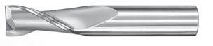
2 Flute Square End • 2 Flute Corner
2 Flute Square End • 2 Flute Corner Radius
TOLERANCES (inch) <1/8 DIAMETER
DC = +0.000 /–0.001
DCON = h 6 RE = +0.000 /–0.0005 ≥1/8 DIAMETER
DC = +0.000 /–0.002

5/8 2-1/2 1/4 30326 30483 – 3B 7/32 5/8 2-1/2 1/4 30328 30484 – 3B 15/64 3/4 2-1/2 1/4 30330 30485 – 3B *1/4 3/4 2-1/2 1/4 30332 30486 91279 3B 1/4 1-1/8
3B • 3LB •
(mm)
DCON = h 6
≥3 DIAMETER
DC = +0,0000 /–0.0508
DCON = h 6
RE = +0,0000 /–0.0508
2 Flute Ball End
TOLERANCES (inch)
<1/8 DIAMETER
DC = +0.000 /–0.001
DCON = h 6
≥1/8 DIAMETER
DC = +0.000 /–0.002
DCON = h 6
TOLERANCES (mm)
<3 DIAMETER
DC = +0,0000 /–0.0254
DCON = h 6
≥3 DIAMETER
DC = +0,0000 /–0.0508
DCON = h 6
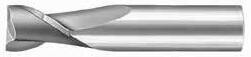
2 Flute High Shear
<1/8 DIAMETER
/–0.001
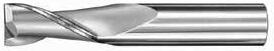
= h 6
≥1/8 DIAMETER
= +0.000 /–0.002 DCON = h 6
TOLERANCES (m m)
<3 DIAMETER
DC = +0,0000 /–0,0254 DCON = h 6
≥3 DIAMETER
TOLERANCES (inch)
1/8–1/4 DIAMETER
DC = +0.0000 /–0.0012
DCON = h 6
>1/4–3/8 DIAMETER
DC = +0.0000 /–0.0016
DCON = h 6
>3/8–3/4 DIAMETER
DC = +0.0000 /–0.0020
DCON = h 6
2 Flute Square End Long Reach

2 Flute Ball End Long Reach
1/8–1/4 DIAMETER

>1/4–3/8 DIAMETER
>3/8–3/4 DIAMETER
= +0.0000 /–0.0020
TOLERANCES (mm)
3–6 DIAMETER
DC = +0,0000 /–0,0254
DCON = h 6
>6–10 DIAMETER
DC = +0,0000 /–0,0406
DCON = h 6
>10–20 DIAMETER
DC = +0,0000 /–0,0508
DCON = h 6
2 Flute Square End Long Reach
2 Flute Ball End Long Reach
Option Available RE = 1/2 Cutting Diameter (DC)


<3 DIAMETER
DC
DCON = h 6
≥3 DIAMETER
DC
TOLERANCES (inch)


= h 6
= +0.000 /–0.002
4 Flute Square End • 4 Flute Corner Radius

4 Flute Square End • 4 Flute Corner Radius
TOLERANCES (inch)
<1/8 DIAMETER
≥1/8 DIAMETER DC = +0.000 /–0.002 DCON = h 6
= +0.000 /–0.002
4 Flute Square End • 4 Flute Corner Radius
4 Flute Square End • 4 Flute Corner Radius

TOLERANCES (mm)
<3 DIAMETER
DC = +0,0000 /–0,0254
DCON = h 6
≥3 DIAMETER
DC = +0,0000 /–0,0508
DCON = h 6
RE = +0,0000 /–0,0508
4 Flute Square End • 4 Flute Corner Radius

1,0
1,5
2,5
3,0 12,0 38,0 – 3,0 40121 48504 48526 48547 1M
3,0 25,0 75,0 – 3,0 43101 49388 49401 49414 1XLM
3,5 7,0 50,0 – 4,0 41625 49141
3,5
4,0
4,0 14,0 50,0 – 4,0 40129 48506 48528 48549 1M
4,0 14,0 50,0 0,25 4,0 – – – 40000 1MCR
4,0 14,0 50,0 0,50 4,0 – – – 40001 1MCR
4,0 14,0 50,0 0,76 4,0 – – – 40002 1MCR
4,0 14,0 50,0 1,00 4,0 – – – 40003 1MCR
4,0 25,0 75,0 – 4,0 43103 49389 49402 49415 1XLM
4,5 9,5 50,0 – 4,5 41633 49143 49164 49185 16M
4,5 16,0 50,0 – 6,0 40133 48507 48529 48550 1M
5,0 10,0 50,0 – 5,0 41637 49144 49165 49186 16M
5,0 16,0 50,0 – 6,0 40137 48508 48530 48551 1M
5,0 16,0 50,0 0,25 6,0 – – – 40004 1MCR
5,0
5,0 16,0
5,0
5,0
6,0
6,0
continued on next page
4 Flute Square End • 4 Flute Corner Radius
1M • 1XLM • 1MCR • 16M
TOLERANCES (mm)
<3 DIAMETER
DC = +0,0000 /–0,0254
DCON = h 6
≥3 DIAMETER
DC = +0,0000 /–0,0508
DCON = h 6
RE = +0,0000 /–0,0508
4 Flute Square End • 4 Flute Corner Radius
TOLERANCES (inch)
<1/8 DIAMETER
DC = +0.000 /–0.001
DCON = h 6
≥1/8 DIAMETER
DC
DCON = h 6
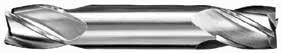
31178 11/64 5/16 2 3/16 31419 31459 39619 31179 *3/16 3/8 2 3/16 31421 31461 39621 31180 13/64 1/2 2-1/2 1/4 31423 31463 39623 31181
7/32
TOLERANCES (mm)
<3 DIAMETER
DC = +0,0000 /–0,0254
DCON = h 6
≥3 DIAMETER
DC = +0,0000 /–0,0508
DCON = h 6
4 Flute Double End Ball End

TOLERANCES (inch)
<1/8 DIAMETER
DC = +0.000 /–0.001
DCON = h 6
≥1/8 DIAMETER
DC = +0.000 /–0.002
DCON = h 6
TOLERANCES (mm)
<3 DIAMETER
DC = +0,0000 /–0,0254
DCON = h 6
≥3 DIAMETER
DC = +0,0000 /–0,0508
DCON = h 6
FRACTIONAL & METRIC
Single End Roughers (Coarse Pitch)
TOLERANCES (inch)
*Without Flat
RE = +0.0050/–0.0050
TOLERANCES (mm)
DC = +0,000 / –0,100
DCON = h 6
RE = +0,127/–0,127
Single End Roughers (Fine


Pictured: Series 1 4 Flute Single End Square Endmill Set
2 Flute: Square & Ball End
4 Flute: Square & Ball End
PLASTICS
Polycarbonate, PVC, Polypropylene
rpm = (Vc x 3.82) / DC
ipm = Fz x number of flutes x rpm finish cuts typically require reduced feed and cut depths (.02 x D maximum) refer to the KYOCERA SGS APEX for complete technical information (www.kyocera-sgstool.com/apex)
Series 1, 3, 5, 14, 16, 17, 23, 24, 59
Fractional
CARBON STEELS
1018, 1040, 1080, 1090, 10L50, 1140, 1212, 12L15, 1525, 1536
ALLOY STEELS
4140, 4150, 4320, 5120, 5150, 8630, 86L20, 50100
TOOL STEELS
STAINLESS STEELS (DIFFICULT)
304, 304L, 316, 316L, 17-4 PH, 15-5, 13-4, Custom 450
2 Flute: Square, Double, Stub, Long, Ball, Corner Radius
3 Flute: Square, Ball, Tapered
4 Flute: Square, Double, Stub, Ball, Corner Radius Tapered: Square, Radius
2 Flute: Square, Double, Stub, Long, Ball, Corner Radius
3 Flute: Square, Ball, Tapered
4 Flute: Square, Double, Stub, Ball, Corner Radius Tapered: Square, Radius
Series 1, 3, 5, 14, 16, 17, 23, 24, 59
Fractional
PLASTICS
Inconel 601, 617, 625, 718, Incoloy 800, Monel 400,Rene, Waspalloy
S HIGH TEMP ALLOYS (NICKEL, COBALT, IRON BASE)
TITANIUM ALLOYS
Ti6Al4V, Ti6Al2Sn4Zr2Mo, Ti4Al4Mo2Sn0.5Si, Ti10V2Fe3Al, Ti5Al53Mo3Cr, Ti7Al4Mo, Ti3Al8V6Cr4Zr4Mo, Ti6Al6V6Sn, Ti152 Cr3Sn3Al ≤ 350 Bhn or ≤ 38 HRc
Bhn (Brinell) HRc (Rockwell C) HRb (Rockwell B) rpm = (Vc x 3.82) / DC ipm = Fz x number of flutes x rpm reduce speed and feed for materials harder than listed for tapered end mills, base the speed on the largest diameter contacting the workpiece and the feed on the smallest diameter limit cut depths of long and extra long flute mills to .05 x DC when slotting or profiling reduce feed and Ae when finish milling (.02 x DC maximum) refer to the KYOCERA SGS APEX for complete technical information (www.kyocera-sgstool.com/apex)
ALUMINUM ALLOYS
2024, 5052, 5086, 6061, 6063, 7075
ALUMINUM DIE CAST ALLOYS (HIGH SILICON) A-390, A-392, B-390
PLASTICS
Polycarbonate, PVC, Polypropylene
Bhn (Brinell) HRc (Rockwell C) HRb (Rockwell B)
rpm = (Vc x 3.82) / DC
ipm = Fz x number of flutes x rpm reduce speed and feed for materials harder than listed reduce feed and Ae when finish milling (.02 x DC maximum) refer to the KYOCERA SGS APEX for complete technical information (www.kyocera-sgstool.com/apex)
2 Flute: High Shear 4 Flute: High Shear
Single End Roughers (Coarse Pitch)
CARBON STEELS
1018, 1040, 1080, 1090, 10L50, 1140, 1212, 12L15, 1525, 1536
ALLOY STEELS
4140, 4150, 4320, 5120, 5150, 8630, 86L20, 50100
7 HRc
28 HRc
TOOL STEELS
A2, D2, H13, L2, M2, P20, S7, T15, W2
K CAST IRONS Gray, Malleable, Ductile
250 Bhn or ≤ 24 HRc
≤ 220 Bhn or ≤ 19 HRc
Bhn (Brinell) HRc (Rockwell C)
rpm = (Vc x 3.82) / DC
ipm = Fz x number of flutes x rpm reduce speed and feed for materials harder than listed refer to the KYOCERA SGS APEX for complete technical information (www.kyocera-sgstool.com/apex)
303, 416, 420F, 430F, 440F
M STAINLESS STEELS (FREE MACHINING)
STAINLESS STEELS (DIFFICULT)
304, 304L, 316, 316L, 17-4PH, 15-5PH, 13-4PH, Custom 450
Single End Roughers (Fine Pitch)
Inconel 601, 617, 625, Incoloy 800, Monel 400, Rene, Waspalloy
S HIGH TEMP ALLOYS (NICKEL, COBALT, IRON BASE)
TITANIUM ALLOYS
Ti6Al4V, Ti6Al2Sn4Zr2Mo, Ti4Al4Mo2Sn0.5Si, Ti10V2Fe3Al, Ti5Al53Mo3Cr, Ti7Al4Mo, Ti3Al8V6Cr4Zr4Mo, Ti6Al6V6Sn, Ti152 Cr3Sn3Al
Bhn (Brinell) HRc (Rockwell C) rpm = (Vc x 3.82) / DC ipm = Fz x number of flutes x rpm reduce speed and feed for materials harder than listed refer to the KYOCERA SGS APEX for complete technical information (www.kyocera-sgstool.com/apex)
Series 1M, 3M, 5M, 14M, 16M, 17M, 59M
CARBON STEELS
1018, 1040, 1080, 1090, 10L50, 1140, 1212, 12L15, 1525, 1536
ALLOY STEELS
4140, 4150, 4320, 5120, 5150, 8630, 86L20, 50100
STAINLESS STEELS (DIFFICULT)
304, 304L, 316, 316L, 17-4 PH, 15-5, 13-4, Custom 450
K CAST IRONS
Series 1M, 3M, 5M, 14M, 16M, 17M, 59M
2 Flute: Square, Double, Stub, Long Reach, Ball 3 Flute: Square, Long Reach, Ball
4 Flute: Square, Double, Stub, Long Reach, Ball, Corner Radius
COPPER ALLOYS
Bronze, C110, Muntz Brass
PLASTICS
Polycarbonate, PVC, Polypropylene
GRAPHITE
(NICKEL, COBALT, IRON BASE)
Inconel 601, 617, 625, 718, Incoloy 800, Monel 400,Rene, Waspalloy
TITANIUM ALLOYS
Ti6Al4V, Ti6Al2Sn4Zr2Mo, Ti4Al4Mo2Sn0.5Si, Ti10V2Fe3Al, Ti5Al53Mo3Cr, Ti7Al4Mo, Ti3Al8V6Cr4Zr4Mo, Ti6Al6V6Sn, Ti152 Cr3Sn3Al
Bhn (Brinell) HRc (Rockwell C)
rpm = (Vc x 1000) / (DC x 3.14) mm/min = Fz x number of flutes x rpm reduce speed and feed for materials harder than listed
limit cut depths of long and extra long flute mills to .05 x DC when slotting or profiling reduce feed and Ae when finish milling (.02 x DC maximum) refer to the KYOCERA SGS APEX for complete technical information (www.kyocera-sgstool.com/apex))
2 Flute: High Shear
High
Shear
ALUMINUM ALLOYS
2024, 5052, 5086, 6061, 6063, 7075
ALUMINUM DIE CAST ALLOYS (HIGH SILICON) A-390, A-392, B-390
COPPER ALLOYS
Aluminum Bronze, Muntz Brass, Naval, Brass, Red Brass
COPPER ALLOYS
Beryllium Copper, C110, Manganese Bronze, Tin Bronze
Bhn (Brinell) HRc (Rockwell C) HRb (Rockwell B) rpm = (Vc x 1000) / (DC x 3.14) mm/min = Fz x number of flutes x rpm reduce speed and feed for materials harder than listed reduce feed and Ae when finish milling (.02 x DC maximum) refer to the KYOCERA SGS APEX for complete technical information (www.kyocera-sgstool.com/apex)
2 Flute: High Shear
4
Flute: High Shear
Single End Roughers (Coarse Pitch)
CARBON STEELS
1018, 1040, 1080, 1090, 10L50, 1140, 1212, 12L15, 1525, 1536
ALLOY STEELS
4140, 4150, 4320, 5120, 5150, 8630, 86L20, 50100
TOOL STEELS
A2, D2, H13, L2, M2, P20, S7, T15, W2
Bhn or
24 HRc
CAST IRONS Gray, Malleable, Ductile
220 Bhn or ≤ 19 HRc
Bhn (Brinell) HRc (Rockwell C)
rpm = (Vc x 1000) / (DC x 3.14)
mm/min = Fz x number of flutes x rpm reduce speed and feed for materials harder than listed refer to the KYOCERA SGS APEX for complete technical information (www.kyocera-sgstool.com/apex)
303, 416, 420F, 430F, 440F
M STAINLESS STEELS (FREE MACHINING)
STAINLESS STEELS (DIFFICULT)
304, 304L, 316, 316L, 17-4PH, 15-5PH, 13-4PH, Custom 450
Single End Roughers (Fine Pitch)
S
TEMP ALLOYS (NICKEL, COBALT, IRON BASE)
Inconel 601, 617, 625, Incoloy 800, Monel 400, Rene, Waspalloy
TITANIUM ALLOYS
Ti6Al4V, Ti6Al2Sn4Zr2Mo, Ti4Al4Mo2Sn0.5Si, Ti10V2Fe3Al, Ti5Al53Mo3Cr, Ti7Al4Mo, Ti3Al8V6Cr4Zr4Mo, Ti6Al6V6Sn, Ti152 Cr3Sn3Al
Bhn (Brinell) HRc (Rockwell C) rpm = (Vc x 1000) / (DC x 3.14) mm/min = Fz x number of flutes x rpm reduce speed and feed for materials harder than listed refer to the KYOCERA SGS APEX for complete technical information (www.kyocera-sgstool.com/apex)
VALUE AT THE SPINDLE
Solid Car bide Tools
General Application Drills

Hole Making
Taladrado
Outils de perçage
Recommandations

2 Flute Drills • Metric: DIN 338

0.0330 0,840 mm
Pictured:

continued on next page
2 Flute Drills • Metric: DIN 338
Pictured: Series 101 Drill Set
TOLERANCES (inch)
DC = +0.0000/–0.0005
TOLERANCES (mm)
DC = +0,0000/–0,0127
0.1875 4,760
0.1890 4,800
0.1890 4,800 mm #12
0.1929 4,900 mm
0.1935 4,910 mm #10 2-3/4
57158
0.1960 4,980 mm #9 3 1-3/4 1-13/32 51009 57159
0.1969 5,000 mm
0.2008 5,010 mm
5,110 mm #7 3
61023 68279
0.2031 5,160 mm 13/64 3 1-3/4 1-13/32 51113 57162
0.2040 5,180
• Metric: DIN 338
Pictured: Series
Short Length Self Centering Drills • DIN

TOLERANCES (mm)
≤3 DIAMETER
DC = +0,000/–0,010
DCON = h 6
>3–6 DIAMETER
DC = +0,000/–0,012
DCON = h 6
>6–10 DIAMETER
DC = +0,000/–0,015
DCON = h 6
>10–16 DIAMETER
DC = +0,000/–0,018
DCON = h 6
continued on next page
Short Length Self Centering Drills • DIN 6539
TOLERANCES (mm)
≤3 DIAMETER
>3–6 DIAMETER
>6–10 DIAMETER
= +0,000/–0,015
= h 6
>10–16 DIAMETER
DC = +0,000/–0,018 DCON = h 6
TOLERANCES (mm)
≤3 DIAMETER
DC = +0,000/–0,010
DCON = h 6
>3–6 DIAMETER
DC = +0,000/–0,012
DCON = h 6
>6–10 DIAMETER
DC = +0,000/–0,015
DCON = h 6
>10–16 DIAMETER
DC = +0,000/–0,018
DCON = h 6
Short Length Self Centering Drills • DIN
2 Flute Drills
CARBON STEELS
1018, 1040, 1080, 1090, 10L50, 1140, 1212, 12L15, 1525, 1536
TOOL STEELS
A2, D2, H13, L2, M2, P20, S7, T15, W2
STAINLESS STEELS (FREE MACHINING)
303, 416, 420F, 430F 440F
M
STAINLESS STEELS (DIFFICULT)
304, 316, 321, 13-8 PH, 15-5PH, 17-4 PH, Custom 450
K CAST IRONS Gray, Malleable, Ductile
ALUMINUM ALLOYS
2017, 2024, 356, 6061, 7075
COPPER ALLOYS
Bronze, C110, Muntz Brass
PLASTICS
HIGH TEMP ALLOYS (NICKEL,
Inconel 601, 617, 625, Incoloy 800, Monel 400, Rene, Waspaloy
TITANIUM ALLOYS (DIFFICULT)
Pure Titanium, Ti6Al4V, Ti6Al2Sn4Zr2Mo, Ti4Al4Mo2Sn0.5Si, Ti-6Al4V
H TOOL STEELS
A2, D2, H13, L2, M2, P20, S7, T15, W2
Bhn (Brinell) HRc (Rockwell C) HRb (Rockwell B)
rpm = Vc x 3.82 / DC
ipm = Fr x rpm reduce speed and feed 30 percent when using uncoated drills reduce speed and feed for materials harder than listed refer to the KYOCERA SGS APEX for complete technical information (www.kyocera-sgstool.com/apex)
2 Flute Drills
Short Length Self Centering Drills • DIN 6539
108M
CARBON STEELS
1018, 1040, 1080, 1090, 10L50, 1140, 1212, 12L15, 1525, 1536
ALLOY STEELS
4140, 4150, 4320, 5120, 5150, 8630, 86L20, 50100
TOOL STEELS
A2, D2, H13, L2, M2, P20, S7, T15, W2
STAINLESS STEELS (FREE MACHINING)
303, 416, 420F, 430F 440F
STAINLESS STEELS (DIFFICULT)
304, 316, 321, 13-8 PH, 15-5PH, 17-4 PH, Custom 450
K CAST IRONS Gray, Malleable, Ductile
ALUMINUM ALLOYS
2017, 2024, 356, 6061, 7075
Short Length Self Centering Drills • DIN
Bronze, C110, Muntz Brass
HIGH TEMP ALLOYS (NICKEL, COBALT, IRON BASE)
Inconel 601, 617, 625, Incoloy 800, Monel 400, Rene, Waspaloy
TITANIUM ALLOYS (DIFFICULT)
Pure Titanium, Ti6Al4V, Ti6Al2Sn4Zr2Mo, Ti4Al4Mo2Sn0.5Si, Ti-6Al4V
H TOOL STEELS
A2, D2, H13, L2, M2, P20, S7, T15, W2
Bhn (Brinell) HRc (Rockwell C) HRb (Rockwell B)
rpm = (Vc x 1000) / (DC x 3.14)
mm/min = Fr x rpm
reduce speed and feed 30 percent when using uncoated drills reduce speed and feed for materials harder than listed refer to the KYOCERA SGS APEX for complete technical information (www.kyocera-sgstool.com/apex)
Straight Flute Drills • Metric: DIN 6539

& METRIC SERIES
TOLERANCES (inch)
DC = +0.0000/–0.0005 DCON = h 6
TOLERANCES (mm)
DC = +0,0000/–0,0127
DCON = h 6
Straight Flute Drills • Metric: DIN
Straight Flute Drills • Metric: DIN 6539
& METRIC SERIES
P ALLOY STEELS
4140, 4150, 4320, 5120, 5150, 8630, 86L20, 50100
K CAST IRONS
H TOOL STEELS
Bhn (Brinell) HRc (Rockwell C)
rpm = Vc x 3.82 / DC
ipm = Fr x rpm
reduce speed and feed 30 percent when using uncoated drills refer to the KYOCERA SGS APEX for complete technical information (www.kyocera-sgstool.com/apex)
P ALLOY STEELS 4140, 4150, 4320, 5120, 5150, 8630, 86L20, 50100
K CAST IRONS Gray, Malleable, Ductile
TOOL
Bhn (Brinell) HRc (Rockwell C) rpm = (Vc x 1000) / (DC x 3.14) mm/min = Fr x rpm reduce speed and feed 30 percent when using uncoated drills refer to the KYOCERA SGS APEX for complete technical information (www.kyocera-sgstool.com/apex)
H
STEELS
D2, H13, L2, M2, P20, S7, T15, W2
3 Flute Drills • Metric: DIN 6539
0.1405
0.1496 3,800
0.1535 3,900 mm
0.1562 3,970 mm 5/32 2-1/2 1-3/8
0.1570
4,000
68975
3 Flute Drills • Metric: DIN
3 Flute Drills • Metric: DIN 6539
TOLERANCES (inch)
TOLERANCES (mm)
DC = +0,0000/–0,0127 DCON = h 6
0.3150 8,000
0.3160 8,030
0.3189 8,100 mm
0.3228 8,200
0.3268 8,300
0.3281 8,330 mm 21/64
53215 58075
63078 69018
2 53121 58077 0.3307 8,400 mm
0.3320 8,430
0.3390
63019 69019
3 Flute Drills • Metric: DIN 6539
3 Flute Drills
CARBON STEELS
1018, 1040, 1080, 1090, 10L50, 1140, 1212, 12L15, 1525, 1536
ALLOY STEELS
4140, 4150, 4320, 5120, 5150, 8630, 86L20, 50100
TOOL STEELS
A2, D2, H13, L2, M2, P20, S7, T15, W2
K CAST IRONS Gray, Malleable, Ductile
ALUMINUM ALLOYS
2017, 2024, 356, 6061, 7075
Bhn (Brinell) HRc (Rockwell C) HRb (Rockwell B)
rpm = Vc x 3.82 / DC
ipm = Fr x rpm
reduce speed and feed 30 percent when using uncoated drills reduce speed and feed for materials harder than listed refer to the KYOCERA SGS APEX for complete technical information (www.kyocera-sgstool.com/apex)
COPPER ALLOYS Alum Bronze, C110, Muntz Brass
H TOOL STEELS
A2, D2, H13, L2, M2, P20, S7, T15, W2
CARBON STEELS
1018, 1040, 1080, 1090, 10L50, 1140, 1212, 12L15, 1525, 1536
ALLOY STEELS
4140, 4150, 4320, 5120, 5150, 8630, 86L20, 50100
CAST IRONS Gray, Malleable, Ductile
ALUMINUM ALLOYS
2017, 2024, 356, 6061, 7075
COPPER ALLOYS
Alum Bronze, C110, Muntz Brass
H TOOL STEELS
A2, D2, H13, L2, M2, P20, S7, T15, W2
Bhn (Brinell) HRc (Rockwell C) HRb (Rockwell B)
rpm = (Vc x 1000) / (DC x 3.14)
mm/min = Fr x rpm
reduce speed and feed 30 percent when using uncoated drills reduce speed and feed for materials harder than listed refer to the KYOCERA SGS APEX for complete technical information (www.kyocera-sgstool.com/apex)
Combined Drill & Countersink

FRACTIONAL SERIES
Pictured: Series 301 Set
*00 .025 1/8 1-1/2 .312 57005 57015
*0 1/32 1/8 1-1/2 .312 57006 57016
*1 3/64 1/8 1-1/2 .375 57007 57017
*2 5/64 3/16 1-7/8 .562 57008 57018
*3 7/64 1/4 2 .625 57009 57019
*4 1/8 5/16 2-1/8 .750 57010 57020
*5 3/16 7/16 2-3/4 .875 57011 57021
*6 7/32 1/2 3 .938 57012 57022
TOLERANCES (mm)
DC = +0,076/–0,000
DCON = –0,0025/–0,0127
Combined Drill & Countersink
CARBON STEELS
1018, 1040, 1080, 1090, 10L50, 1140, 1212, 12L15, 1525, 1536
ALLOY STEELS
4140, 4150, 4320, 5120, 5150, 8630, 86L20, 50100
TOOL STEELS
A2, D2, H13, L2, M2, P20, S7, T15, W2
STAINLESS STEELS (FREE MACHINING)
303, 416, 420F, 430F 440F
STAINLESS STEELS (DIFFICULT)
304, 316, 321, 13-8 PH, 15-5PH, 17-4 PH, Custom 450
continued on next page
K CAST IRONS Gray, Malleable, Ductile
ALUMINUM ALLOYS
2017, 2024, 356, 6061, 7075
Inconel 601, 617, 625, Incoloy 800, Monel 400, Rene, Waspaloy
TITANIUM ALLOYS
Pure Titanium, Ti6Al4V, Ti6Al2Sn4Zr2Mo, Ti4Al4Mo2Sn0.5Si, Ti-6Al4V
H TOOL STEELS
A2, D2, H13, L2, M2, P20, S7, T15, W2
Bhn (Brinell) HRc (Rockwell C) HRb (Rockwell B) rpm = Vc x 3.82 / DCON ipm = Fr x rpm reduce speed and feed 30 percent when using uncoated drills reduce speed and feed for materials harder than listed refer to the KYOCERA SGS APEX for complete technical information (www.kyocera-sgstool.com/apex)
Combined Drill & Countersink
CARBON STEELS
1018, 1040, 1080, 1090, 10L50, 1140, 1212, 12L15, 1525, 1536
ALLOY STEELS
4140, 4150, 4320, 5120, 5150, 8630, 86L20, 50100
TOOL STEELS
A2, D2, H13, L2, M2, P20, S7, T15, W2
STAINLESS STEELS (FREE MACHINING)
303, 416, 420F, 430F 440F
STAINLESS STEELS (DIFFICULT)
304, 316, 321, 13-8 PH, 15-5PH, 17-4 PH, Custom 450
on next page
K CAST IRONS Gray, Malleable, Ductile
ALUMINUM ALLOYS
2017, 2024, 356, 6061, 7075
ALLOYS
Alum Bronze, C110, Muntz Brass
Inconel 601, 617, 625, Incoloy 800, Monel 400, Rene, Waspaloy
TITANIUM ALLOYS
Pure Titanium, Ti6Al4V, Ti6Al2Sn4Zr2Mo, Ti4Al4Mo2Sn0.5Si, Ti-6Al4V
H TOOL STEELS
A2, D2, H13, L2, M2, P20, S7, T15, W2
Bhn (Brinell) HRc (Rockwell C) HRb (Rockwell B) rpm = (Vc x 1000) / (DCON x 3.14) mm/min = Fr x rpm reduce speed and feed 30 percent when using uncoated drills reduce speed and feed for materials harder than listed refer to the KYOCERA SGS APEX for complete technical information (www.kyocera-sgstool.com/apex)
Single Flute Countersink

1/4 2 .125 – – 74207 1/4 1/4 2 .144 – 74107 –1/4 1/4 2 .217 74007 – –
*3/8 1/4 2-11/16 .188 – – 74210
*3/8 1/4 2-11/16 .216 – 74110 –*3/8 1/4 2-13/16 .325 74010
*1/2 1/4 2-3/4 .250 – – 74213
*1/2 1/4 2-3/4 .288 – 74113 –
*1/2 1/4 2-7/8 .433 74013 – –
*5/8 3/8 2-57/64 .313 – – 74216
*5/8 3/8 2-57/64 .360 – 74116 –
*5/8 3/8 3 .541 74016 – –
*3/4 1/2 2-57/64 .375 – – 74219
*3/4 1/2 2-57/64 .431 – 74119 –
*3/4 1/2 3 .650 74019 – –
*1 1/2 3 .500 – – 74222
*1 1/2 3 .575 – 74122 –
*1 1/2 3-1/4 .866 74022 – –
*Steel Shank / Con mango de acero / Avec queue en acier / Mit Stahlschaft
TOLERANCES (inch)
1/8–1/4 DIAMETER
DC = +0.0000/–0.0005
3/8–1 DIAMETER
DC = +0.003/–0.000
Included Angle +1°/–1°
STAINLESS STEELS CAST IRON NON-FERROUS HIGH TEMP ALLOYS HARDENED STEELS
CARBON STEELS
1018, 1040, 1080, 1090, 10L50, 1140, 1212, 12L15, 1525, 1536
ALLOY STEELS
TOOL STEELS A2, D2, H13, L2, M2, P20, S7, T15, W2
(DIFFICULT)
316, 321, 13-8 PH, 15-5PH, 17-4 PH, Custom 450
Single Flute Countersink
Single Flute Countersink
ALUMINUM ALLOYS
2017, 2024, 356, 6061, 7075
COPPER ALLOYS
Alum Bronze, C110, Muntz Brass
HIGH TEMP ALLOYS
(NICKEL, COBALT, IRON BASE)
Inconel 601, 617, 625, Incoloy 800, Monel 400, Rene, Waspaloy
TITANIUM ALLOYS
Pure Titanium, Ti6Al4V, Ti6Al2Sn4Zr2Mo, Ti4Al4Mo2Sn0.5Si, Ti-6Al4V
H TOOL STEELS
A2, D2, H13, L2, M2, P20, S7, T15, W2
Bhn (Brinell) HRc (Rockwell C) HRb (Rockwell B)
rpm = Vc x 3.82 / DC
ipm = Fr x rpm
reduce speed and feed for materials harder than listed refer to the KYOCERA SGS APEX for complete technical information (www.kyocera-sgstool.com/apex)
DC2
TOLERANCES (inch)
1/8–1/4 DIAMETER
DC = +0.0000/–0.0005
3/8–1 DIAMETER
DC = +0.003/–0.000 Included Angle +1°/–1°

*3/8 1/4 2-11/16 .165 .088 – 74134 –*3/8 1/4 2-13/16 .255 .080 74034 – –
*1/2 1/4 2-3/4 .199 .102 – – 74237
*1/2 1/4 2-3/4 .229 .102 – 74137 –
*1/2 1/4 2-7/8 .352 .093 74037 – –
*5/8 3/8 2-57/64 .254 .118 – – 74240
*5/8 3/8 2-57/64 .292 .118 – 74140 –
*5/8 3/8 3
1/2 3 .426 .148 – – 74246
*1 1/2 3 .490 .148 – 74146 –*1 1/2 3-1/4 .747 .138 74046 – –
*Steel Shank / Con mango de acero / Avec queue en acier / Mit Stahlschaft NOTE: DC1 dimension varies based on angle. Contact your KSPT representative or consult KYOCERA SGS APEX for dimension information.
3 Flute Countersink
CARBON STEELS
1018, 1040, 1080, 1090, 10L50, 1140, 1212, 12L15, 1525, 1536
ALLOY STEELS
4140, 4150, 4320, 5120, 5150, 8630, 86L20, 50100
TOOL STEELS
A2, D2, H13, L2, M2, P20, S7, T15, W2
STAINLESS STEELS (FREE MACHINING)
303, 416, 420F, 430F 440F
STAINLESS STEELS (DIFFICULT)
304, 316, 321, 13-8 PH, 15-5PH, 17-4 PH, Custom 450
continued on next page
K CAST IRONS Gray, Malleable, Ductile
ALUMINUM ALLOYS
2017, 2024, 356, 6061, 7075
COPPER ALLOYS
Alum Bronze, C110, Muntz Brass
Inconel 601, 617, 625, Incoloy 800, Monel 400, Rene, Waspaloy
TITANIUM ALLOYS
Pure
H TOOL STEELS
A2, D2, H13, L2, M2, P20, S7, T15, W2
Bhn (Brinell) HRc (Rockwell C) HRb (Rockwell B)
rpm = Vc x 3.82 / DC
ipm = Fr x rpm
reduce speed and feed for materials harder than listed refer to the KYOCERA SGS APEX for complete technical information (www.kyocera-sgstool.com/apex)
3 Flute Countersink
1/8 1/8 1-1/2 .050 .025 – – 74249
1/8 1/8 1-1/2 .058 .025 – 74149 –1/8 1/8 1-1/2 .087 .025 74049 – –
3/16 3/16 2 .076 .035 – – 74252
3/16 3/16 2 .088 .035 – 74152 –3/16 3/16 2 .132 .035 74052 – –
1/4 1/4 2 .100 .050 – – 74255 1/4 1/4 2 .115 .050 – 74155 –1/4 1/4 2 .173 .050 74055 – –
*3/8 1/4 2-11/16 .148 .080 – – 74258
*3/8 1/4 2-11/16 .170 .080 – 74158 –
*3/8 1/4 2-13/16 .255 .080 74058 – –
*1/2 1/4 2-3/4 .180 .140 – – 74261
*1/2 1/4 2-3/4 .207 .140 – 74161 –
*1/2 1/4 2-7/8 .312 .140 74061 – –
*5/8 3/8 2-57/64 .228 .170 – – 74264
*5/8 3/8 2-57/64 .262 .170 – 74164 –
*5/8 3/8 3 .394 .170 74064 – –
*3/4 1/2 2-57/64 .275 .200 – – 74267
*3/4 1/2 2-57/64 .316 .200 – 74167 –
*3/4 1/2 3 .476 .200 74067 – –
*1 1/2 3 .380 .240 – – 74270
*1 1/2 3 .437 .240 – 74170 –
*1 1/2 3-1/4 .658 .240 74070 – –
*Steel Shank / Con mango de acero / Avec queue en acier / Mit Stahlschaft
NOTE: DC1 dimension varies based on angle. Contact your KSPT representative or consult KYOCERA SGS APEX for dimension information.
TOLERANCES (inch)
1/8–1/4 DIAMETER
DC = +0.0000/–0.0005
3/8–1 DIAMETER
DC = +0.003/–0.000
Included Angle +1°/–1°
TEMP ALLOYS HARDENED STEELS
CARBON STEELS
1018, 1040, 1080, 1090, 10L50, 1140, 1212, 12L15, 1525, 1536
ALLOY STEELS
4140, 4150, 4320, 5120, 5150, 8630, 86L20, 50100
TOOL STEELS
A2, D2, H13, L2, M2, P20, S7, T15, W2
STAINLESS STEELS (DIFFICULT)
304, 316, 321, 13-8 PH, 15-5PH, 17-4 PH, Custom 450
6 Flute Countersink
K CAST IRONS Gray, Malleable, Ductile
ALUMINUM ALLOYS
2017, 2024, 356, 6061, 7075
continued on next page
COPPER ALLOYS
Alum Bronze, C110, Muntz Brass
HIGH TEMP ALLOYS (NICKEL, COBALT, IRON BASE)
Inconel 601, 617, 625, Incoloy 800, Monel 400, Rene, Waspaloy
S
TITANIUM ALLOYS Pure
Ti6Al4V, Ti6Al2Sn4Zr2Mo, Ti4Al4Mo2Sn0.5Si, Ti-6Al4V
H TOOL STEELS
A2, D2, H13, L2, M2, P20, S7, T15, W2
Bhn (Brinell) HRc (Rockwell C) HRb (Rockwell B)
rpm = Vc x 3.82 / DC
ipm = Fr x rpm
reduce speed and feed for materials harder than listed refer to the KYOCERA SGS APEX for complete technical information (www.kyocera-sgstool.com/apex)
Straight Flute Accu-Reamer
SER 200 Metric reamers can be ordered to specific diameters according to the size range of Cutting Diameter DC. Please order as:
• 200. Then the size of the cut diameter in decimal format.
• i.e. 200.0492
• Description: Series 200 size 0.0492
• For Metric sizes convert to decimal inches (i.e. ÷ 25.4)
• The above sample would be a 1.25mm size (1.25 ÷ 25.4 = 0.0492") All other dimensions are fractional as per table including the Shank
Straight Flute Accu-Reamer
P
CARBON STEELS
1018, 1040, 1080, 1090, 10L50, 1140, 1212, 12L15, 1525, 1536
STEELS
4140, 4150, 4320, 5120, 5150, 8630, 86L20, 50100
TOOL STEELS
A2, D2, H13, L2, M2, P20, S7, T15, W2
STAINLESS STEELS (FREE MACHINING)
303, 416, 420F, 430F 440F
STAINLESS STEELS (DIFFICULT)
304, 316, 321, 13-8 PH, 15-5PH, 17-4 PH, Custom 450
K CAST IRONS Gray, Malleable, Ductile
Straight Flute Accu-Reamer
ALUMINUM ALLOYS
2017, 2024, 356, 6061, 7075
COPPER ALLOYS
Alum Bronze, C110, Muntz Brass
Inconel 601, 617, 625, Incoloy 800, Monel 400, Rene, Waspaloy
TITANIUM ALLOYS
Pure Titanium, Ti6Al4V, Ti6Al2Sn4Zr2Mo, Ti4Al4Mo2Sn0.5Si, Ti-6Al4V
H TOOL STEELS
A2, D2, H13, L2, M2, P20,
Bhn (Brinell) HRc (Rockwell C) HRb (Rockwell B)
rpm = Vc x 3.82 / DC
ipm = Fr x rpm
increase speed and feed 30 percent when using coated reamers reduce speed and feed for materials harder than listed refer to the KYOCERA SGS APEX for complete technical information (www.kyocera-sgstool.com/apex)
S7, T15, W2
Straight Flute Reamer
TOLERANCES (mm)
1–6 DIAMETER
DIAMETER
= +0,010/–0,000
CARBON STEELS
1018, 1040, 1080, 1090, 10L50, 1140, 1212, 12L15, 1525, 1536
ALLOY STEELS
4140, 4150, 4320, 5120, 5150, 8630, 86L20, 50100
TOOL STEELS
A2, D2, H13, L2, M2, P20, S7, T15, W2
STAINLESS STEELS (DIFFICULT)
304, 316, 321, 13-8 PH, 15-5PH, 17-4 PH, Custom 450
Straight Flute Reamer
Straight Flute Reamer
K CAST IRONS Gray, Malleable, Ductile
ALUMINUM ALLOYS
2017, 2024, 356, 6061, 7075
COPPER ALLOYS
Alum Bronze, C110, Muntz Brass
continued on next page
Straight Flute Reamer
HIGH TEMP ALLOYS
(NICKEL, COBALT, IRON BASE)
Inconel 601, 617, 625, Incoloy 800, Monel 400, Rene, Waspaloy
S
TITANIUM ALLOYS
Pure Titanium, Ti6Al4V, Ti6Al2Sn4Zr2Mo, Ti4Al4Mo2Sn0.5Si, Ti-6Al4V
H TOOL STEELS
A2, D2, H13, L2, M2, P20, S7, T15, W2
Bhn (Brinell) HRc (Rockwell C) HRb (Rockwell B) rpm = (Vc x 1000) / (DC x 3.14) mm/min = Fr x rpm increase speed and feed 30 percent when using coated reamers reduce speed and feed for materials harder than listed refer to the KYOCERA SGS APEX for complete technical information (www.kyocera-sgstool.com/apex)
VALUE AT THE SPINDLE
Solid
Car bide Tools
Routers

Speed & Feed Recommendations listed after each series
Ranurado
Recomendaciones de velocidades y avances mostradas tras cada serie
Détourage
Recommandations de vitesse et avance indiquées après chaque série
für Drehzahl & Vorschub im Anhang zu jeder Serie
Carbon Composite
20-CCR
FRACTIONAL SERIES
• Multi-flute design and positive geometry to shear with minimal pressure and delamination
• Unique clearance grind minimizes contact between tool diameter and workpiece eliminating friction
• Left hand flutes engineered to control the fibers within CFRP, preventing excessive fiber breakout
• Excels at trimming and profiling
abrasive fiber filled plastics
20M-CCR METRIC SERIES
• Multi-flute design and positive geometry to shear with minimal pressure and delamination
• Unique clearance grind minimizes contact between tool diameter and workpiece eliminating friction
• Left hand flutes engineered to control the fibers within CFRP, preventing excessive fiber breakout
• Excels at trimming and profiling difficult and abrasive fiber filled plastics
= h 6

• Multi-flute design and positive geometry to shear with minimal pressure and delamination
• Unique clearance grind minimizes contact between tool diameter and workpiece eliminating friction
• Left hand flutes engineered to control the fibers within CFRP, preventing excessive fiber breakout
• Excels at trimming and profiling difficult and abrasive fiber filled plastics
• Multi-flute design and positive geometry to shear with minimal pressure and delamination
• Unique clearance grind minimizes contact between tool diameter and workpiece eliminating friction
• Left hand flutes engineered to control the fibers within CFRP, preventing excessive fiber breakout
• Excels at trimming and profiling difficult and abrasive fiber filled plastics TOLERANCES (inch) DC = +.000/–.005
Carbon Composite
HSM (high speed machining)
finish cuts typically required reduced feed and cutting depths rpm = Vc x 3.82 / DC rates shown are for use without coolant; rates may be increased with coolant ipm = Fr x rpm dust collection is vital when machining dry adjust parameters based on resin type and fiber structure diamond coating will increase tool life in graphite and composite materials reduce speed when overheating causes melting or damage to resin refer to the KYOCERA SGS APEX for complete technical information reduce feed if delamination or fraying occur (www.kyocera-sgstool.com/apex)
HSM (high speed machining) finish cuts typically required reduced feed and cutting depths rpm = (Vc x 1000) / (DC x 3.14) rates shown are for use without coolant; rates may be increased with coolant mm/min = Fr x rpm dust collection is vital when machining dry adjust parameters based on resin type and fiber structure diamond coating will increase tool life in graphite and composite materials reduce speed when overheating causes melting or damage to resin refer to the KYOCERA SGS APEX for complete technical information reduce feed if delamination or fraying occur (www.kyocera-sgstool.com/apex)
Coarse Cut Carbon Composite
31-CCR FRACTIONAL SERIES
• Fewer, deeper flutes to prevent clogging in heavy routing
• Unique clearance grind minimizes contact between tool diameter and workpiece eliminating friction
• Left hand flutes engineered to control the fibers within CFRP, preventing excessive fiber breakout
• Excels at trimming and profiling difficult and abrasive fiber filled plastics
(mm)
= h 6
Coarse Cut Carbon Composite
PLASTICS
HSM (high speed machining) finish cuts typically required reduced feed and cutting depths rpm = Vc x 3.82 / DC rates shown are for use without coolant; rates may be increased with coolant ipm = Fr x rpm dust collection is vital when machining dry adjust parameters based on resin type and fiber structure diamond coating will increase tool life in graphite and composite materials reduce speed when overheating causes melting or damage to resin refer to the KYOCERA SGS APEX for complete technical information reduce feed if delamination or fraying occur (www.kyocera-sgstool.com/apex)
Coarse Cut Carbon Composite
HSM (high speed machining)
finish cuts typically required reduced feed and cutting depths rpm = (Vc x 1000) / (DC x 3.14) rates shown are for use without coolant; rates may be increased with coolant mm/min = Fr x rpm dust collection is vital when machining dry adjust parameters based on resin type and fiber structure diamond coating will increase tool life in graphite and composite materials reduce speed when overheating causes melting or damage to resin refer to the KYOCERA SGS APEX for complete technical information reduce feed if delamination or fraying occur (www.kyocera-sgstool.com/apex)


TOLERANCES (inch)
DC = +.000/–.003
DCON = h 6
• Compression-style helixes direct cutting forces inward, eliminating fiber breakout and delamination
• Primary/secondary relief grind for reduced friction and pressure
• Rigid, heavy core
TOLERANCES (mm)
DC = +0,000/–0,080
DCON = h 6
• Compression-style helixes direct cutting forces inward, eliminating fiber breakout and delamination
• Primary/secondary relief grind for reduced friction and pressure
• Rigid, heavy core
AFRP (CARBON FIBER, ARAMID FIBER)
GFRP (FIBERGLASS)
CARBON, GRAPHITE
HSM (high speed machining)
finish cuts typically required reduced feed and cutting depths rpm = Vc x 3.82 / DC rates shown are for use without coolant; rates may be increased with coolant ipm = Fz x number of flutes x rpm dust collection is vital when machining dry adjust parameters based on resin type and fiber structure diamond coating will increase tool life in graphite and composite materials reduce speed when overheating causes melting or damage to resin refer to the KYOCERA SGS APEX for complete technical information reduce feed if delamination or fraying occur (www.kyocera-sgstool.com/apex)
AFRP (CARBON FIBER, ARAMID FIBER)
CARBON, GRAPHITE
HSM (high speed machining)
finish cuts typically required reduced feed and cutting depths rpm = (Vc x 1000) / (DC x 3.14) rates shown are for use without coolant; rates may be increased with coolant mm/min = Fz x number of flutes x rpm dust collection is vital when machining dry adjust parameters based on resin type and fiber structure diamond coating will increase tool life in graphite and composite materials reduce speed when overheating causes melting or damage to resin refer to the KYOCERA SGS APEX for complete technical information reduce feed if delamination or fraying occur (www.kyocera-sgstool.com/apex)

TOLERANCES (mm)

TOLERANCES (inch)
DC = +.000/–.003 DCON = h 6
TOLERANCES (mm)
DC = +0,000/–0,080 DCON = h 6
NON-FERROUS
Up Cut Down Cut
N PLASTICS
rpm = (Vc x 1000) / (DC x 3.14) mm/min = Fz x 2 x rpm
EDP Number Index
EDP Number Index
EDP Number Index
EDP Number Index
EDP Number Index
EDP Number Index
EDP Number Index
EDP Number Index
EDP Number Index
EDP Number Index
EDP Number Index
EDP Number Index
EDP Number Index
66421 196
197 66436 197
66437 197
66438............ 197
66439 197 66440 197 66441............ 197 66442 197 66443 197 66444 197 66445............ 197 66446 197 66447 197 66448 197 66449 197 66450 197 66451 197 66452............ 197 66453 197 66454 197 66455 197 66456............ 197
197 66458 197 66459 197 66460 197 66461 197 66462 197 66463............ 197 66464 197 66465 197 66466 197 66467............ 197 66468 197 66469 197 66470............ 197 66471 197 66472 197 66473 197 66474............ 198 66475 198 66476 198 66477 198 66478 198 66479 198
EDP Number Index
EDP Number Index
EDP Number Index
95 81001............ 382
81003 382
81005 382
81007 382 81009 382 81011 382 81013 382 81015............ 382
95
95
95
95
81017 382 81019 382 81021 382 81023 382 81025 382
81027 382 81029............ 382
82930 390 82931 390 82932 390 82933............ 390
82966 390 82967 390
82968 390 82969 390 82970............ 390 82971 390 82972 390 82973 390 82974 394
82975 394
82976 394
82977............ 394 82978 394
82979 394
82980 394
82981............ 394
82982 394 82983 394 82984............ 394
82985 394
82986 394
82987 394 82988............ 394 82989 394
82990 397
82991 397
82992 397
82993 397
82994 397
82995............ 397 82996 397
82997 397 83026 390 83027............ 390 83028 390 83029 390 83041 390 83042 390 83043 390 83044 390 83056............ 127 83057 127 83058 127 83059 127 83060............ 127 83061 127 83062 127 83063............ 127 83064 127 83065 127
sfm = rpm x .262 x cutting diameter
rpm = sfm x 3.82 / cutting diameter
feed (inches per tooth) = ipm / ( number of teeth x rpm)
KSPT Reference Information
MACHINING FORMULAS
feed (inches / minute) = inches per tooth x number of teeth x rpm
feed (inches / minute) = ipr x rpm
feed (inches / revolution) = ipm / rpm
cusp height = (tool diameter / 2) – √(tool diameter2 – pitch2) / 4
pitch = √4 x (cusp height x tool diameter) – 4 x (cusp height2)
m/min = (3.14 x cutting diameter x rpm) / 1000
rpm = (1000 x m / min) / (3.14 x cutting diameter)
feed (mm per tooth) = millimeters per minute / (number of teeth x rpm)
feed (mm/minute) = feed per tooth x number of teeth x rpm
feed (mm/minute) = mmr x rpm
feed (mm per revolution) = mmr / rpm
cusp height = (tool diameter / 2) –√ (tool diameter2 – pitch2) / 4
pitch = √4 x (cusp height x tool diameter) – 4 x (cusp height2)
mrr – milling – (in3/min) = width of cut x depth of cut x ipm mrr – milling – (cm3/min) = (width of cut x depth of cut x mm/min) / 1000
cutting time – drilling – (minutes) = length / ipm
cutting time – drilling – (minutes) = length / mm/min
sfm surface feet per minute
rpm revolutions per minute
ipm feed rate in inches per minutes
ipr inches per revolution
mmr
millimeters per revolution
mm/min feed rate in millimeters per minute
mrr
material removal rate on flat surface
GENERAL FORMULAS
coolant pressure: 1 Bar = 14.5 Pounds per Square Inch (PSI)
calculation of coolant pressure: Pounds Per Square Inch (PSI) = (Horsepower of Pump x 1.460) / Gallons per Minute (GPM)
1 Liter = 0.254 Gallons
inch = millimeters / 25.4 millimeters = inch x 25.4
inch tap drill sizes = major diameter – ((1.299 x % of thread) / threads per inch)
metric tap drill sizes = major diameter – (1.082 x pitch x % of thread)
inch thread forming drill size: maximum diameter = basic major diameter – (3/8 x number of threads per inch)
inch thread forming drill size: minimum diameter = basic major diameter – (1/2 x number of threads per inch)
metric thread forming drill size: maximum diameter = basic major diameter – (.375 x pitch)
metric thread forming drill size: minimum
(.500 x pitch)
Decimal Equivalents
INCH METRIC DECIMAL EQUIVALENT
1,60 0.0630 #52 1,61 0.0635
1,65 0.0650 #51 1,70 0.0669
1,75 0.0689 #50 1,78 0.0700
1,80 0.0709
#49 1,85 0.0728
1,90 0.0748
#48 1,93 0.0760
1,95 0.0768
5/64 1,98 0.0781
#47 1,99 0.0785
2,00 0.0787
2,05 0.0807
#46 2,06 0.0810
#45 2,08 0.0820
2,10 0.0827
2,15 0.0846 #44 2,18 0.0860
2,20 0.0866
2,25 0.0886 #43 2,26 0.0890 – 2,30 0.0906 – 2,35 0.0925 #42 2,37 0.0935 3/32 2,38 0.0938
2,40 0.0945
#41 2,44 0.0960 – 2,45 0.0965
#40 2,50 0.0984 #39 2,53 0.0995 #38 2,58 0.1015
2,60 0.1024 #37 2,64 0.1040
2,70 0.1063
#36 2,71 0.1065
– 2,75 0.1083
7/64 2,78 0.1094 #35 2,79 0.1100
2,80 0.1102
#34 2,82 0.1110
#33 2,87 0.1130
2,90 0.1142 #32 2,95 0.1160
– 3,00 0.1181
#31 3,05 0.1200 – 3,10 0.1220
1/8 3,18 0.1250
9/64 3,57 0.1406
– 3,60 0.1417
#27 3,66 0.1440
3,70 0.1457 #26 3,73 0.1470
3,75 0.1476
#25 3,80 0.1495
– 3,80 0.1496
#24 3,86 0.1520
– 3,90 0.1535
#23 3,91 0.1540
5/32 3,97 0.1562
#22 3,99 0.1570 – 4,00 0.1575
#21 4,04 0.1590
#20 4,09 0.1610 – 4,10 0.1614
– 4,20 0.1654
#19 4,22 0.1660
4,25 0.1673
4,30 0.1693
#18 4,31 0.1695
11/64 4,37 0.1719
#17 4,39 0.1730 – 4,40 0.1732
#16 4,50 0.1770 – 4,50 0.1772
#15 4,57 0.1800
– 4,60 0.1811
#14 4,62 0.1820
#13 4,70 0.1850
– 4,75 0.1870
3/16 4,76 0.1875
#12 4,80 0.1890
#11 4,85 0.1910
– 4,90 0.1929
#10 4,91 0.1935
#9 4,98 0.1960
– 5,00 0.1969
#8 5,05 0.1990 – 5,10 0.2008
#7 5,11 0.2010
13/64 5,16 0.2031
#6 5,18 0.2040
– 5,20 0.2047
#5 5,22 0.2055
– 5,25 0.2067
– 5,3 0.2087
#1 5,79 0.2280
– 5,80 0.2283
– 5,90 0.2323
A 5,94 0.2340
15/64 5,95 0.2344 – 6,00 0.2362
B 6,05 0.2380
– 6,10 0.2402
C 6,15 0.2420
– 6,20 0.2441
D 6,25 0.2461
6,30 0.2480
E 6,35 0.2500 1/4 6,35 0.2500
– 6,40 0.2520 – 6,50 0.2559
F 6,53 0.2570
– 6,60 0.2598
G 6,63 0.2610
6,70 0.2638 17/64 6,75 0.2656
H 6,76 0.2660 – 6,80 0.2677 – 6,90 0.2717
I 6,91 0.2720
7,00 0.2756
J 7,04 0.2770
7,10 0.2795
K 7,14 0.2810
9/32 7,14 0.2812
– 7,20 0.2835
– 7,25 0.2854
– 7,30 0.2874
L 7,37 0.2900
7,40 0.2913
M 7,49 0.2950
7,50 0.2953
19/64 7,54 0.2969 – 7,60 0.2992
N 7,67 0.3020
7,70 0.3031
7,75 0.3051
7,80 0.3071
7,90 0.3110
5/16 7,94 0.3125 – 8,00 0.3150 O 8,03 0.3160 – 8,10 0.3189
INCH METRIC DECIMAL EQUIVALENT R 8,61 0.3390
– 8,70 0.3425
11/32 8,73 0.3438 – 8,75 0.3445 – 8,80 0.3465
S 8,84 0.3480
8,90 0.3504
– 9,00 0.3543
T 9,09 0.3580 – 9,10 0.3583 23/64 9,13 0.3594
9,20 0.3622
9,25 0.3642
9,30 0.3661 U 9,35 0.3680 – 9,40 0.3701
– 9,50 0.3740
3/8 9,53 0.3750
V 9,56 0.3770
9,60 0.3780
9,70 0.3819
9,75 0.3839
W 9,80 0.3858
– 9,90 0.3898 25/64 9,92 0.3906 – 10,00 0.3937
X 10,08 0.3970 – 10,10 0.3976
10,20 0.4016 Y 10,26 0.4040 – 10,30 0.4055
13/32 10,32 0.4062
– 10,40 0.4094
Z 10,49 0.4130
10,50 0.4134
10,60 0.4173
10,70 0.4213
27/64 10,72 0.4219 – 10,80 0.4252 – 10,90 0.4291
11,00 0.4331
11,10 0.4370
7/16 11,11 0.4375
11,20 0.4409 – 11,30 0.4449 – 11,40 0.4488 – 11,50 0.4528
29/64 11,51 0.4531
1,25 0.0492
1,30
3,20 0.1260
3,25 0.1280 #30 3,26 0.1285
– 3,30 0.1299 – 3,40 0.1339 #29 3,45 0.1360
3,50 0.1378
#28 3,57 0.1405
#4 5,31 0.2090 – 5,40 0.2126
#3 5,41 0.2130
– 5,50 0.2165
7/32 5,56 0.2188
– 5,60 0.2205
#2 5,61 0.2210 – 5,70 0.2244 – 5,75 0.2264
8,20 0.3228 P 8,20 0.3230
8,25 0.3248 – 8,30 0.3268 21/64 8,33 0.3281
8,40 0.3307 Q 8,43 0.3320
8,50 0.3346
8,60 0.3386
11,60 0.4567
11,70 0.4606
11,80 0.4646 – 11,90 0.4685 15/32 11,91 0.4688
12,00 0.4724 31/64 12,30 0.4844
12,50 0.4921 1/2 12,70 0.5000
Hardness Conversion Chart
KYOCERA SGS Precision Tools, Inc. 150 Marc Drive Cuyahoga Falls, Ohio 44223 U.S.A. (330) 686-5700
sales@kyocera-sgstool.com www.kyocera-sgstool.com KYOCERA SGS Precision Tools Europe, Ltd. 10 Ashville Way Wokingham, Berkshire RG41 2PL England (44) 1189-795-200
saleseu@kyocera-sgstool.com www.kyocera-sgstool.co.uk