TECHNICAL MANUAL Litho in U.S.A John Deere Lawn & Grounds Care Division TRS21/21E/22/24/26/27/32 and TRX24/26 Walk-Behind Snowthrowers/Snowblowers TM1466 (20Jan95) Replaces TM1466 (25Aug92)
FOREWORD
This manual is written for an experienced technician. Essential tools required in performing certain service work are identified in this manual and are recommended for use.
Live with safety: Read the safety messages in the introduction of this manual and the cautions presented throughout the text of the manual.
NThis is the safety-alert symbol. When you see this symbol on the machine or in this manual, be alert to the potential for personal injury.
Technical manuals are divided in two parts: repair and diagnostics. Repair sections tell how to repair the components. Diagnostic sections help you identify the majority of routine failures quickly.
Information is organized in groups for the various components requiring service instruction. At the beginning of each group are summary listings of all applicable essential tools, other materials needed to do the job and service parts kits.
Section 10, Group 15—Repair Specifications, consist of all applicable specifications, near tolerances and specific torque values for various components on each individual machine.
Binders, binder labels, and tab sets can be ordered by John Deere dealers direct from the John Deere Distribution Service Center.
This manual is part of a total product support program.
FOS MANUALS—REFERENCE
TECHNICAL MANUALS—MACHINE SERVICE
COMPONENT MANUALS—COMPONENT SERVICE
Fundamentals of Service (FOS) Manuals cover basic theory of operation, fundamentals of troubleshooting, general maintenance, and basic type of failures and their causes. FOS Manuals are for training new personnel and for reference by experienced technicians.
Technical Manuals are concise guides for specific machines. Technical manuals are on-the-job guides containing only the vital information needed for diagnosis, analysis, testing, and repair.
Component Technical Manuals are concise service guides for specific components. Component technical manuals are written as stand-alone manuals covering multiple machine applications.
MX,TMIFC,A -19-18OCT91 Introduction TM1466 (25AUG92) TRS/TRX Series Snowblowers 270995
Contents
SECTION 10—GENERAL INFORMATION
Group 05—Safety
Group 10—General Specifications
Group 15—Repair Specifications
Group 20—Fuels and Lubricants
Group 25—Serial Number Locations
SECTION 20—4 AND 5-HP ENGINE REPAIR—TRS22 AND TRS/TRX24
Group 05—Carburetor, Fuel Tank, and Muffler
Group 10—Remove and Install Engine
Group 15—Blower Housing, Cylinder Head, and Breather
Group 20—Governor, Camshaft, and Tappets
Group 25—Flywheel, Crankshaft and Piston Assembly
Group 30—Cylinder Block
Group 35—Recoil Starter
SECTION 21—8 AND 10-HP ENGINE REPAIR—TRS/TRX26, TRS27, TRS32
Group 05—Carburetor, Fuel Tank, and Muffler
Group 10—Remove and Install Engine
Group 15—Blower Housing, Cylinder Head, and Breather
Group 20—Governor, Camshaft, and Tappets
Group 25—Flywheel, Crankshaft and Piston Assembly
Group 30—Cylinder Block
Group 35—Recoil Starter
SECTION 25—4 AND 5-HP ENGINE REPAIR—TRS21
Group 05—Fuel System and Muffler
Group 10—Engine
Group 15—Recoil Starter
SECTION 40—ELECTRICAL
Group 05—Electric Starter—4-Cycle Engines
Group 06—Electric Starter
Group 10—4 and 5-HP Ignition and Charging
System
Group 15—8 and 10-HP Ignition and Charging System
Group 20—4 HP (2-Cycle) Ignition System
SECTION 50—POWER TRAIN—TRS22, TRS/TRX24 & 26
Group 05—Drive Belt Care and Maintenance
Group 10—Power Train Repair
Group 15—Blower and Auger Drive Repair
SECTION 55—POWER TRAIN—TRS27 AND 32
Group 05—Drive Belt Care and Maintenance
Group 10—Power Train Repair—TRS27 and 32 (S.N. —140000)
Group 15—Blower and Auger Drive Repair
Group 20—Power Train Repair—TRS27 and 32 (S.N. 140001— )
SECTION 85—AUGER DRIVE SYSTEM—TRS21
Group 05—Drive Belt Care and Maintenance
Group 10—Auger Drive Repair
SECTION 210—TEST AND ADJUSTMENT SPECIFICATIONS/OPERATIONAL CHECKOUT PROCEDURES
Group 05—Test and Adjustment Specifications
Group 10—Operational Checkout Procedures
SECTION 220—ENGINE—4-CYCLE ENGINES
Group 05—Component Location
Group 10—Theory of Operation
Group 15—Diagnosis, Tests and Adjustments
SECTION 225—ENGINE—2-CYCLE ENGINES
Group 05—Component Location
Group 10—Theory of Operation
Group 15—Diagnosis, Tests and Adjustments
Continued on next page
All information, illustrations and specifications in this manual are based on the latest information available at the time of publication. The right is reserved to make changes at any time without notice.
TM1466-20Jan95 COPYRIGHT© 1995 DEERE & COMPANY Moline, Illinois All rights reserved A John Deere ILLUSTRUCTION™ Manual Previous Editions Copyright© 1989 Deere & Company i 10 20 21 25 40 50 55 85 210 220
SECTION 230—FUEL SYSTEM—4-CYCLE ENGINES
Group 05—Component Location—4-Cycle Engine
Group 10—Theory of Operation
Group 15—Diagnosis and Adjustments—4-Cycle Engine
SECTION 235—FUEL SYSTEM—2-CYCLE ENGINE
Group 05—Component Location—2-Cycle Engine
Group 10—Theory of Operation
Group 15—Diagnosis and Tests—2-Cycle Engine
SECTION 240—ELECTRICAL SYSTEM—4-CYCLE ENGINES
Group 05—Component Location—4-Cycle Engine
Group 10—Theory of Operation
Group 15—Diagnosis, Tests and Adjustments— 4-Cycle Engine
SECTION 245—ELECTRICAL SYSTEM—2-CYCLE ENGINES
Group 05—Component Location—2-Cycle Engine
Group 10—Theory of Operation
Group 15—Diagnosis and Adjustments—2-Cycle Engine
SECTION 250—POWER TRAIN—TRS22, TRS/TRX24 AND 26
Group 05—Component Location—TRS22, TRS/TRX24 and 26
Group 10—Theory of Operation
Group 15—Diagnosis and Adjustments—TRS22, TRS/TRX24 and 26
SECTION 255—POWER TRAIN—TRS27, AND 32
Group 05—Component Location—TRS27 and 32
Group 10—Theory of Operation
Group 15—Diagnosis and Adjustments—TRS27 and 32
SECTION 280—AUGER DRIVE SYSTEM—2 STAGE
Group 05—Component Location—2 Stage
Group 10—Theory of Operation
Group 15—Diagnosis and Adjustments—2 Stage
SECTION 285—AUGER DRIVE SYSTEM—TRS21
Group 05—Component Location—Single Stage
Group 10—Theory of Operation
Group 15—Diagnosis and Adjustments—Single Stage
Contents ii 10 20 21 25 40 50 55 85 210 220
Section
Contents Page Group 05—Safety . . . . . . . . . . . . . . . . 10-05-1 Group 10—General Specifications Machine Specifications TRS21 and 22 10-10-1 TRS/TRX24 and 26 10-10-3 TRS27 and 32 10-10-6 Group 15—Repair Specifications Repair Specifications TRS21/21ES 10-15-1 TRS22 and TRS/TRX24 10-15-2 TRS/TRX26 . . . . . . . . . . . . . . . . . . . 10-15-5 TRS27 and 32 . . . . . . . . . . . . . . . . . 10-15-7 Inch Cap Screw Torque Values 10-15-10 Set Screw Seating Torque Chart 10-15-11 Group 20—Fuels and Lubricants Two-Cycle Gasoline Engine Oil 10-20-1 Two-Cycle Engine Fuel 10-20-1 Fuel 10-20-2 Engine Oil 10-20-2 Gear Oil . . . . . . . . . . . . . . . . . . . . . . . 10-20-3 Grease . . . . . . . . . . . . . . . . . . . . . . . . 10-20-3 Group 25—Serial Number Locations Serial Number Information . . . . . . . . . . . 10-25-1 Product Identification Number Location 10-25-1 Engine Serial Number Location 10-25-2 Group 30—Features and Accessories 10-30-1 TM1466 (25AUG92) 10-1 TRS/TRX Series Snowblowers 270995 10
10 GENERAL INFORMATION
RECOGNIZE SAFETY INFORMATION
This is the safety-alert symbol. When you see this symbol on your machine or in this manual, be alert to the potential for personal injury.

Follow recommended precautions and safe operating practices.
UNDERSTAND SIGNAL WORDS
A signal word—DANGER, WARNING, or CAUTION—is used with the safety-alert symbol. DANGER identifies the most serious hazards.
DANGER or WARNING safety signs are located near specific hazards. General precautions are listed on CAUTION safety signs. CAUTION also calls attention to safety messages in this manual.
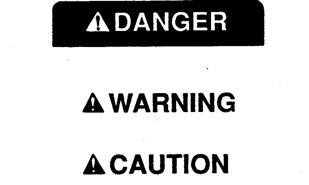
FOLLOW SAFETY INSTRUCTIONS
Carefully read all safety messages in this manual and on your machine safety signs. Keep safety signs in good condition. Replace missing or damaged safety signs. Be sure new equipment components and repair parts include the current safety signs. Replacement safety signs are available from your John Deere dealer.
Learn how to operate the machine and how to use controls properly. Do not let anyone operate without instruction.
Keep your machine in proper working condition. Unauthorized modifications to the machine may impair the function and/or safety and affect machine life.
If you do not understand any part of this manual and need assistance, contact your John Deere dealer.
T81389UN07DEC88
TS1871930SEP88
TS201UN23AUG88 DX,ALERT -19-04JUN90 DX,SIGNAL -19-09JAN92 DX,READ -19-04JUN90 Group 05 Safety TM1466 (25AUG92) 10-05-1 TRS/TRX Series Snowblowers 270995 10 05 1
HANDLE FLUIDS SAFELY—AVOID FIRES
When you work around fuel, do not smoke or work near heaters or other fire hazards.
Store flammable fluids away from fire hazards. Do not incinerate or puncture pressurized containers.

Make sure machine is clean of trash, grease, and debris. Do not store oily rags; they can ignite and burn spontaneously.
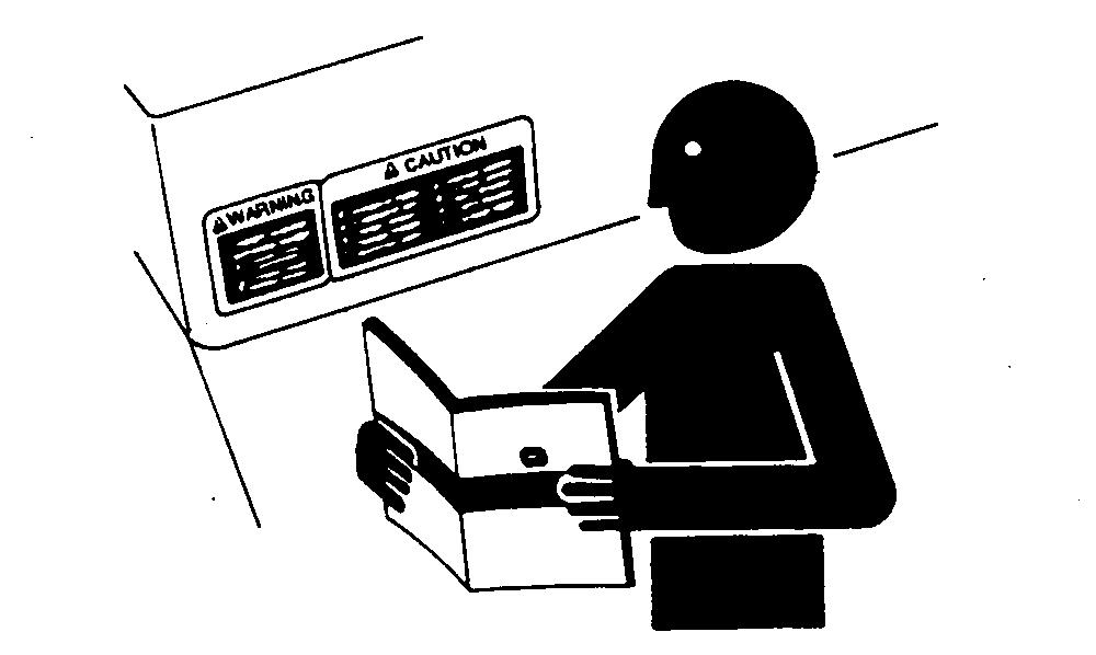
PREPARE FOR EMERGENCIES
Be prepared if a fire starts.
Keep a first aid kit and fire extinguisher handy.
Keep emergency numbers for doctors, ambulance service, hospital, and fire department near your telephone.
WEAR PROTECTIVE CLOTHING
Wear close fitting clothing and safety equipment appropriate to the job.

Prolonged exposure to loud noise can cause impairment or loss of hearing.
Wear a suitable hearing protective device such as earmuffs or earplugs to protect against objectionable or uncomfortable loud noises.
Operating equipment safely requires the full attention of the operator. Do not wear radio or music headphones while operating machine.
TS227UN23AUG88
TS291UN23AUG88
TS206UN23AUG88 DX,FLAME
DX,FIRE2
DX,WEAR -19-10SEP90 Safety TM1466 (25AUG92) 10-05-2 TRS/TRX Series Snowblowers 270995 10 05 2
-19-04JUN90
-19-04JUN90
OTHER MATERIAL
Number
Blower Housing, Cylinder Head, and Breather
Name
Use
SCOTCH-BRITE abrasive pads Remove carbon deposits from combustion chamber
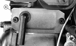
REMOVE AND INSTALL BLOWER HOUSING
IMPORTANT: Remove blower housing when engine is cold to prevent cylinder head warpage.
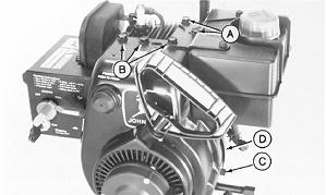
1. Loosen cap screws (A).
2. Remove cap screws (B) and (C).
3. Remove plate (D).
4. Remove blower housing.
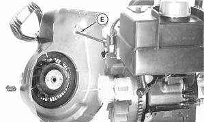
5. Disconnect hose (E) from primer bulb.
6. Inspect blower housing.
7. Connect hose (E) to primer bulb.
8. Install blower housing.
9. Install plate (D).
10. Tighten cap screws (A) and (B) to 200 lb-in. (20.3 N·m).
A—Cylinder Head Cap Screw
B—Cylinder Head Cap Screw
C—Blower Housing Cap Screw
D—Inspection Plate
E—Primer Hose
M53691UN25OCT89 M53692UN25OCT89 MX,2515FA,A1A
MX,2515FA,A1
-19-16OCT89
-19-15SEP89 Group 15
TM1466 (25AUG92) 20-15-1 TRS/TRX Series Snowblowers 270995 20 15 1
REMOVE AND INSTALL CYLINDER HEAD
1. Remove blower housing. (See this group.)
2. Remove fuel tank. (See Group 05 in this section.)
3. Remove muffler. (See Group 05 in this section.)
4. Remove spark plug.
IMPORTANT: Remove cylinder head when engine is cold to prevent cylinder head warpage.
5. Remove cylinder head, gasket and fuel tank bracket.
6. Inspect cylinder head. (See this group.)
7. Install new cylinder head gasket.
8. Install cylinder head and fuel tank bracket.
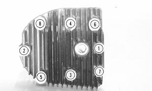
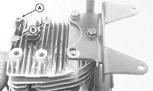
NOTE: Install special cap screw (A) and short cap screws (B) in locations shown.
9. Tighten cylinder head cap screws in sequence shown to 180 lb-in. (20.3 N·m) in 50 lb-in. (5.5 N·m) increments.
10. Install muffler and fuel tank. (See Group 05 in this section.)
11. Install spark plug. Tighten to 21 lb-ft. (28 N·m).
M53693UN25OCT89 M53694UN25OCT89
TM1466 (25AUG92) 20-15-2 TRS/TRX Series Snowblowers 270995 20 15 2
MX,2515FA,A2 -19-15SEP89
Blower Housing, Cylinder Head, and Breather/Cylinder Head
Blower Housing, Cylinder Head, and Breather/Breather
INSPECT CYLINDER HEAD
1. Remove carbon deposits from combustion chamber and gasket surface using SCOTCH-BRITE abrasive pads or equivalent.
2. Clean head with solvent.
3. Inspect for cracks or broken cooling fins.
4. Inspect gasket surface for burrs and nicks.
5. Check cylinder head for distortion on a surface plate. Check at several points around the head. Replace head if distortion is more than 0.002 in. (0.05 mm).
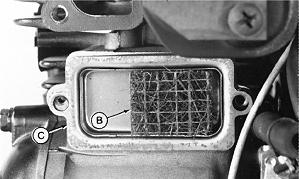
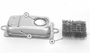
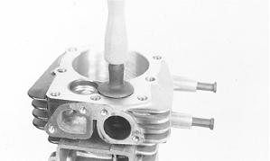
REMOVE AND INSTALL BREATHER
NOTE: Intake manifold removed for clarity.
1. Remove carburetor cover. (See Group 05 in this section.)
2. Remove cover (A) and gasket.
3. Remove element (B), bowl (C), and gasket.
4. Clean and inspect breather. (See this group.)
NOTE: Install bowl with drain hole on bottom.
5. Install gasket, bowl, and element.
6. Install gasket and cover.
7. Install carburetor cover.
M53695UN25OCT89
M53696UN25OCT89 M53697UN25OCT89
MX,2515FA,A3 -19-15SEP89
MX,2515FA,A4 -19-15SEP89
TM1466 (25AUG92) 20-15-3 TRS/TRX Series Snowblowers 270995 20 15 3
Blower Housing, Cylinder Head, and Breather/Valve Assembly
INSPECT BREATHER
1. Clean element (A) and bowl with solvent. Blow dry.
2. Check that drain hole (B) is open.
3. Check that reed valve (C) moves freely and closes when released.
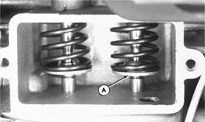
REMOVE AND INSTALL VALVE ASSEMBLY
1. Remove cylinder head. (See this group.)
2. Remove intake manifold. (See this group.)
3. Remove breather assembly. (See this group.)
4. Compress valve spring and remove retainer (A).
5. Remove and inspect valve and spring. (See this group.)
6. Install spring and retainer (A).
7. Install valves.
8. Compress valve spring. Seat retainer in groove in valve stem.
M53698UN25OCT89
M53699UN25OCT89
MX,2515FA,A5 -19-15SEP89
MX,2515FA,A6 -19-15SEP89
TM1466 (25AUG92) 20-15-4 TRS/TRX Series Snowblowers 270995 20 15 4
Blower Housing, Cylinder Head, and Breather/Valve Assembly
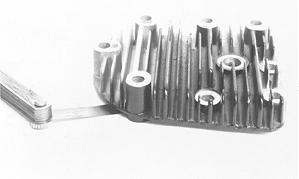
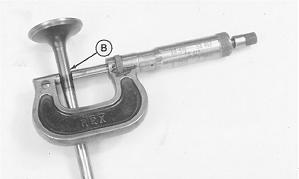
INSPECT VALVE SPRINGS
1. Clean and inspect valve springs. Replace if cracked or broken.
2. Inspect valve spring (A) for squareness on a surface plate (C). Turn spring and measure space between top spring coil and square (B).
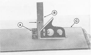
3. Measure free length of valve spring.
4. Compress valve spring. Measure compressed tension and length.
Replace valve spring if not within specifications. VALVE
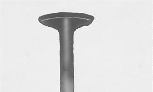
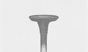
INSPECT VALVES
1. Remove carbon from valve head, face and stem with a power-operated wire brush. Be sure carbon is removed, not merely burnished.
2. Check valve for damage. Replace warped valves (A) or valves with less than 0.0312 in. (0.792 mm) margin (B).
3. Grind valve stem ends (C) square before valve-to-tappet clearance is checked.

Squareness Tolerance 0.09 in. (2.387 mm) Free Length 1.56 in. (36.690 mm) Compressed Length 0.70 in. (17.856 mm) Compressed Tension 48 lbs (21.77 kg) M53828UN06NOV89 M25949UN06NOV89
SPRING SPECIFICATIONS
M38087UN29AUG88 MX,2515FA,A7 -19-18SEP89 MX,2515FA,A8 -19-18SEP89
TM1466 (25AUG92) 20-15-5 TRS/TRX Series Snowblowers 270995 20 15 5
Blower Housing, Cylinder Head, and Breather/Valve Assembly
4. Inspect valve stem for bend using V-blocks and dial indicator. Turn valve slowly and read variation on indicator. Replace valve if variation is greater than 0.001 in. (0.03 mm).

ANALYZE VALVES
Lead deposits on the intake valve are caused by exhaust gas leakage past the valve, when using leaded gasoline.
Grind intake valve and reface seat to correct this condition.
Use unleaded fuel to prevent lead deposits.
Valve stem corrosion is caused by moisture in the engine which occurs during hot engine cool-down periods or during storage.
Fogging combustion chamber with oil before storage helps prevent corrosion.
Replace badly corroded valves.
M51753UN07SEP88
M29934UN06SEP88
M5563UN31AUG88
MX,2515FA,A9 -19-18SEP89 MX,2515A,A9A -19-11OCT89 MX,2515A,A9B -19-11OCT89
TM1466 (25AUG92) 20-15-6 TRS/TRX Series Snowblowers 270995 20 15 6
Blower Housing, Cylinder Head, and Breather/Valve Assembly
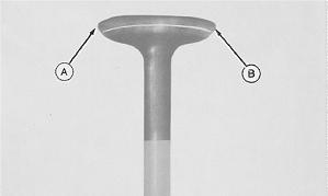
Operating at high temperatures for long periods of time can cause exhaust valve burning. Burned valve will show dark discoloration into the area protected by the valve guide. Another indication is distortion of the margin (A) and face (B). The valve seat may also show erosion.
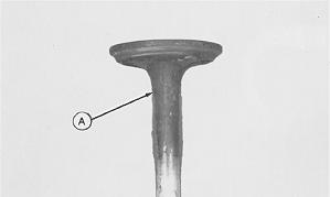
An overheated engine can cause valve burning. Check for clogged engine cooling fins. Do not run engine with blower housing removed. Also check for worn valve guides, springs or tappets, lean fuel-air mixture or incorrect spark plug.
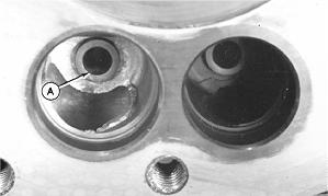
Use of old or stale gasoline can cause valves to stick.
Gummy deposits (A) build up on valve and can also gum carburetor, requiring cleaning.
Always use fresh gasoline and drain fuel tank, lines and carburetor before storage.
M30024UN06SEP88
M29936UN06SEP88
MX,2515A,A9C -19-11OCT89
MX,2515A,A9D -19-11OCT89
TM1466 (25AUG92) 20-15-7 TRS/TRX Series Snowblowers 270995 20 15 7
Blower Housing, Cylinder Head, and Breather/Valve Assembly
MEASURE VALVES AND VALVE GUIDES
1. Clean inside of valve guide (A).
2. Measure inside diameter of guide with telescoping gauge. Ream guide if not within specifications.
3. Measure outside diameter of valve stem (B). Replace valve if not within specifications.
IMPORTANT: If guide is reamed oversize, an oversize valve must be installed.
4. Replace cylinder head if guide cannot be reamed to specifications.
RECONDITION VALVE SEATS
1. Hold the valve seating surface (A) as close to 0.0469 in. (1.191 mm) as possible.

SPECIFICATIONS Valve Guide (STD) 0.312—0.313 in. (7.924—7.950 mm) Valve Guide (Oversize) 0.343—0.344 in. (8.712—8.737 mm) Valve Guide Wear Tolerance 0.0015—0.0020 in. (0.038—0.050 mm) Intake Valve Stem Diameter (STD) 0.309—0.310 in. (7.848—7.874 mm) Intake Valve Stem Diameter (Oversize) 0.340—0.341 in. (8.636—8.661 mm) Exhaust Valve Stem Diameter (STD) 0.308—0.309 in. (7.823—7.848 mm) Exhaust Valve Stem Diameter (Oversize) 0.339—0.340 in. (8.610—8.636 mm) M53700UN25OCT89 M52082UN16DEC89
A—Valve Seating D—Valve Margin Surface 0.0469 in. 0.0313 in. (1.587 (1.91 mm) mm) B—Valve Seat E—Valve Narrowing Angle (45˚) Angle (30˚) C—Valve Face Angle (45˚) M9552UN01SEP88 MX,2515FA,A10 -19-18SEP89 MX,2515FA,A9E -19-11OCT89
TM1466 (25AUG92) 20-15-8 TRS/TRX Series Snowblowers 270995 20 15 8
Blower Housing, Cylinder Head, and Breather/Valve Assembly
2. On seats with more than 0.0313 in. (0.795 mm) seating surface, cut back seating surface with a 31˚ cutter (A).
3. The valve seat angle (B) depends on valve face angle (C). New valves have a 45˚ face. Recondition valve seats with 56˚ cutter (A), to 0.0469 in. (1.19 mm).

4. Lap valves to seats after refacing.
5. Match valve to seat. Be sure valve seat is centered on valve face. The position of valve in seat is evident after lapping valve.
A—Right B—Wrong C—Wrong
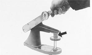
LAP VALVES
Lap valve and seat if they do not make good contact.
1. Apply a small amount of lapping compound to valve face.
2. Turn valve in seat using vacuum cup tool.
3. Check valve every eight strokes until a uniform ring appears around surface of valve face.
4. Wash parts in solvent to remove lapping compound.
5. Check position of lap mark on face. Lap mark must be on or near center of valve face.
6. Check valve-to-tappet clearance. (See Section 220, Group 15.)

M25952UN26APR89
M25953UN25APR89
M53701UN25OCT89 MX,2515FA,A9F -19-11OCT89 MX,2515FA,A9G -19-11OCT89 MX,2515FA,A11 -19-05AUG92
TM1466 (25AUG92) 20-15-9 TRS/TRX Series Snowblowers 270995 20 15 9
OTHER MATERIAL
Number
Group 20
Governor, Camshaft, and Tappets
Name
Use
T43512 Thread Lock and Sealer (Medium Apply to governor shaft. Strength)
PT569 John Deere NEVER-SEEZ® Apply to crankshaft end. Lubricant
NEVER-SEEZ is a trademark of the Emhart Chemical Group. MX,2620FA,A1A -19-05AUG92
TM1466
20-20-1 TRS/TRX
270995 20 20 1
(25AUG92)
Series Snowblowers
Suggest:
If the above button click is invalid.
Please download this document first, and then click the above link to download the complete manual.
Thank you so much for reading

REMOVE CRANKCASE COVER—TRS/TRX24 (S.N. —120000)
1. Drain oil.
IMPORTANT: Camshaft is a tight fit in crankcase cover and can come out of crankcase with cover removal. To prevent damage to camshaft lobes or tappets, rotate camshaft so sheave key (E) is at 12 o’clock position (facing cylinder head end of engine).
2. Remove cap screw (A), lock washer, and washer.
3. Remove crankshaft sheave, spacer (B), and washers.
4. Loosen set screw (C). Remove camshaft sheave and key.
5. Remove cap screw (D). Dipstick tube can be removed from crankcase, if necessary, by turning tube counterclockwise.
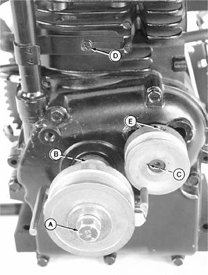
IMPORTANT: Camshaft sheave set screw can cause burrs on camshaft surface. Remove burrs before removing crankcase cover, to prevent damage to seal or camshaft bearing surface.
6. Remove crankcase cover.
A—Crankshaft Sheave Cap Screw
B—Sheave Spacer
C—Camshaft Sheave Set Screw
D—Cap Screw
E—Camshaft Sheave Key
M53702UN25OCT89
20-20-2
270995 20 20 2
MX,2520FA,A1 -19-05AUG92
Governor, Camshaft, and Tappets/Crankcase Cover—TRS/TRX24 (S.N. 120000) TM1466
(25AUG92)
TRS/TRX Series Snowblowers