TM110319 - 8235R, 8260R, 8285R, 8310R, 8335R, and 8360R Tractors
Repair (S. N. —090000) (Russia S. N. 052201—055000)
TM110319 - 8235R, 8260R, 8285R, 8310R, 8335R, and 8360R Tractors Repair (S. N. —090000) (Russia S. N. 052201 055000)
Remove Transmission
Remove Transmission
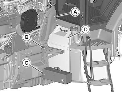
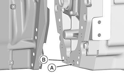
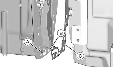
RXA0119494-UN: Shield and Tool Box
LEGEND:
A - Shield B - Step
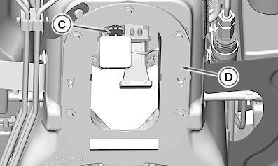
C - Tool Box
D - Battery Cover
1. Position hood forward. (See Optional Forward Hood Position in Section 80, Group 05.)
2. Discharge air conditioning system. (See Discharge Air Conditioning System in Section 90, Group 10.)
3. Drain coolant from engine block and radiator.
4. Remove shield (A) and step (B).
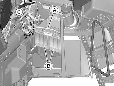
5. Remove tool box (C) and battery cover (D).
6. RXA0119496-UN: Battery Ground Cable
LEGEND:
A - Battery Ground Cable
B - Batteries (2 used)
C - Single Point Ground
Disconnect battery ground cable (A) from batteries (B) and from single point ground (C).
7. RXA0119500-UN: Left-Hand Hood Spreader
RXA0119501-UN: Right-Hand Hood Spreader
LEGEND:
A - Hood Spreaders (2 used)
Remove hood spreaders (A).
8. RXA0119553-UN: Positive Battery Cable
LEGEND:
A - Clamps (4 used)
B - Positive Battery Cable
Remove clamps (A) and positive battery cable (B).
9. Remove front weights, if equipped.
10. For tractors with Front Hitch: Remove front hitch. (See Remove and Install Front 3-Point Hitch in Section 70, Group 35.)
11. For tractors with Front PTO: Remove front PTO. (See Remove Front PTO in Section 56, Group 40.)
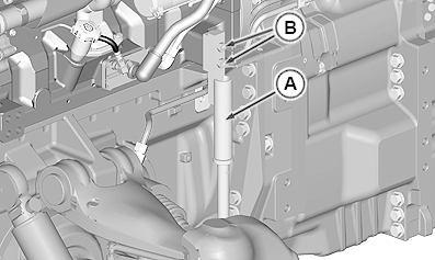
12.
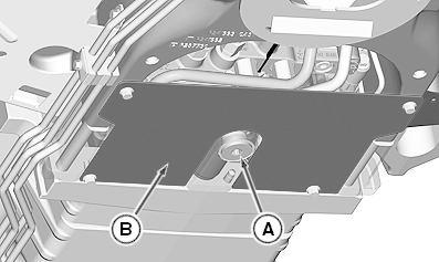
RXA0109012-UN: Transmission Drain Plug
LEGEND:
A - Plug B - Front Plate
Drain transmission by removing plug (A). (See Drain Hydraulic System in Section 70, Group 05.)
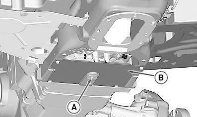
13. Remove access plate (B).
14. If equipped, remove radar sensor. (See Replace Radar Sensor in Section 40, Group 30.)
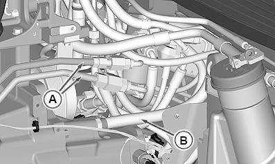
15. NOTE:
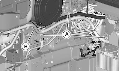
RXA0107812-UN: Left-Hand Side
RXA0107814-UN: Right-Hand Side
LEGEND:
A - Lines (5 used)
B - Clamp
Some lines use Snap-To-Connect fittings. (See Servicing and Connecting Snap-To-Connect STC™ Fittings in Section 10, Group 10.)
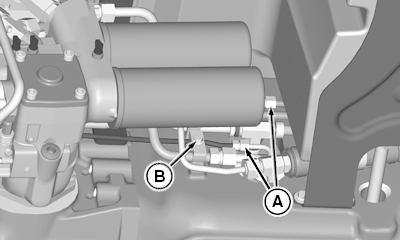
Line and hose configurations vary depending on tractor options.
Disconnect lines (A).
16. Cap and plug lines and ports to prevent contamination.
17. Remove clamp (B).
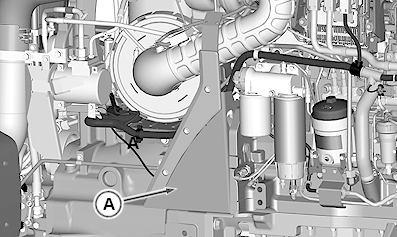
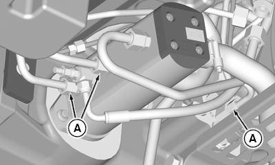
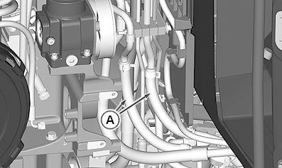
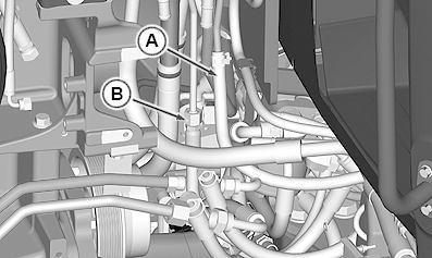
18. RXA0107813-UN: Bottom of Transmission
RXA0107811-UN: Bottom of Transmission
LEGEND:
A - Transmission Lines (6 used)
Disconnect transmission lines (A).
19. Cap and plug lines and ports to prevent contamination.
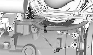
20.
RXA0125922-UN: Snap Ring and Line Clamp
LEGEND:
A - Snap Ring
B - Clamp
For tractors equipped with MFWD, perform the following:
a. Loosen MFWD drive shaft shield and remove steering line clamp (B).
b.
CAUTION:
Tractor ignition must be in the "OFF" position when checking position of MFWD drive shaft snap ring (A).
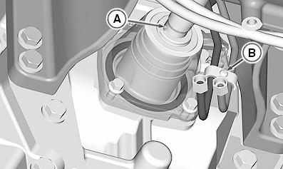
Position tractor with MFWD drive shaft snap ring (A) in downward position.
c. Disengage MFWD shaft snap ring and slide shaft forward to disengage from MFWD clutch.
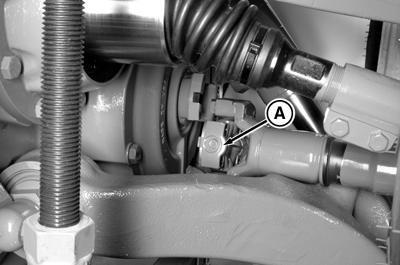
21.
RXA0056006-UN: Drive Shaft
LEGEND:
A - Drive Shaft Universal Joint
For tractors with ILS™: Disconnect one drive shaft universal joint (A) from differential yoke and support drive shaft on lower control arm.
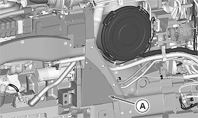
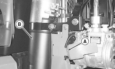
22. RXA0111687-UN: Shield and Exhaust
LEGEND:
A - Shield B - Exhaust Pipe
Remove shield (A).
23. Remove exhaust pipe (B). (See Service Exhaust System in Section 30, Group 25.)
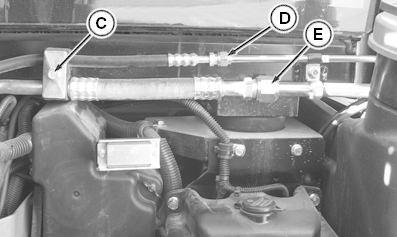
RXA0111469-UN: Cab Riser Panel
RXA0111467-UN: Air Conditioner Lines
LEGEND:
A - Cab Riser Panel
B - Cap Screws (2 used)
C - Line Clamp
D - Air Conditioning Line (High Pressure)
E - Air Conditioning Line (Low Pressure)
Remove cab riser panel (A) by removing cap screws (B) under floor mat.
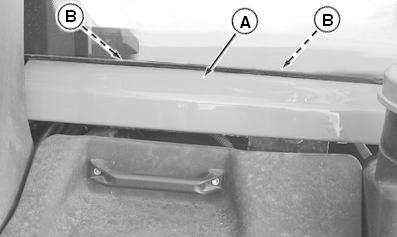
25. Remove line clamp (C).
26. Disconnect and plug air conditioner lines (D and E).
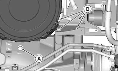
RXA0119554-UN: Alternator
LEGEND:
A - Auxiliary Drive Belt B - Alternator Wires (3 used)
C - Mounting Cap Screws (2 used)
D - Alternator
Remove auxiliary drive belt (A).
28. Identify, label, and disconnect alternator wires (B).
29. Remove mounting cap screws (C) and alternator (D).
 24.
27.
24.
27.
30.
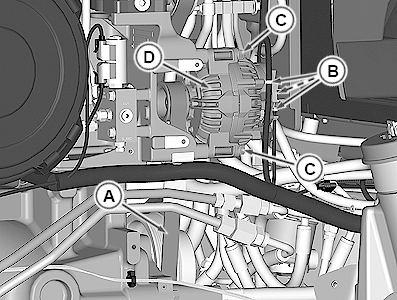
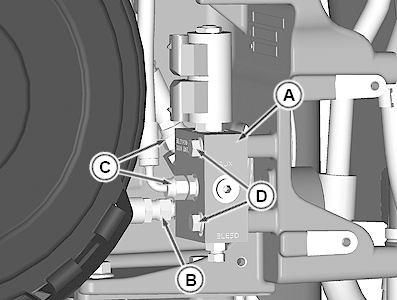
RXA0119555-UN: Fan Drive Control Valve
LEGEND:
A - Fan Drive Control Valve
B - Line
C - Lines (2 used)
D - Cap Screws (2 used)
Identify, label, and disconnect harness from fan drive control valve (A).
31. Remove line (B).
32. Disconnect lines (C).
33. Cap and plug lines and ports to prevent contamination.
34. Remove cap screws (D) and fan drive control valve.
35. RXA0119556-UN: Steering Lines and Vent Hose
LEGEND:
A - Steering Lines (2 used)
B - Vent Hose
Disconnect steering lines (A).
36. Disconnect vent hose (B).
37. RXA0119557-UN: Heater Hoses
LEGEND:
A - Heater Hoses (2 used)
Remove heater hoses (A).
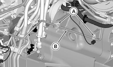
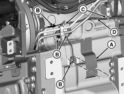
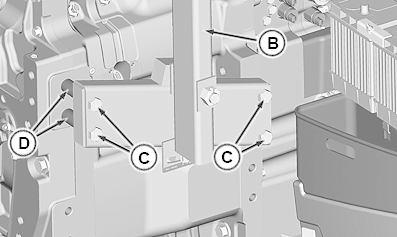
RXA0119562-UN: Harness
LEGEND:
A - Connectors (3 used)
B - Cap Screw, Clamp, and Ground Wires
C - Cap Screw
Disconnect harness connectors (A).
46. Remove cap screw, clamp, and ground wires (B).
47. Remove filter housing bracket cap screw (C).
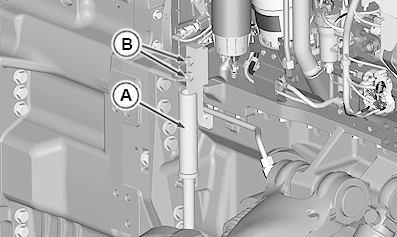
48.
RXA0119559-UN: Auxiliary Drive Bracket
LEGEND:
A - Cap Screw
B - Cap Screws (4 used)
Remove filter housing bracket cap screw (A).
49. Remove auxiliary drive bracket cap screws (B).
50.
RXA0077936-UN: Wiring Connector
LEGEND:
A - Shield
B - Wiring Connector (4 used)
C - Harness Clamps (2 used)
D - Harness
Remove shield (A).
51. Disconnect wiring connectors (B) and remove harness (D) from harness clamps (C).
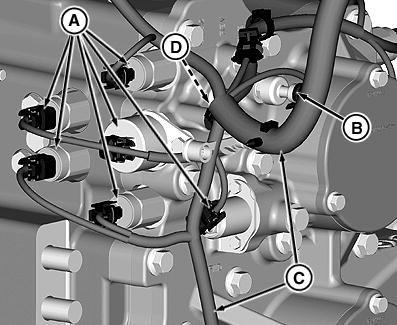
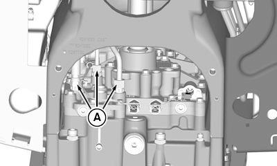
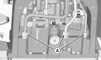
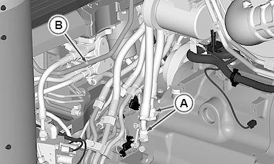
52. IMPORTANT:
RXA0080844-UN: Left-Hand Transmission Connectors
RXA0080846-UN: Right-Hand Transmission Connectors
RXA0080849-UN: Lower Half Transmission Connectors
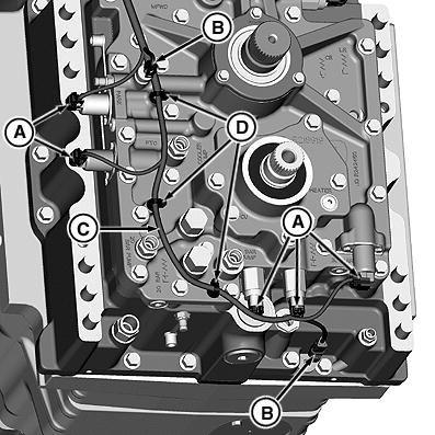
LEGEND:
A - Solenoids (13 used)
B - Sensors (5 used)
C - Harness
D - Clamps (6 used)
Note harness routing and retention. Identify and label connectors for reassembly. Identify, label, and disconnect solenoid (A) and sensor (B) connectors from transmission.
53. Note harness routing and remove harness (C) from clamps (D).
54. Move harness from mid frame to avoid damage to harness.
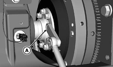
55. RXA0078566-UN: Drive Shaft
LEGEND:
A - JDG861 Torque Wrench Adapter
Disconnect drive shaft using JDG820 Flywheel Rotation Tool and JDG861 Torque Wrench Adapter (A).
56.
CAUTION:
Stand may collapse and cause injury or death if pins are not installed correctly on stand. Each tube on the stand must be pinned together with another tube. One pin may pass through all three tubes, or each pin may pass through two tubes depending on the tire size.
IMPORTANT:
Use only stands specified for stability when splitting the tractor.
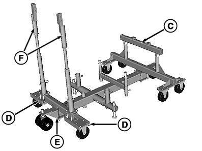
RXA0079554-UN: Splitting Stand
RXA0079555-UN: Splitting Stand for ILS™
LEGEND:
A - JT07122-6 Rear Adapter Plates
B - JT07122-1 Splitting Stand
C - JDG2061 Front Adapter
D - JT07321 Rear Support Wheels
E - JT07122-7-1 Cross Member
F - JT07122-7-2 Upright Supports
For ALL tractors, perform the following steps: Install JT07122-6 Rear Adapter Plates (A) on JT07122 Splitting Stand (B). DO NOT tighten cap screws.
57. Install JDG2061 Front Adapter (C) on JT07122 Splitting Stand. Tighten cap screws.
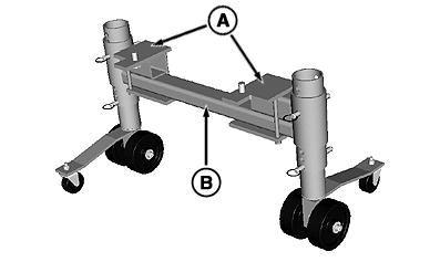
58. IMPORTANT:
Front adapter (C) must be installed tight against plate on top of splitting stand to fit correctly on tractor.
NOTE:
JT07122-7-1 Cross Member and JT07122-7-2 Upright Supports are part of JT07122-7 Upright Supports Install JT07122-7-1 Cross Member (E). DO NOT tighten cap screws.
59. Install JT07321 Rear Support Wheels (D). DO NOT tighten cap screws.
60. DO NOT install JT07122-7-2 Upright Supports (F) at this time.
61. RXA0079556-UN: Rear Splitting Stand
LEGEND:
A - Cap Screws
B - Front Support
C - Front Frame Member
D - Locating Block
Install rear splitting stand on front of mid-frame using cap screws (A). Tighten all cap screws.
62. Adjust splitting stand wheels to properly support tractor.
63. NOTE:
Depending on tractor configuration, front tires will need removed, JDG2061 Front Adapter installed, and front tires installed. (For further information on removing and installing front tires, see Operator s Manual.)
Install JDG2061 Front Adapter so front support (B) is tight under front frame member (C) and locating blocks (D) are between front frame member.
64. For tractors with ILS™: Bleed off suspension system. (See Relieve System Pressure ILS™ in Section 58, Group 05.)
65. NOTE:
 RXA0077253-UN: Front Support
RXA0119743-UN: Right-Hand Side
RXA0077253-UN: Front Support
RXA0119743-UN: Right-Hand Side
RXA0119744-UN: Left-Hand Side
LEGEND:
A - JT07122-7-2 Upright Supports (2 used)
B - Cap Screws (4 used)
JT07122-7-2 Upright Supports are part of JT07122-7 Upright Supports
Install JT07122-7-2 Upright Supports (A) on front splitting stand.
66. Attach upright supports to engine block with cap screws (B).
67. Tighten cross-member cap screws.
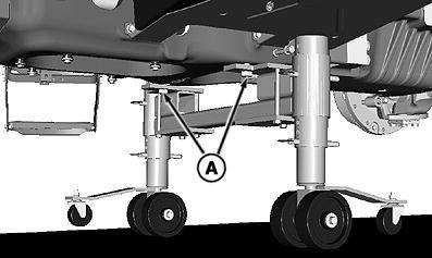
68.
RXA0119757-UN: JDG1935 Auxiliary Drive Support
LEGEND:
A - JDG1935 Auxiliary Drive Support
B - Upright Support
C - Cap Screws (2 used)
D - Bracket
E - Lifting Screw
F - Cap Screws (10 used MFWD and 2WD) (16 used ILS)
Install JDG1935 Auxiliary Drive Support (A) to left-hand upright support (B).
69. Attach support (A) to auxiliary drive with cap screws (C).
70. Position bracket (D) under air cleaner and attach to support (A).
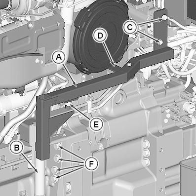
71. NOTE:
Use a prybar to assist lifting of auxiliary drive housing off dowel pins
Turn lifting screw (E) to lift auxiliary drive and air cleaner off transmission dowel pins.
72. Lower rear wheel of splitting stand so rear of engine is correctly supported.
73. Remove front frame-to-transmission cap screws (F) from both sides.
74.
CAUTION:
Avoid possible personal injury. DO NOT remove transmission-to-mid-frame cap screws. Doing so will collapse the splitting stand. Remove ONLY the front frameto-transmission cap screws.
Carefully roll front of tractor forward approximately 250 300 mm (10 12 in.).
75.
RXA0104303-UN: JT07201A Transmission Lifting Fixture and Adapter
LEGEND:
A - JT07201A Transmission Lifting Fixture
B - Cap Screw
C - JDG1883 Adapter
Drill hole in JT07201A Transmission Lifting Fixture (A). (See DFRW210 Hole Drilled in JT07201 in Section 99, Group 05.)
76. Insert JDG1883 Transmission Lifting Fixture Adapter (C) and attach with cap screw (B).
77. RXA0104302-UN: Transmission Lifting Fixture
LEGEND:
A - Cap Screw
B - MFWD and ILS Line
C - 2WD Line
Loosen cap screw (A) on JT07201A Transmission Lifting Fixture
78. Align center of cap screw with line (B) for MFWD and ILS™, or line (C) for tractors with 2WD.
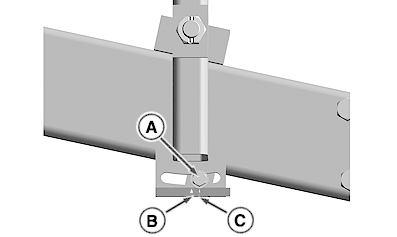
79. Tighten cap screw (A).
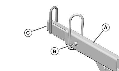
80. RXA0119758-UN: Three Cap Screws
RXA0119759-UN: JT07201 Transmission Lifting Fixture
LEGEND:
A - Cap Screws (3 used)
B - JT07201A Transmission Lifting Fixture
C - Cap Screws (4 used)
D - JDG1760 Bushing (2 used)
Remove three transmission-to-mid-frame cap screws (A).
81. Attach hoist to JT07201A Transmission Lifting Fixture (B).
82. Install fixture on transmission using cap screws (C) and two spacers from JDG1760 Spacer Kit (D) on front cap screws.
83.
CAUTION:
RXA0119760-UN: Transmission-to-Mid Frame Cap Screws
LEGEND:
A - Cap Screws (9 used)
Ensure that transmission is supported and does not drop off dowel pins or solenoid on left-hand side of transmission will be damaged.
Remove remaining transmission-to-mid-frame cap screws (A).
84. Move transmission forward and slide off drive shafts and mid-frame.
85. Lower transmission, rotate 90°, and remove from left-hand side.
AC20456,0000A59-19-20150414
TM110319 - 8235R, 8260R, 8285R, 8310R, 8335R, and 8360R Tractors
Repair (S. N. —090000) (Russia S. N. 052201—055000)
Install Transmission
Install Transmission
1. RXA0079536-UN: Mid-Frame Pilot Pins
LEGEND:
A - DFRW231 Guide Pins (2 used)
B - O-rings
Install two DFRW231 Guide Pins (A) in mid-frame.
2. Replace O-rings (B) in drive shafts.
3. Install transmission and tighten transmission-to-mid-frame cap screws to specification [Zinc-Plate Coated] .
RXA0108031-UN: Alignment Pins
LEGEND:
A - JDG768 Pilot Pins (2 used)
Install two JDG768 Pilot Pins (A) in transmission.
5. IMPORTANT:
Ensure that gasket between differential case and transmission is oriented correctly.
RXA0107117-UN: ILS O-rings
RXA0107118-UN: ILS Gasket and O-rings
LEGEND:
A - O-rings (2 used)
B - O-rings (2 used)
C - Gasket
For ILS™ Tractors: Install new O-rings (A and B) and new gasket (C).
6. Roll front of tractor to transmission.
7. Install transmission-to-engine cap screws [Zinc-Flake Coated] and tighten to specification.
8. Remove JDG1935 Auxiliary Drive Support
9. Tighten auxiliary drive support-to-transmission cap screws to specification.
10.
RXA0078566-UN: JDG861 Torque Wrench Adapter
Push engine-to-transmission drive shaft V-ring seal rearward against transmission oil seal.
11. NOTE:
Torque wrench setting will be 103 N·m (76 lb.-ft.) when used with JDG861 Torque Wrench Adapter and kept straight with torque wrench.
Torque value must be calculated for all other torque wrench adapters. (See Use Torque Wrench Adapter in Section 10, Group 10).
Use JDG861 Torque Wrench Adapter (A) to tighten engine-to-transmission drive shaft cap screws.
12. IMPORTANT:
If a failure occurred causing contamination of transmission and hydraulic system, cleanup procedures must be performed. Clean and flush differential housing and clean oil reservoir.
Fill hydraulic system. (See Fill Hydraulic System in Section 70, Group 05.)
13. For tractors with Front PTO: Install front PTO. (See Install Front PTO in Section 56, Group 40.)
14. For tractors with Front Hitch: Install front hitch. (See Remove and Install Front 3-Point Hitch in Section 70, Group 35.)
15. Purge, evacuate, and charge air conditioning system. (See Purge Air Conditioning System , Evacuate Air Conditioning System , and Charge Air Conditioning System in Section 90, Group 10.)
16.
RXA0056006-UN: Drive Shaft
LEGEND: A - Drive Shaft
For tractors with ILS™: Connect drive shaft (A) and tighten universal joint-to-differential yoke cap screws to specification.
17. NOTE:
Tractor may require jacking to remove splitting stands.
Raise tractor and remove splitting stands.
18. NOTE:
Do not overtighten manual drain valve.
Close ILS™ manual drain valve and tighten nut.
LN71218,000054E-19-20120712
TM110319 - 8235R, 8260R, 8285R, 8310R, 8335R, and 8360R Tractors
Repair (S. N. —090000) (Russia S. N. 052201—055000)
Remove Scavenge Pump
Remove Scavenge Pump
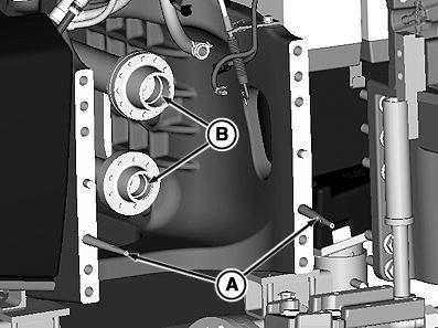
RXA0125769-UN: Transmission Drain Plug
RXA0125770-UN: Mid-Frame Bottom Plate
LEGEND:
A - Plug
B - Front Shield
C - Radar Sensor Connector
D - Plate
1. Drain transmission by removing plug (A). (See Drain Hydraulic System in Section 70, Group 05.)
2. Remove front shield (B).
3. Disconnect radar sensor connector (C), if equipped.
4. Remove bottom plate (D) from mid-frame.
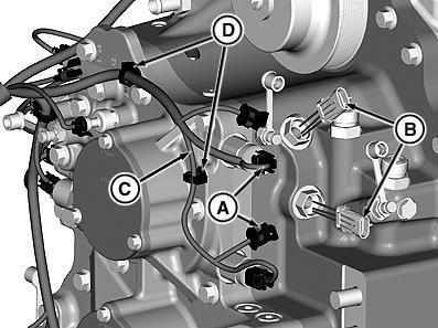
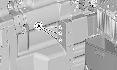
RXA0125771-UN: Lower Drive Shaft
RXA0125772-UN: Oil Line, and Fittings
LEGEND:
A - Lower Drive Shaft
B - Front Yoke
C - Rear Fitting
D - Front Fitting
E - Line
Remove shaft (A).
6. Mark position of lower drive shaft front yoke (B) in relationship to transmission case.
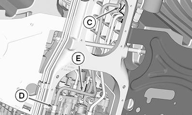
7. NOTE:
Some line or hose connections may be Snap-To-Connect fittings. (See Servicing and Connecting Snap-To-Connect STC™ Fittings in Section 10, Group 10.)
Disconnect rear fitting (C).
8. Disconnect front fitting (D) and remove line (E).
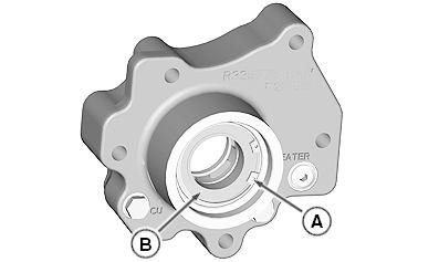
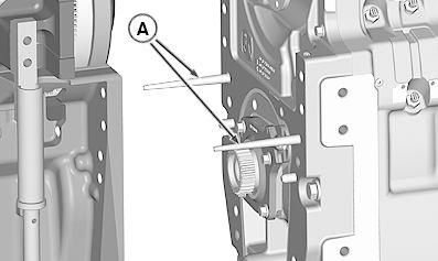
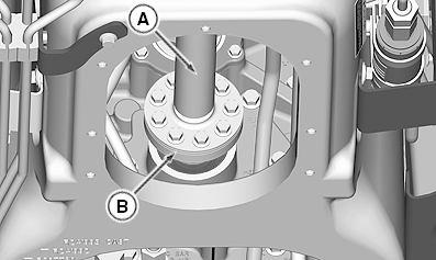
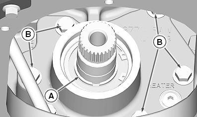
5.RXA0125660-UN: Scavenge Pump Oil Seal
LEGEND:
A - V-ring Seal
B - Oil Seal
Remove V-ring seal (A) and oil seal (B).
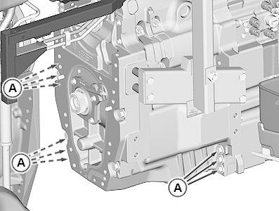
RXA0125774-UN: Scavenge Pump
LEGEND:
 9.
10.
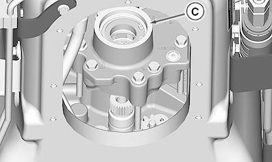
RXA0125773-UN: Scavenge Pump Cover
9.
10.
RXA0125773-UN: Scavenge Pump Cover
A - Snap Ring
B - Cap Screws (5 Used)
C - Scavenge Pump Cover
Remove snap ring (A).
11. Remove cap screws (B) and scavenge pump cover (C).
12.
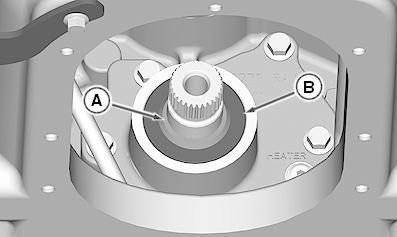
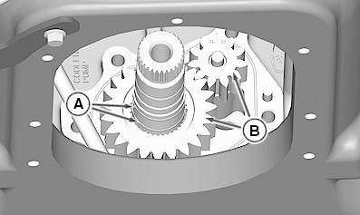
RXA0125775-UN: Shaft Seal Rings and Gears
LEGEND:
A - Seal Rings (2 Used)
B - Gears
Remove seal rings (A) from shaft.
13. NOTE:
Some pitting of gears and housing is normal. Remove and inspect gears (B).
14. NOTE:
Driver disks are part of D01044AA Bushing, Bearing and Seal Driver Set
RW35222-UN: Idler Gear
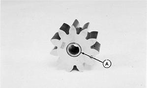
LEGEND:
A - Bearings (2 Used)
Suggest:
If the above button click is invalid.
Please download this document first, and then click the above link to download the complete manual.
Thank you so much for reading

Inspect needle roller bearings (A) and remove, if necessary, using a 16 mm (5/8 in.) driver and 13 mm (1/2 in.) pilot disks.
15. Install new bearings using a 22 mm (7/8 in.) driver and 13 mm (1/2 in.) pilot disks.
16. Install bearings flush with outer surface of pump gear.
17. RXA0125776-UN: Shaft Bearing
LEGEND:
A - Snap Ring
B - Bearing
Remove snap ring (A) and bearing (B)
18. Inspect bearing (B), replace as necessary and install in reverse order.
OURX985,00001CE-19-20120410