TM2187 - 5225,
5325, 5425, 5525, 5625, and
Technical Manual
Remove
and Install Clutch Assembly
Remove and Install Clutch Assembly
NOTE:
5325, 5425, 5525, 5625, and
and Install Clutch Assembly
Remove and Install Clutch Assembly
NOTE:
Clutch assembly can be removed and installed without any finger adjustment procedures. If clutch assembly has been disassembled for inspection or repair, see PTO Clutch Finger Adjustment and Traction Clutch Finger Adjustment procedures in Section 50, Group 10.
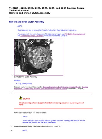
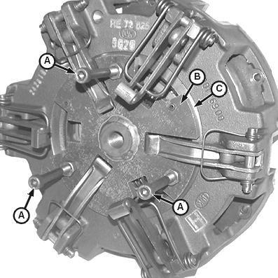
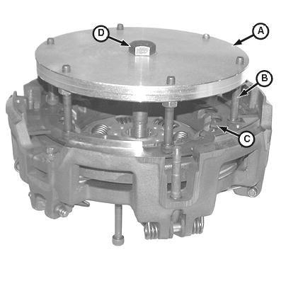
1. LV11252-UN: Clutch Assembly
LEGEND:
A - Cap Screw (6 used)
Separate engine from clutch housing. (See Separate Engine from Clutch Housing Straddle Mount or Separate Engine from Clutch Housing Isolated Open Operator Station and Cab Tractors in Section 50, Group 05.)
2.
CAUTION: Clutch assembly is heavy. Support clutch before removing cap screws to prevent personal injury.
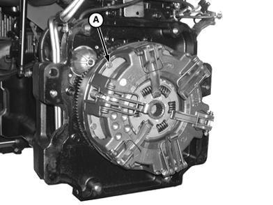
Remove six cap screws (A) and clutch assembly.
NOTE:
PTO clutch disk is loose, located between flywheel and clutch assembly after removal of clutch. Note the side of clutch disk that faces the flywheel.
3. Make repairs as necessary. (See procedures in Section 50, Group 10.)
4. NOTE:
5-cylinder tractors, from factory, are equipped with standard three-pad PTO clutch disk. All tractors are serviced with high-capacity four-pad PTO clutch disk.
Inspect and replace PTO clutch disk if friction surfaces are contaminated with grease or oil, or if thickness of disk is not within specifications.
LEGEND:
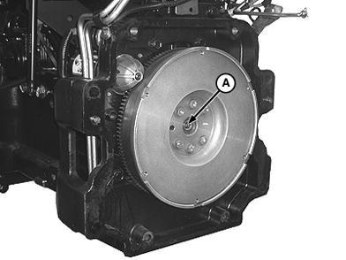
A
Inspect pilot bearing (A) for wear or damage. Replace if necessary. (See procedure in CTM104 or CTM301.)
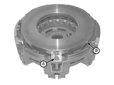
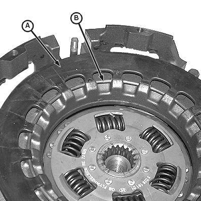
6. IMPORTANT:
When installing the PTO clutch disk (A), make sure the side of the disk stamped “Flywheel Side” faces the engine flywheel and that the alignment pins (B) face the rear of the tractor.
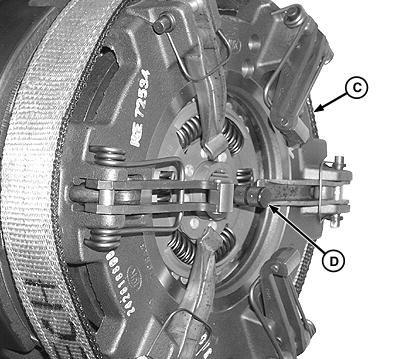
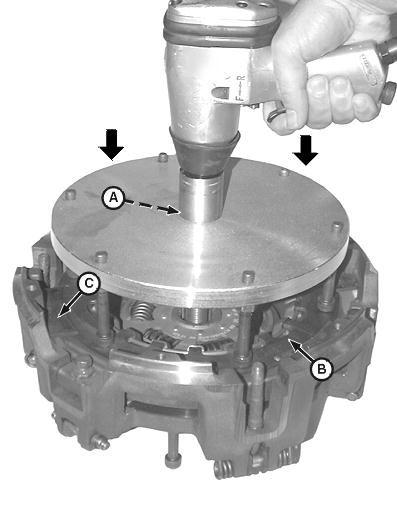
NOTE:
To aid during installation of clutch assembly to flywheel, use JDG689 clutch alignment tool (D) to align and rotate PTO clutch disk (A) while the clutch cap screws are being tightened.
5. LV11253-UN: Fly Wheel/Pilot Bearing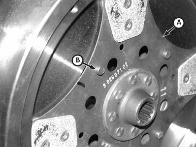
 LV5373-UN: High-Capacity Four-Pad PTO Clutch Disk Shown
LV8838-UN: SYNCSHUTTLE Clutch
LV5373-UN: High-Capacity Four-Pad PTO Clutch Disk Shown
LV8838-UN: SYNCSHUTTLE Clutch
LV8839-UN: JDG689 Alignment Tool
LEGEND:
A - PTO Clutch Disk
B - Alignment Pin (4 used)
C - Clutch Assembly
D - Clutch Alignment Tool JDG689
Install and position the PTO clutch disk (A) against the flywheel. Make sure the alignment pins (B) are facing away from engine.
7. Install the clutch assembly (C) over PTO clutch disk (A) using JDG689 Clutch Alignment Tool. Install cap screws and evenly tighten in a crisscross pattern to specification.
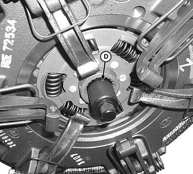
8. After cap screws are tightened to specifications, make sure PTO clutch disk rotates freely. Remove clutch alignment tool.
9. Install engine to clutch housing. (See Install Engine to Clutch Housing Straddle Mount or Install Engine to Clutch Housing Isolated Open Operator Station and Cab Tractors in Section 50, Group 05.)
TM2187 - 5225, 5325, 5425, 5525, 5625, and 5603 Tractors Repair
Disassemble and Inspect Clutch Assembly
Disassemble and Inspect Clutch Assembly
LV5351-UN: PTO Pressure Plate

LV4660-UN: Clutch
LEGEND:
A - Lock Nut (3 used)
B - PTO Pressure Plate
C - Spring (3 used)
D - Washer (3 used)
1. NOTE:
Do not reuse three lock nuts (A). New lock nuts are available through the parts catalog.
Remove three lock nuts (A) and PTO pressure plate (B). Discard three lock nuts (A) after removal.
2. Clean any rust or oil from PTO pressure plate drive surface. Inspect drive surface for distortion, cracks and heat damage. Replace if necessary.
3. Remove three springs (C) and washers (D).
4. NOTE:
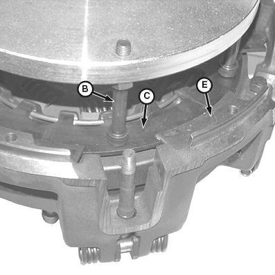
The heads of three adjustable socket head screws (A) on JDG1337 Clutch Repair Fixture are used to support the clutch assembly on a flat surface during disassembly.
LEGEND:
A - Adjustable Socket Head Screw (3 used)
B - Clutch Support Plate (Part of JDG1337)
C - Machined Surface
Install the clutch support plate (B) flush with machined surface (C) on back of clutch.
LV4662-UN: Compression Plate
LV4664-UN: Repair Fixture
LEGEND:
A - Compression Plate (Part of JDG1337)
B - Bolt (6 used)
C - Large Spring Washer
D - Bolt
E - Spring Washer Retainer (6 used)
Position clutch and support plate on flat work area.
 5.
5.
6. Install compression plate (A) on flywheel side of clutch. Adjust all six bolts (B) until touching large spring washer (C).
7. Make sure all six bolts (B) are resting on large spring washer (C) and not on any of the six spring washer retainers (E) located around the clutch.
8. Finger-tighten bolt (D) into threaded hole in center of bottom support plate.
9. IMPORTANT:
Use short bursts from a pneumatic impact wrench to tighten bolt in center of clutch compression plate until all six spring washer retainers can be removed.
LV4665-UN: Tighten Compression Plate
LEGEND:
A - Bolt
B - Large Spring Washer
C - Retainer (6 used)
Slowly tighten bolt (A) in center of compression plate to compress large spring washer (B) and remove six spring washer retainers (C).
10. After all six spring washer retainers (C) have been removed, slowly loosen bolt (A) to relieve tension of large spring washer (B).
11. Remove clutch compression plate from clutch assembly.
LV4667-UN: Large Spring Washer
LV4668-UN: Traction Clutch Pressure Plate
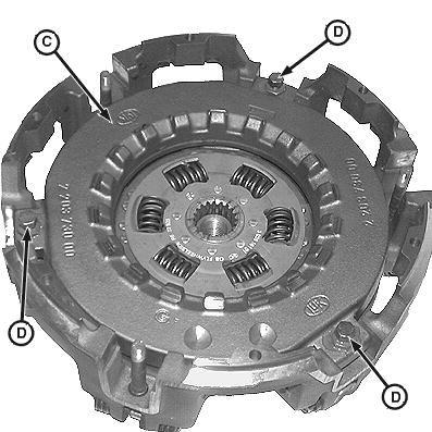
LEGEND:
A - Spring Washer
B - Ring
C - Traction Clutch Front Pressure Plate
D - Lock Nut and Cap Screw (3 used)
Remove spring washer (A) and ring (B).
13. NOTE:
12.Do not loosen or remove three lock nuts and cap screws (D) on traction clutch front pressure plate (C).
Remove traction clutch front pressure plate (C).
14. Clean any rust or oil from traction clutch front pressure plate drive surface. Inspect drive surface for distortion, cracks and heat damage. Replace if necessary.
15. NOTE:
Note the direction of raised center hub (B) to aid during installation.
LV5375-UN: Traction Clutch Disk
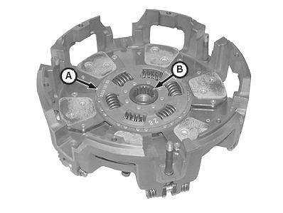
LEGEND:
A - Traction Clutch Disk
B - Center Hub
Remove traction clutch disk (A). Note the direction of center hub (B) on disk (A) to aid during installation.
16. IMPORTANT:
During inspection, if traction clutch disk thickness is within 6—6.25 mm (0.235—0.246 in.), it is recommended that the traction clutch disk be replaced.
Inspect and replace traction clutch disk if friction surfaces are contaminated with grease or oil or if thickness of disk is not within specification.
17.
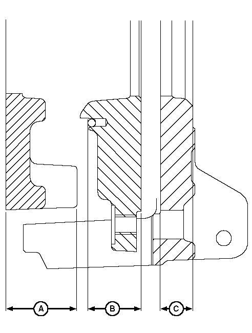
LV5379-UN: Machine Pressure Plates
LEGEND:
A - PTO Clutch Pressure Plate
B - Traction Clutch Front Pressure Plate
C - Traction Clutch Rear Pressure Plate
Machine drive surfaces of pressure plates, if necessary, until surface is free of scores, cracks and heat discoloration.
18. Measure the thickness of pressure plates at dimensions (A, B and C). Replace parts that are not within specification.
Bushing (D) is crimped. If replacing bushing, make sure new bushing is securely crimped to pin (F).
PTO clutch and traction clutch finger assemblies are serviced as separate kits. Kits are available through the parts catalog.
LV4649-UN: Clutch Release Fingers
LEGEND:
A - Traction Clutch Rear Pressure Plate
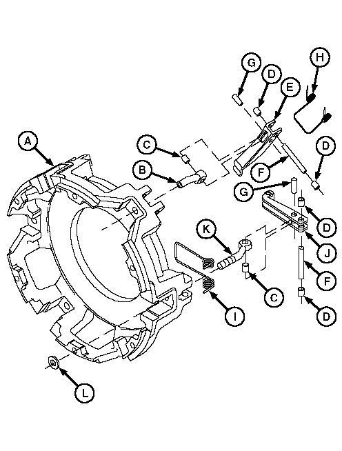
B - Adjuster (3 used)
C - Bushing (6 used)
D - Bushing (12 used)
E - Traction Clutch Release Finger (3 used)
F - Pin (6 used)
G - Pin (6 used)
H - Spring (3 used)
I - Spring (3 used)
J - PTO Clutch Release Finger (3 used)
K - Adjuster (3 used)
L - Bushing (3 used)
Disassemble parts (A L).
20. Inspect all parts for wear or damage. Replace as necessary.
21. Crimp new bushing (D) to pin (F).
22. Clean any rust or oil from traction clutch rear pressure plate drive surface. Inspect drive surface for distortion, cracks and heat damage. Replace if necessary.
JG31785,00000E7-19-20041012
TM2187 - 5225, 5325, 5425, 5525, 5625, and 5603 Tractors Repair
1. LV4661-UN: Support Plate
LEGEND:
A - Adjustable Socket Head Screw (3 used)
B - Clutch Support Plate (Part of JDG1337)
C - Machined Surface
Install support plate (B) flush with machined surface (C) on clutch.
2. Make sure adjustable socket head screws (A) all have equal lengths.
3. Place support plate and clutch on flat work area.
4. NOTE: Make sure raised hub side of traction clutch disk is facing downward.
Traction clutch disk (A) will align with threaded hub in center of support plate from JDG1337 Clutch Repair Fixture.
LV5375-UN: Traction Clutch Disk
LV4668-UN: Front Pressure Plate
LEGEND:
A - Traction Clutch Disk
B - Raised Hub
C - Traction Clutch Front Pressure Plate
D - Cap Screw (3 used)
Install traction clutch disk (A) with raised hub (B) side downward.
5. Install traction clutch front pressure plate (C). Make sure cap screws (D) seat inside adjusters.
Suggest:
If the above button click is invalid.
Please download this document first, and then click the above link to download the complete manual.
Thank you so much for reading

LV1611-UN: Spring Washer Free Height
LEGEND:
A - Spring Washer
B - Free Height Dimension
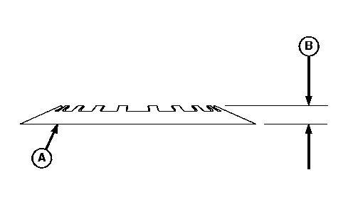
Place spring washer (A) on a workbench or any flat surface and measure free height dimension (B). Replace spring washer if less than specification.
LV4667-UN: Spring Washer and Ring
LEGEND:
6. 7.