tm1497 - 300D, 310D, 315D Backhoe Loaders Repair
Other Material
Other Material
Number
AT124243 (U.S.)
TY6305 (U.S.)
TY9485 (Canadian) 764 LOCTITE ® (LOCTITE®)
TY6304 (U.S.)
TY9484 (Canadian) 515 LOCTITE ® (LOCTITE®)
TY9375 (U.S.)
TY9480 (Canadian) 592 TEFLON ® (LOCTITE®)
TY9370 (U.S.)
TY9477 (Canadian) 242 LOCTITE ® (LOCTITE®)
T43515 (U.S.)
TY9479 (Canadian) 635 LOCTITE ® (LOCTITE®)
Name
SILASTIC 732 ® RTV Adhesive Sealant
Clean and Cure Primer Products
Flexible General Purpose Sealant Products
Pipe Sealant with Products
Thread Lock and Sealer (Medium Strength) Products
Retaining Compound (Maximum Strength) Products
SILASTIC is a registered trademark of the Dow-Corning Corp. LOCTITE is a registered trademark of Loctite Corp. TEFLON is a registered trademark of the DuPont Co.
Use
To assemble lube pump.
To clean transaxle cover, top of transaxle case, ring gear and differential housing.
To seal lube pump joint and reverser output shaft splines.
To seal MFWD transfer case quill cap screws.
To assemble lube pump and install first and second shifter shaft plug and set screws.
To assemble ring gear to differential housing.
TX0350BD298-19-1993/04/06
tm1497 - 300D, 310D, 315D Backhoe Loaders Repair Specifications
Specifications Item Measurement Specification Reverser Input Shaft End Play 0.25-2.18 mm (0.010-0.86 in.) Reverser Forward Clutch Pack Clearance 0.5-0.9 mm (.021- 036 in.) Reverser Bearing Retainer Cap Screws Torque 57-68 N·m (42-50 lb-ft) Reverse Output Yoke Nut Torque 102-115 N·m (75-85 lb-ft) Reverser Front Cover Cap Screw Torque 37-50 N·m (27-37 lb-ft) Reverser Charge Pump Cap Screw Torque 23-30 N·m (17-22 lb-ft) Axle Weight 79 kg (175 lb) Differential Assembly Weight 25 kg (55 lb) Differential Assembly Cover Cap Screws Torque 47 N·m (35 lb-ft) Differential Housing Preload 0.05-0.13 mm (0.002-0.005 in.) Differential Drive Shaft: New Bearings Rolling Drag Torque 1-3 N·m (9-27 lb-in.) Differential Drive Shaft: Used Bearing (Nominal spec) Rolling Drag Torque 0.5-2 N·m (4-18 lb-in.) Differential Drive Shaft: Differential Housing Backlash 0.15-0.20 mm (0.006-0.008 in.) Differential Drive Shaft: Differential Bearing Quill Cap Screws Torque 48 ± 5 N·m (35 ± 4 lb-ft) Differential Drive Shaft: Transmission Drive Shaft Front Bearing Cone-to-Snap Ring Maximum Gap 0.152 mm (0.006 in.) Differential Drive Shaft: Transmission Drive Shaft Quill Cap Screws Torque 47 N·m (35 lb-ft) Differential Drive Shaft: Transmission Drive Shaft End Play 0.10-0.15 mm (0.004-0.006 in.) Differential Drive Shaft: Shifter Shaft Detent Ball Springs Free length Test length 25.5 mm (0.96 in.) 16 mm at 133.5 ± 16 N (0.64 in. at 30 ± 3.5 lb) Differential Drive Shaft: Driven Gear End Play 0.05-0.10 mm (0.002-0.004 in.) Differential Drive Shaft: Output Shaft End Play 0.05-0.10 mm (0.002-0.004 in.) Differential Drive Shaft: Idler Shaft Retaining Strap Cap Screw Torque 75 N·m (55 lb-ft) Differential Drive Shaft: Drive Shaft Quill Cap Screws Torque 75 N·m (55 lb-ft)
Differential Drive Shaft: Drive Shaft End Play 0.05-0.10 mm (0.002-0.004 in.) Differential Drive Shaft: Drive Gear Quill Cap Screw Torque 72 N·m (53 lb-ft) Differential Drive Shaft: Output Shaft Quill Cap Screw Torque 75 N·m (55 lb-ft) Differential Drive Shaft: Transfer Case to Transaxle Cap Screws and Nuts Torque 115 N·m (85 lb-ft) Item Measurement Specification Lube Pump (SN -796033) Pump-toTransmission Distance 96 mm (3.78 in.) (SN 796034- ) Drive Shaft End Play 0.8-1.0 mm (0.03-0.04 in.) Item Measurement Specification Drive Shaft Lock Nut Torque 68 N·m (50 lb-ft) Second Speed Gear-310D, 315D Minimum End Play 0.07 mm (0.003 in.) TX0350BD326-19-1994/03/11
tm1497 - 300D, 310D, 315D Backhoe Loaders Repair
Reverser Repair Information
Reverser Repair Information
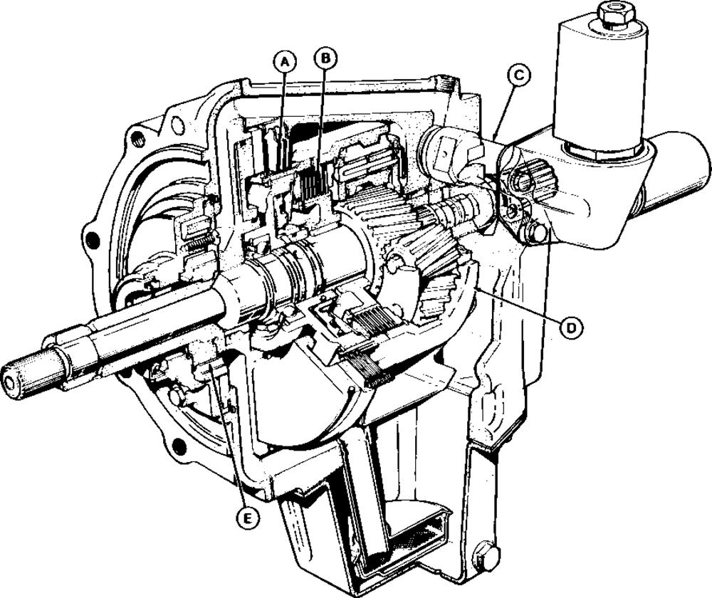
T7366BE-UN: Early Reverser Unit Shown
LEGEND:
A - Reverse Brake
B - Forward Clutch
C - Directional Control Valve
D - Planetary Assembly
E - Oil Pump
The main mechanical components of the reverser, reverse brake (A), forward clutch (B) and planetary assembly (D), are covered in this group. For repair of the hydraulic components, directional control valve (C) and oil pump (E), refer to Group 0360. For later reversers, the solenoid coils are mounted directly on the reverser case.
TX0350BD188-19-1993/04/06
tm1497 - 300D, 310D, 315D Backhoe Loaders Repair
Remove And Disassemble Front Cover And Reverse Brake
Remove And Disassemble Front Cover And Reverse Brake
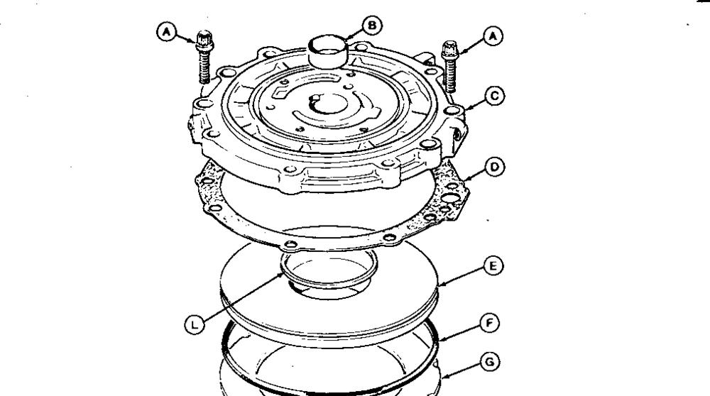
T6200AG-UN: Front Cover And Reverse Brake

LEGEND:
-
C -
D -
E -
F -
A - Screw (4 used) B
Bushing
Cover
Gasket
Piston
Packing
G - Pressure Plate
H - Dowel Pin (3 used)
I - Plate (3 used)
J - Disk (3 used)
K - Spring (11 used)
L - Packing
Inspect parts for wear or damage; replace as necessary.
Use a press to install new bushing (B) in front cover (C). Check inside diameter of bushing. Bushing should measure 34.93-34.95 mm (1.375-1.376 in.). If necessary, use a hone to obtain correct diameter.
TX0350BD189-19-1993/04/06
tm1497 - 300D, 310D, 315D Backhoe Loaders Repair
Remove And Disassemble Input Shaft And Forward Clutch
Remove And Disassemble Input Shaft And Forward Clutch
T7518AA-UN: Legend For Input Shaft And Forward Clutch
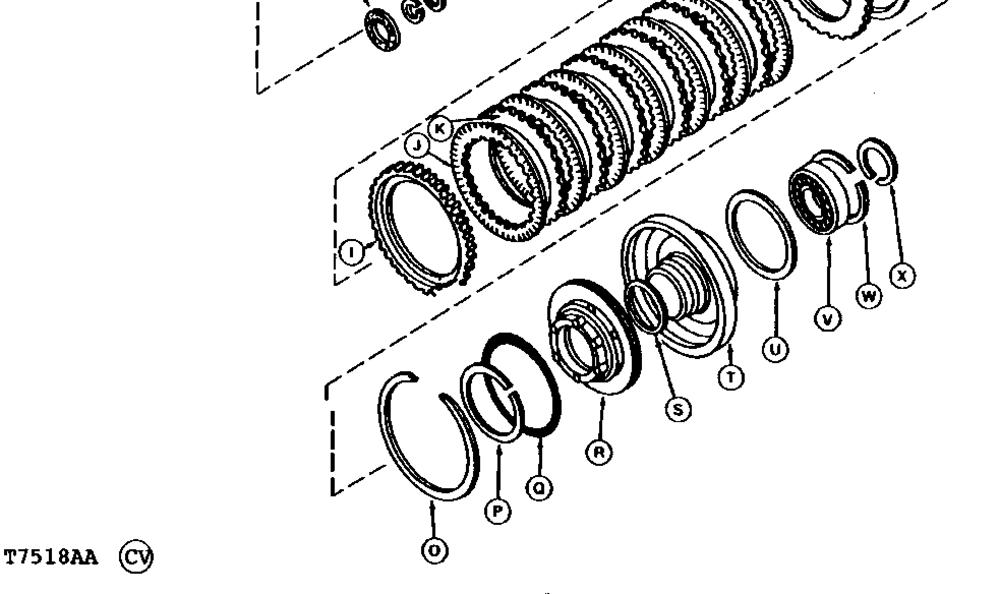
LEGEND:
A - Thrust Washer
B - Sealing Ring (2 used)
C - Shaft Key
D - Sealing Ring (2 used)
E - Snap Ring
F - Clutch Housing
G - Clutch Hub
H - Snap Ring
I - Pressure Plate
J - Disk (7 used)
K - Plate (6 used)
L - Pressure Plate
M - Snap Ring
N - Clutch Spring
O - Snap Ring
P - Bearing Ring
Q - Packing
R - Piston
S - Packing
T - Housing
U - Thrust Washer
V - Bearing
W - Snap Ring
X - Snap Ring
TXD300DS3094-19-1991/06/26
tm1497 - 300D, 310D, 315D Backhoe Loaders Repair
Remove Planetary Assembly And Bearing Retainer
Remove Planetary Assembly And Bearing Retainer
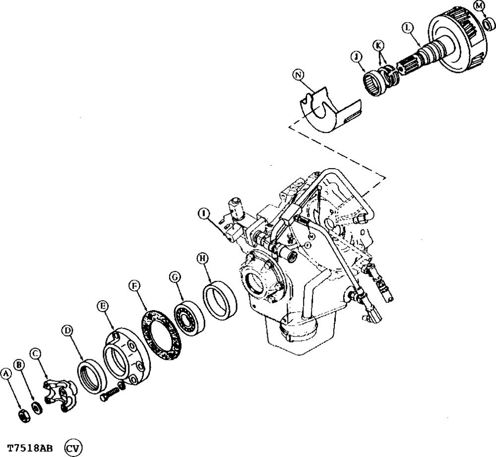
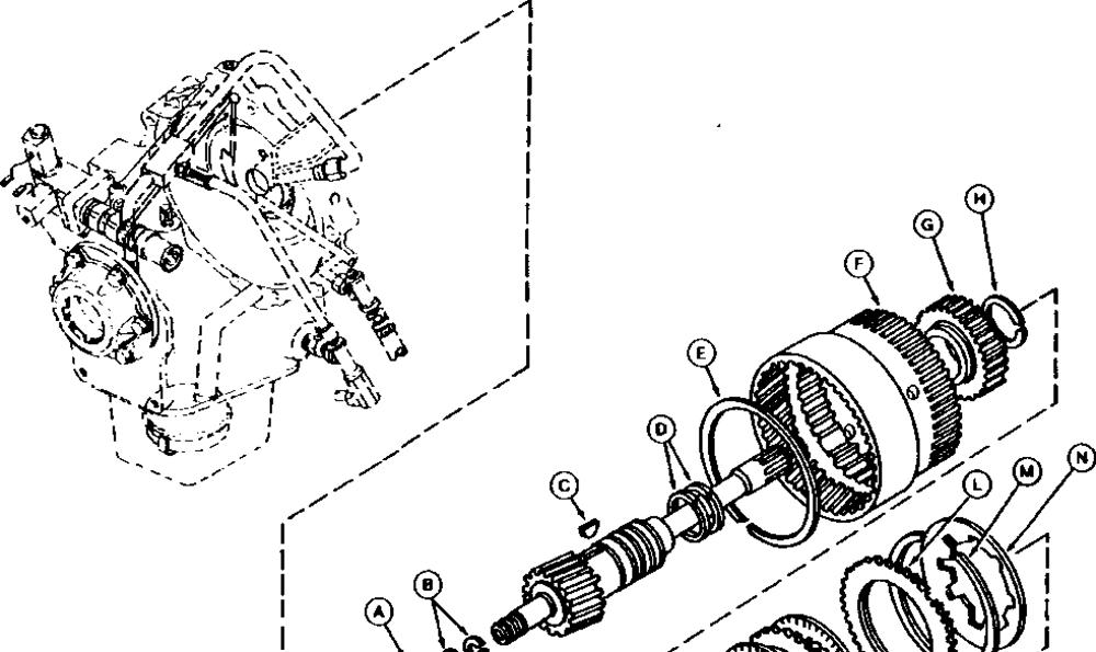
T7518AB-UN: Planetary Assembly And Bearing Retainer
LEGEND:
A - Nut
B - Washer
C - Yoke
D - Seal
E - Retainer
F - Gasket
G - Bearing
H - Sleeve
I - Housing
J - Bearing
K - Sealing Ring (2 used)
L - Planetary Assembly
M - Bearing
N - Baffle TXD300DS3096-19-1991/06/26
tm1497 - 300D, 310D, 315D Backhoe Loaders Repair
Assemble Input Shaft And Forward Clutch
Assemble Input Shaft And Forward Clutch
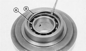
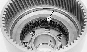
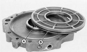
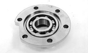
1. T5983AN-UN: Bearing And Bearing Retainer Ring
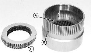
Install bearing (A) and bearing retainer ring (B).

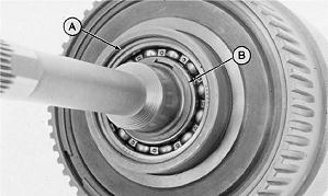
2. T5983AO-UN: Packings And Bearing Bearing Ring
Put petroleum jelly on packings. Install packings (A and B).
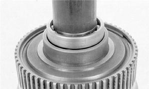
3. Install piston. Be sure packings are not rolled or damaged when installing piston.
4. Install bearing bearing ring (C).
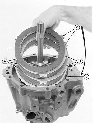
5. T7509AV-UN: Pressure Plate/Area W/o Teeth/Lube Passages
Install pressure plate (A) with smooth side facing up.
6. IMPORTANT:
DO NOT block three lube passages (B) when installing disks and plates.
Install seven disks and six plates. The area without teeth (C) on the disks must be installed over the lube passages (B).
7. Install top pressure plate with smooth side down.
8. IMPORTANT:
For correct operation, snap ring MUST be within tolerance.
T5983AR-UN: Measure Snap Ring Thickness
Measure snap ring thickness. Snap ring must be 2.3-2.4 mm (0.090-0.094 in.) thick.
9. NOTE:
Snap ring does not fit into a groove. Install correct snap ring.
10.
T7509BB-UN: Clutch Spring And Piston Assembly
Install clutch spring (A) concave side down.
11. Install piston assembly (B) using a press.
12. IMPORTANT:
For correct operation, snap ring MUST be within tolerance.
T5983AS-UN:
Measure Snap Ring Thickness
Measure snap ring thickness. Snap ring must be 1.9-2.0 mm (0.074-0.078 in.) thick.
13. Use a press to move housing enough to install snap ring into groove. Turn housing over and seat housing against snap ring using a brass drift.
14. IMPORTANT:
For correct clutch operation, end play between rear pressure plate and lip in the housing must be correct.
T5985AP-UN:
Use A Feeler Gauge To Measure The Distance
Push rear pressure plate down evenly with approximately 44.5 N (10 lb) force to remove all space between disks. Use a feeler gauge to measure the distance between rear pressure plate and lip.
15. Install correct snap ring or combination of snap rings to reduce clutch pack clearance to 0.5-0.9 mm (0.021-0.036 in.).
Item
Measurement
Clutch Pack Clearance
Two thin snap rings may be used to obtain proper clutch pack clearance.
16. NOTE:
Specification
0.5-0.9 mm (0.021-0.036 in.)
Selective snap rings have a free diameter of approximately 145.5 mm (5.68 in.). Snap rings are colored-coded to help identify the thickness of each snap ring. Use table below as a guide.
T5985AO-UN: Correct Snap Ring
Install correct snap ring (A).
17. IMPORTANT:
Shaft key (A) and key way must be aligned.
T5983AG-UN: Shaft Key
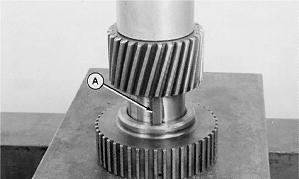
Install shaft key (A).
18. Use a press and a 2.0 ID x 2.375 OD x 8.00 in. long piece of round tubing to install gear.
19. IMPORTANT:
To prevent damage to sealing rings (A) during assembly, use petroleum jelly to hold rings in grooves.
Item Measurement Specification Snap Rings-Green Thickness 1.3-1.4 mm (0.059-0.054 in.) Snap Rings-Purple Thickness 1.5-1.6 mm (0.062-0.066 in.) Snap Rings-Orange Thickness 1.7-1.9 mm (0.074-0.078 in.) Snap Rings-Blue Thickness 2.1-2.2 mm (0.084-0.088 in.) Snap Rings-White Thickness 2.4-2.5 mm (0.096-0.100 in.) Snap Rings-Green and Orange Thickness 3.0-3.3 mm (0.124-0.132 in.)
T5984AA-UN: Sealing Rings And Snap Rings
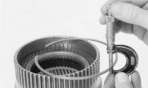
Put petroleum jelly on sealing rings. Install snap ring (B) and sealing rings (A and C). Be sure sealing rings turn freely and do not bind in shaft grooves.
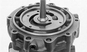
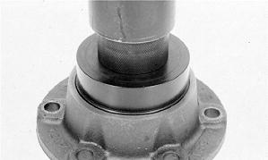
T5984AB-UN: Input Shaft
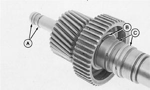
Install input shaft. Turn shaft to align splines of clutch hub with splines of disks.
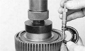
Install bearing with a press and a 1.625 ID x 2.00 OD x 8.00 in. long piece of round tubing.
T5988AA-UN: Snap Rings
Install snap rings (A and B).
TXD300DS3097-19-1991/06/26
20.
21.
22.
tm1497 - 300D, 310D, 315D Backhoe Loaders Repair
Install Input Shaft And Forward Clutch
Install Input Shaft And Forward Clutch
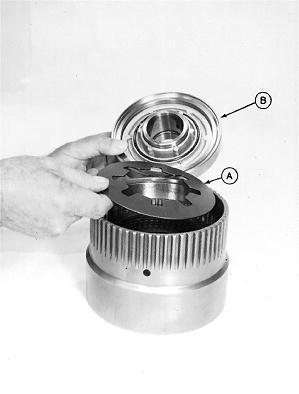
T7509AY-UN: Clutch Assembly
1. Install thrust washer.
2. Turn clutch assembly (A) when installing to align gear teeth. Use care to prevent damage to sealing rings.
TXD300DS3114-19-1991/06/26
tm1497 - 300D, 310D, 315D Backhoe Loaders Repair
Assemble And Install Reverse Brake And Front Cover
Assemble And Install Reverse Brake And Front Cover
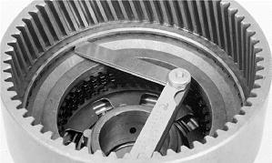
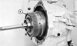
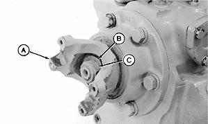
1. T5988AH-UN: Thrust Washer, Dowel Pins And Springs
Install thrust washer (C).
2. Install three dowel pins (B) in slots in housing.
3. Install eleven springs (A).
4. IMPORTANT:
When viewing the reverser from the input shaft side, install off set tabs (C) over dowel pin (D) at the 7:00 o-clock position.
Install the widest ear of the tab to the right side of the dowel pin.
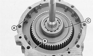
T5983AI1-UN: Disks, Plates & Off Set Tabs Over Dowel Pin
Put clean oil on disks. Install three disks (A) and three plates (B) as shown. Assemble odd-shaped lug over dowel as shown.
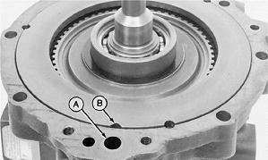
Install pressure plate with
slot (B) of pressure plate aligned with large oil hole (A) at top of case.
 5. T5988AI-UN: Press Plate W/’V’ Slot Aligned W/large Oil Hole
"V"
5. T5988AI-UN: Press Plate W/’V’ Slot Aligned W/large Oil Hole
"V"
 6. T5983AM-UN: Packings
Install new packings (A and B). Put petroleum jelly on packings.
7. Install piston.
8. T5988AS-UN: Gasket Install new gasket.
6. T5983AM-UN: Packings
Install new packings (A and B). Put petroleum jelly on packings.
7. Install piston.
8. T5988AS-UN: Gasket Install new gasket.
Item Measurement Specification Reverser Front Cover Cap
37-50 N·m (27-37 lb-ft) TXD300DS3115-19-1991/06/26
9. Install cover and cap screws. Tighten cap screws to 37-50 N·m (27-37 lb-ft).
Screws Torque
tm1497 - 300D, 310D, 315D Backhoe Loaders Repair
Transaxle-300D
Transaxle-300D
T8303AE-UN: Transaxle Diagram
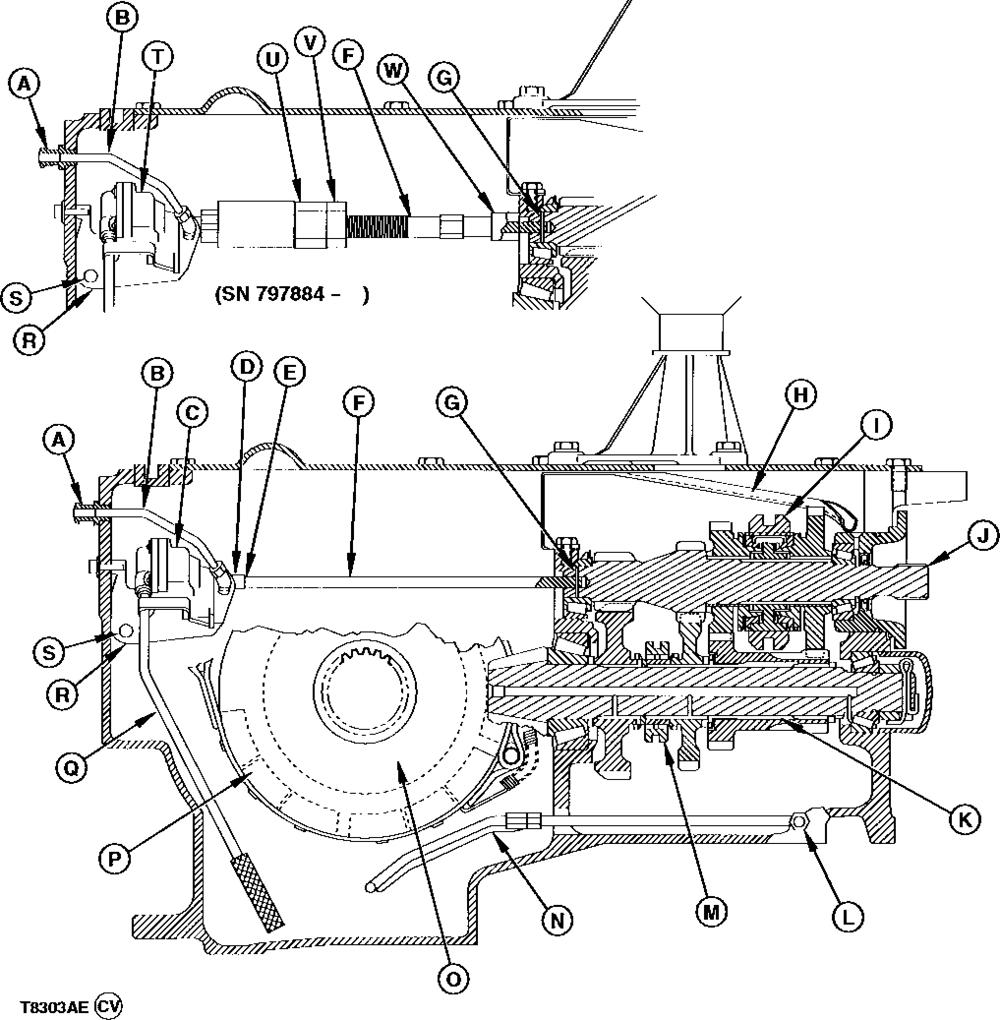
LEGEND:
A - Pump Outlet to Cooler
B - Pump Outlet Line
C - Lube Pump
D - Drive Shaft Sleeve
E - Clamp
F - Pump Drive Shaft
G - Spring Pin
H - Lube Trough
I - Third and Fourth Gear Synchronizer
J - Transmission Drive Shaft
K - Differential Drive Shaft
L - Case Inlet from Cooler
M - Shift Collar
N - Inlet Line to Brake Cavity
TX0315BA1478-19-1994/09/12
O - Ring Gear P - Parking Brake Band Q - Suction Line R - Pump Support Bracket S - Pin T - Lube Pump with Spline U - Adjustment Sleeve V - Lock Nut W - Sleeve
tm1497 - 300D, 310D, 315D Backhoe Loaders Repair
Transaxle-310D, 315D (SN -796033)
Transaxle-310D, 315D (SN -796033)
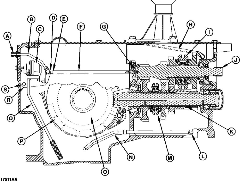
T7511AA-UN: Transaxle Diagram
TX0350DS3529-19-1994/07/12
B
C
D -
E
F -
G -
H -
I -
J -
K -
Drive Shaft L -
Cooler M -
Synchronizer N - Inlet Line
Cavity O -
Gear P - Parking
Q -
Line R - Pump Support
S - Pin
LEGEND: A - Pump Outlet to Cooler
- Pump Outlet Line
- Lube Pump
Clamp
- Drive Shaft Sleeve
Pump Drive Shaft
Spring Pin
Lube Trough
Third and Fourth Gear Synchronizer
Transmission Drive Shaft
Differential
Case Inlet from
First and Second Gear
to Brake
Ring
Brake Band
Suction
Bracket
Suggest:
If the above button click is invalid.
Please download this document first, and then click the above link to download the complete manual.
Thank you so much for reading

tm1497 - 300D, 310D, 315D Backhoe Loaders Repair
Transaxle-310D, 315D (SN 796034- )
Transaxle-310D, 315D (SN 796034- )
T8303AF-UN: Transaxle Diagram
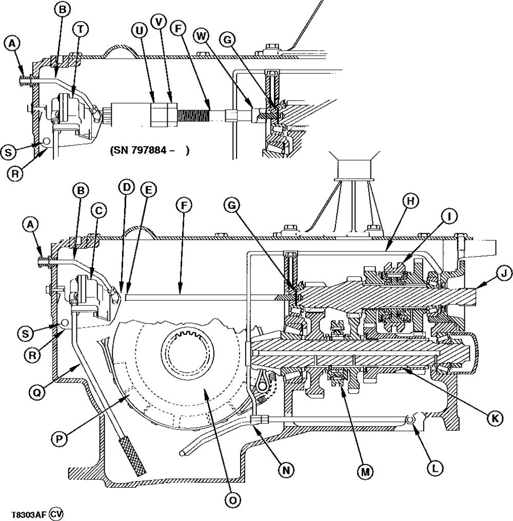
LEGEND:
A - Pump Outlet to Cooler
B - Pump Outlet Line
C - Lube Pump
D - Clamp
E - Drive Shaft Sleeve
F - Pump Drive Shaft
G - Spring Pin
H - Lube Line
I - Third and Fourth Gear Synchronizer
J - Transmission Drive Shaft K - Differential Drive Shaft
L - Case Inlet from Cooler
M - First and Second Gear Synchronizer N - Inlet Line to Brake Cavity
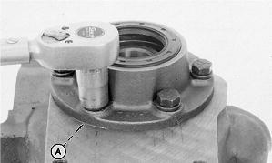
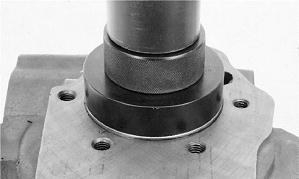 1. T5988AD-UN: Sleeve
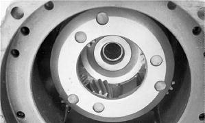
2. T5988AE-UN: Gasket
1. T5988AD-UN: Sleeve
2. T5988AE-UN: Gasket
 4.
4.