TM2356 - 27D Excavator Repair
Engine Remove and Install
Engine Remove and Install
1. TS281-UN: Avoid High-Pressure Fluids
Disconnect negative battery cable.
2. Remove counterweight. See Counterweight Remove and Install . (Group 1749.)
3.
CAUTION:
Explosive release of fluids from pressurized cooling system can cause serious burns.
Shut off engine. Remove filler cap when cool to touch. Slowly loosen filler cap to first stop to relieve pressure, then remove.
Drain coolant. See Draining Cooling System . (Operator's Manual.)
4. Drain hydraulic fluid. See Changing Hydraulic Tank Oil and Cleaning Suction Screen . (Operator's Manual.)
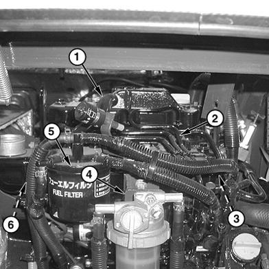
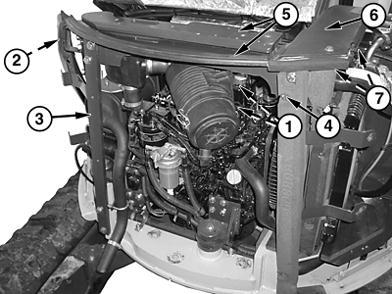
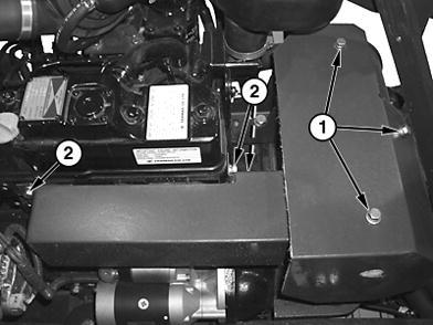
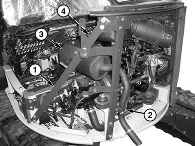
5.T207062A-UN: Engine Frame
T207063A-UN: Coolant hoses
LEGEND:
1 - Cap Screw (2 used)
2 - Left-Side Frame Bracket
3 - Left-Rear Frame Bracket
4 - Right-Rear Frame Bracket
5 - Frame Cover
6 - Frame Cover
7 - Right-Side Frame Bracket
8 - Fan Guard
9 - Coolant Hoses
10 - Inlet Fuel Line
11 - Return Fuel Line
12 - Speed Control Cable
13 - Ground Strap
Remove two cap screws (1) holding air cleaner housing.
6. NOTE: Note any shims that may accompany frame brackets for installation. Remove frame brackets (2-4) and frame cover (5).
7. Remove right-side frame bracket (7).
8. Remove air cleaner assembly.
9. Remove coolant fan guard (8) and coolant hoses (9).
10. Remove radiator. See Radiator Remove and Install (S.N. 254999) or see Radiator Remove and Install (S.N. 255000 ) . (Group 0510.)
11. Remove fan belt and fan.
12. Disconnect the inlet (10) and return (11) fuel lines.

13. Disconnect speed control cable (12) from engine.
14. Disconnect ground strap (13).
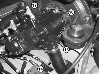
T207122A-UN: Sling and motor mounts
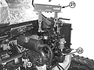
LEGEND:
14 - Hydraulic Pump Hose
15 - Inlet Flange
16 - Cap Screw (2 used)
17 - Hydraulic Pump
18 - Wire Harness-to-Alternator
19 - Wire Harness-to-Starter Motor
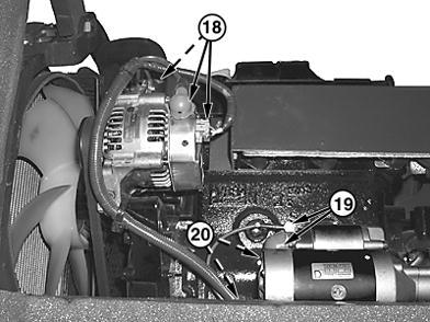
20 - Wire Harness Cap Screw (2 used)
21 - JDG23 Lifting Sling
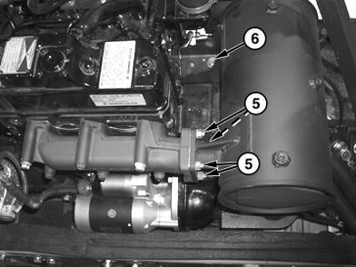
15. T207064A-UN: Hydraulic pump T207070A-UN: Starter22 - Engine Mount Cap Screw and Washer (4 used)
Disconnect hydraulic pump hose (14) and inlet flange (15).
16. Remove two cap screws (16) and pull hydraulic pump (17) away from engine until drive coupler is disengaged from flywheel and housing.
17. Disconnect wire harnesses from alternator (18) and starter motor (19).
18. Remove starter motor.
19. Remove two cap screws (20) and fasteners under starter motor securing wiring harness to engine block
20. Disconnect wiring harnesses from fuel shut-off solenoid, switches, and sensors. Attach identification tags to wiring to aid installation. See Engine Harness (W10) Component Location . (Group 9015.)
21.
CAUTION: Prevent possible injury from crushing. Heavy component, use appropriate lifting device.
IMPORTANT:
The recommended method for lifting the engine is using the JDG23 Lifting Sling. The lifting force must be at 90° to the lifting points.
Attach engine to a hoist using the JDG23 Lifting Sling (21).
22. Remove engine mount cap screws and washers (22).
23. Repair or replace parts as necessary.
24. Install engine using JDG23 Lifting Sling (21).
25. Install four engine mounts and cap screws (22). Tighten to specifications.
26. Align hydraulic pump splines to engine coupler. Tighten to specifications.
27. Connect inlet flange and hydraulic hose to pump. Tighten to specifications.
28. Fill hydraulic system.
29. Bleed hydraulic system. See Bleed Hydraulic System . (Operator's Manual.)
30. NOTE:
Before installing starter motor, install two cap screws and fasteners under starter, securing wiring harness to engine block. Install starter motor.
31. Connect engine wire harness. See Engine Harness (W10) Component Location . (Group 9015.)
32. Connect speed control cable to engine.
33. Install ground strap to frame.
34. Install fan and fan belt.
35. Adjust fan belt tension. See Inspect Fan Belt, Check and Adjust Tension . (Operator's Manual.)
36. Install radiator. See Radiator Remove and Install (S.N. 254999) or see Radiator Remove and Install (S.N. 255000 ) . (Group 0510.)
37. Fill radiator and reservoir with coolant. See Cooling System Fill and Deaeration . (Operator's Manual.)
38. Install air cleaner assembly.
39. NOTE:
Make note of any shims that were removed in the disassembly process, and place in same location of removal. Attach frame brackets to frame.
40. Attach two cap screws from the upper frame bracket-to-air cleaner.
41. Bleed fuel system. See Bleed Fuel System . (Group 0560.)
42. Install counterweight. See Counterweight Remove and Install . (Group 1749.)
43. Connect the negative battery cable.
TW73308,000043C-19-20090219
TM2356 - 27D Excavator Repair
Exhaust Manifold Remove and Install
Exhaust Manifold Remove and Install

 1. T207342A-UN: Heat Shield
T207343A-UN: Exhaust manifold
1. T207342A-UN: Heat Shield
T207343A-UN: Exhaust manifold
LEGEND:
1 - Muffler Heat Shield Cap Screw (3 used)
2 - Exhaust Manifold Heat Shield Cap Screw (3 used)
3 - Muffler-to-Exhaust Manifold Nut (4 used)
4 - Muffler Bracket Cap Screw (1 used)
5 - Exhaust Manifold Cap Screw (4 used)
6 - Exhaust Manifold Nut (2 used)
7 - Exhaust Manifold
8 - Cylinder Head Mating Surface
9 - Muffler Gasket
10 - Exhaust Manifold Gasket
Tilt operator station. See Tilting the Operator Station . (Operator's Manual.)
2. Remove cap screws (1 and 2) and washers. Remove both heat shields.
3. Remove four muffler-to-exhaust manifold nuts (3) and washers.
4. Loosen muffler bracket cap screw (4).
5. Remove four exhaust manifold cap screws (5).
6. Remove two exhaust manifold nuts (6).
7. Clean all gasket material from exhaust manifold (7) and cylinder head mating surfaces (8).
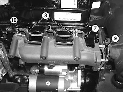
8. Install muffler gasket (9) and exhaust manifold gasket (10).
9. Install exhaust manifold cap screws and nuts. Tighten to specifications.
10. Install muffler-to-exhaust manifold nuts and muffler bracket cap screw.
11. Install exhaust manifold heat shield and muffler heat shield.
T207362A-UN: GasketTM2356 - 27D Excavator Repair
Muffler Remove and Install
Muffler Remove and Install
1. T207371A-UN: Exhaust Pipe
T207372A-UN: Muffler
LEGEND:
1 - Frame Bracket
2 - Exhaust Pipe Clamp
3 - Muffler Heat Shield
4 - Exhaust Manifold Heat Shield
5 - Muffler-to-Exhaust Manifold Nut (4 used)
6 - Muffler Bracket Cap Screw Park machine on level surface.
2. Remove counterweight. See Counterweight Remove and Install . (Group 1749.)
3. Remove left-side frame bracket (1).
4. Remove exhaust pipe clamp (2).
5. Remove heat shields to muffler (3) and exhaust manifold (4).
6. Remove four muffler-to-exhaust manifold nuts (5) and washers.
7. Remove muffler bracket cap screw (6) and remove muffler.
8. Install muffler gasket and muffler.
9. Install muffler bracket cap screw (6).
10. Install muffler-to-exhaust manifold nuts (5) and tighten.
11. Install heat shields to exhaust manifold (4) and muffler (3).
12. Install exhaust pipe clamp (2).
13. Install counterweight and left-side panels. See Counterweight Remove and Install . (Group 1749.)
MM61211,0000A43-19-20060103