TM1897 - 17ZTS Excavator
Remove and Install Steel Track
Remove and Install Steel Track
T121510-UN: Boom-to-Arm Angle and Bucket Position
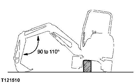
1. Swing upperstructure 90° and lower bucket to raise track off ground. Keep angle between boom and arm as shown and position round side of bucket on ground.
2.
CAUTION:
Prevent possible injury from unexpected machine movement. Put shop stands under frame to support machine while removing track.
The approximate weight of machine is 1724 kg (3800 lb).
Weight 1724 kg (3800 lb) approximate
Put blocks or stop stands under machine to support machine.
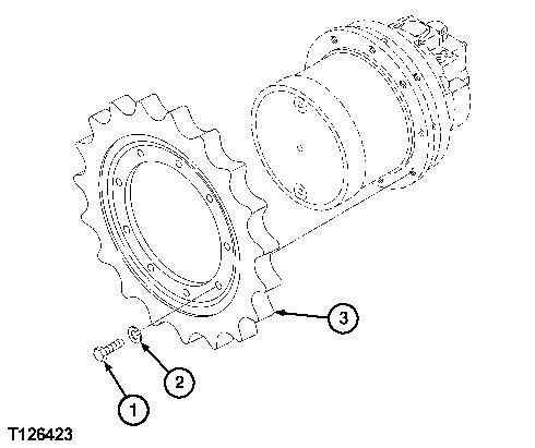
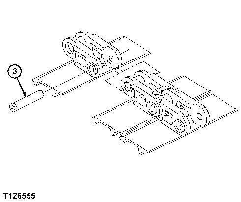
3. NOTE:
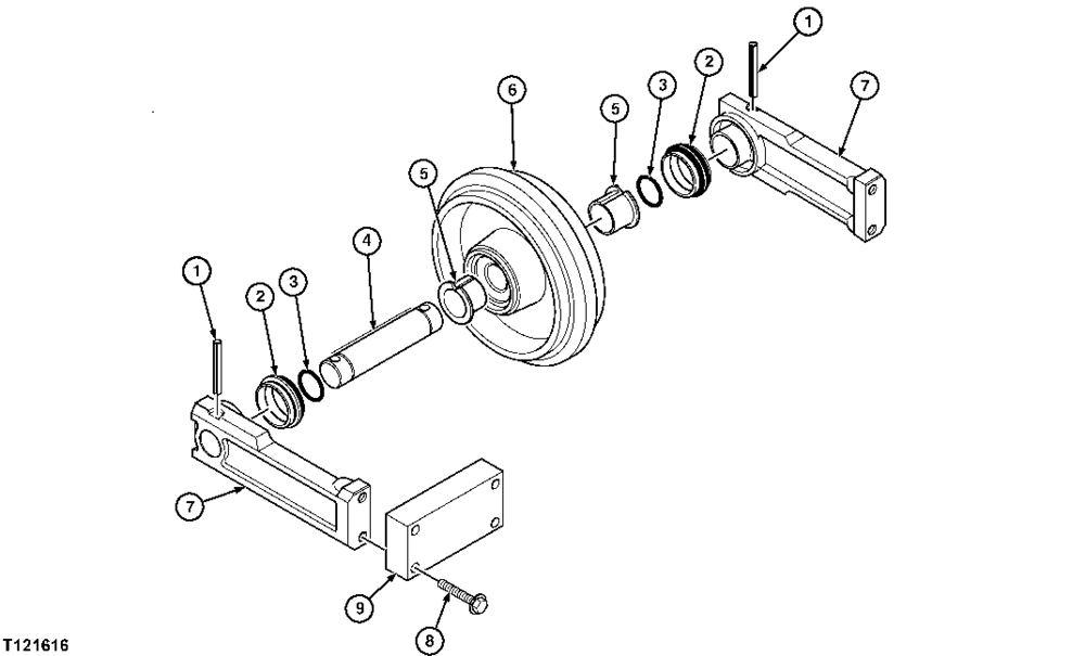
The track master pin (3) has drilled center holes on both sides of pin. It also has a head which is larger in diameter then the rest of pin.
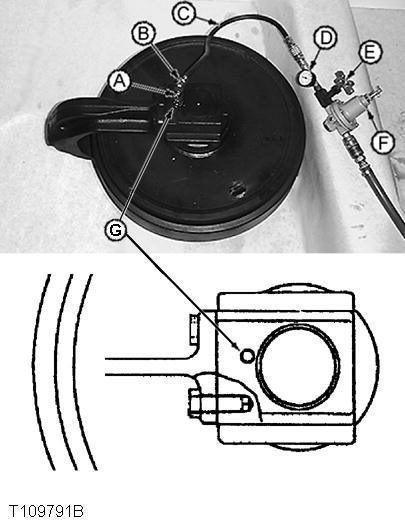
T121512-UN: Track Adjuster Valve
T126555-UN: Track Master Pin
LEGEND:
1 - Track Adjuster Valve
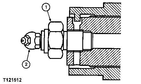
2 - Grease Fitting
3 - Track Master Pin
Rotate sprocket to position master pin (3) over front idler.
CAUTION:
High pressure grease is in track adjuster cylinder. Do not loosen track adjuster valve (1) quickly or too much. High pressure grease may cause serious injury. Never loosen grease fitting (2) to release grease.
IMPORTANT:
If gravel or mud is packed between sprocket and track, it must be removed before loosening track.
Loosen track adjuster valve (1) slowly to discharge grease. Allow track to lower completely.
4.CAUTION:
The approximate weight of steel track is 136 kg (300 lb).
Put wooden blocks in front of front idler and under track to prevent track from falling when master pin is removed.
6. Remove master pin (3).
7. Slowly turn sprocket in reverse direction to remove track from machine.
8. Repair or replace as necessary.
9. Position track on ground beneath front idler and sprocket.
10. Install end of track on sprocket teeth and slowly turn sprocket in forward direction to pull track across top of track frame to front idler.
11. Pull ends of track together and install master pin (3).
12. Adjust steel track sag. (See procedure in this group.)
TM1897 - 17ZTS Excavator
Adjust Track Sag (Rubber Track)
Adjust Track Sag (Rubber Track)
T121510-UN: Boom-to-Arm Angle and Bucket Position
-: Specifications
SPECIFICATIONS
Track Sag (Rubber Track)
Machine Weight 1724 kg (3800 lb) approximate
Track Adjuster Torque 88 N·m (65 lb-ft)
Rubber Track Sag 10-15 mm (0.4-0.6 in.)
-: Service Equipment and Tools
SERVICE EQUIPMENT AND TOOLS
Grease Gun
-: Other Material
OTHER MATERIAL
Multi-Purpose Grease
1. Swing upperstructure 90° and lower bucket to raise track off ground. Keep angle between boom and arm as shown and position round side of bucket on ground.
CAUTION:
Prevent possible injury from unexpected machine movement. Put shop stands under frame to support machine while adjusting track sag.
The approximate weight of machine is 1724 kg (3800 lb).
2.Put blocks or shop stands under the machine to support.
3. IMPORTANT:
If gravel or mud is packed between sprocket and track, it must be removed before adjusting track.
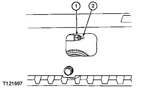 T121597-UN: Track Adjuster Valve and Grease Fitting
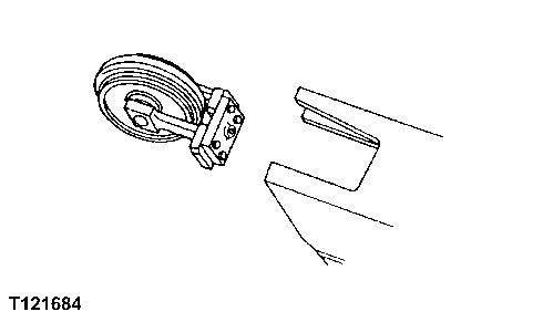
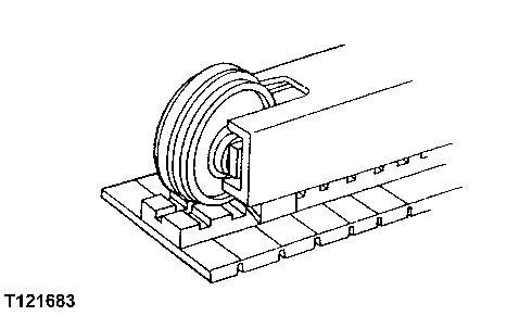
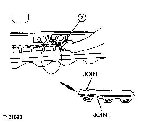
T121598-19: Position Track with Joint Section
T121597-UN: Track Adjuster Valve and Grease Fitting
T121598-19: Position Track with Joint Section
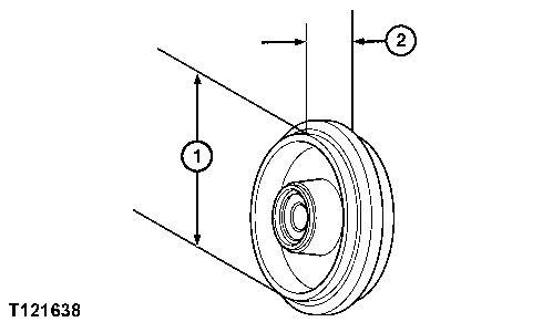
T121599-UN: Measure Rubber Track Sag
LEGEND:
1 - Track Adjuster Valve
2 - Grease Fitting
3 - Lower Roller
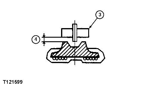
4 - Track Sag
Tighten track adjuster valve (1). Add grease through fitting (2) until most slack is removed from track.
4. Position track with joint section placed just under center lower roller (3) as shown.
5. Measure track sag (4) from lower roller (3) to track.
6.
CAUTION:
High pressure grease is in track adjuster cylinder. Do not loosen track adjuster valve (1) quickly or too much. Never loosen grease fitting (2) to release grease.
IMPORTANT:
Prevent possible damage to track components. Do not use the grease fitting on track adjuster cylinder for lubrication. Use grease fitting only for track sag adjustment.
To decrease track sag, add grease to track adjuster cylinder through grease fitting.
To increase track sag, loosen track adjuster valve to release grease from track adjuster cylinder.
Tighten track adjuster valve when track sag is correct.
TM1897 - 17ZTS Excavator
Adjust Track Sag (Steel Track)
Adjust Track Sag (Steel Track)
T121510-UN: Boom-to-Arm Angle and Bucket Position
-: Specifications
SPECIFICATIONS
Track Sag (Steel Track)
Machine Weight 1724 kg (3800 lb) approximate
Track Adjuster Torque 88 N·m (65 lb-ft)
Steel Track Sag 85-100 mm (3.3-3.9 in.)
-: Service Equipment and Tools
SERVICE EQUIPMENT AND TOOLS
Grease Gun
-: Other Material
OTHER MATERIAL
Multi-Purpose Grease
1. Swing upperstructure 90° and lower bucket to raise track off ground. Keep angle between boom and arm as shown and position round side of bucket on ground.
CAUTION:
Prevent possible injury from unexpected machine movement. Put shop stands under frame to support machine while adjusting track sag.
The approximate weight of machine is 1724 kg (3800 lb).
2.Put blocks or shop stands under the machine to support.
3. IMPORTANT:
If gravel or mud is packed between sprocket and track, it must be removed before adjusting track.
T121597-UN: Track Adjuster Valve and Grease Fitting
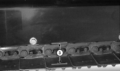
T121609-UN: Measure Rubber Track Sag
LEGEND:
1 - Track Adjuster Valve
2 - Grease Fitting
3 - Track Sag
Slowly turn track forward for two revolutions, then in reverse for two revolutions. Stop track while moving in reverse direction so all track sag is at bottom.
4. Measure track sag (3) at middle track roller from bottom of track frame to top surface of track shoe
5.
CAUTION:
High pressure grease is in track adjuster cylinder. Do not loosen track adjuster valve (1) quickly or too much. Never loosen grease fitting (2) to release grease.
IMPORTANT:
Make sure track adjuster valve is tight. Prevent possible damage to track components. Do not use the grease fitting on track adjuster cylinder for lubrication.
Use grease fitting only for track sag adjustment.
To decrease track sag, add grease to grease fitting.
To increase track sag, loosen track adjuster valve to release grease from track adjuster cylinder.
Tighten track adjuster valve when track sag is correct.