TM13326X19 - 17G Compact Excavator (PIN: 1FF017GX_ _K225001— )
Engine Remove and Install
Engine Remove and Install
-: Specifications
REMOVAL
1. Park and prepare machine for service safely. See Park and Prepare for Service Safely . (Group 0001.)
2. Disconnect battery negative (-) cable.
3. Drain cooling system. See Drain Cooling System . (Operator’s Manual.)
4. Remove canopy. See Canopy Remove and Install . (Group 1800.)
5. Remove seat. See Seat Remove and Install . (Group 1821.)
6. Remove seat platform. See Seat Platform Remove and Install . (Group 1821.)
7. Remove counterweight. See Counterweight Remove and Install . (Group 1749.)
8. Remove primary fuel filter and water separator housing. See Primary Fuel Filter and Water Separator Housing Remove and Install . (Group 0560.)
9. Remove final fuel filter housing. See Final Fuel Filter Housing Remove and Install . (Group 0560.)
10. Remove fan and fan guard. See Fan Remove and Install . (Group 0510.)
11. Remove air cleaner assembly. See Air Cleaner Assembly Remove and Install . (Group 0520.) 12.
CAUTION:
Avoid possible crushing injury from heavy component. Use appropriate lifting device.
TX1190615A-UN: Canopy Support Assembly
LEGEND:
1 - Cap Screw (2 used)
2 - Canopy Support Assembly
3 - Cap Screw (2 used)
Using appropriate lifting device, support canopy support assembly (2).
13. Remove cap screws (1 and 3).
14.
TX1190616A-UN: Canopy Support Assembly
LEGEND:
2 - Canopy Support Assembly
4 - Cap Screw (2 used)
5 - Cap Screw (2 used)
Remove cap screws (4 and 5) and canopy support assembly.
15. Remove hydraulic pump. See Hydraulic Pump 1, 2, and 3 Remove and Install . (Group 3360.)
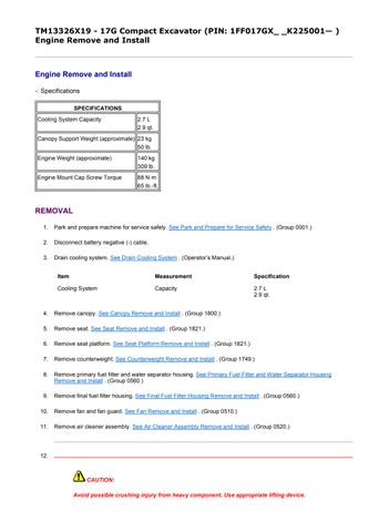
16.
TX1190623A-UN: Throttle Cable
LEGEND:
6 - Bracket
7 - Nut
8 - Throttle Cable
9 - Nut
B11 - Engine Oil Pressure Switch
Y2 - Fuel Shutoff Solenoid
Y5 - High-Altitude Solenoid
Remove nut (9) and disconnect throttle cable (8).
17. Apply alignment marks and loosen nut (7). Slide throttle cable out of bracket (6).
18. Install identification tags and disconnect engine oil pressure switch (B11).
19. Install identification tags and disconnect fuel shutoff solenoid (Y2).
20. Install identification tags and disconnect high-altitude solenoid (Y5).
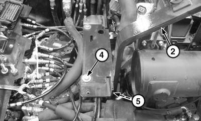
TX1190624A-UN: Engine
LEGEND:
Install identification tags and disconnect fuel hoses (10 and 11). Close all openings using caps and plugs.
22. Install identification tags and disconnect coolant hoses (12 and 13). Close all openings using caps and plugs.
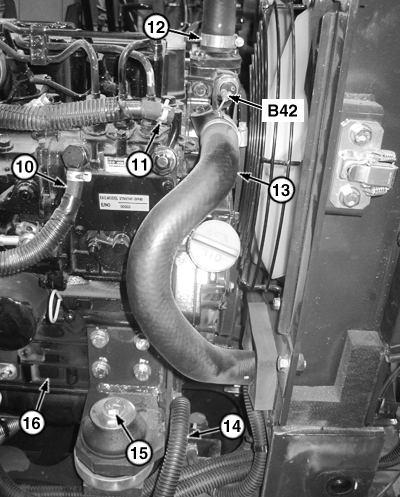
23. Install identification tags and disconnect engine overheat switch (B42).
24. Remove cap screw (14).
21.25.
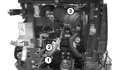
TX1190626A-UN: Engine
LEGEND:
15 - Engine Mount Cap Screw (4 used)
16 - Engine
B4 - Engine Coolant Temperature Sensor
G3 - Alternator
M1 - Starter Motor
W102 - Main Harness Ground
W103 - Floor Harness Ground
Install identification tags and disconnect engine coolant temperature sensor (B4).
26. Install identification tags and disconnect alternator (G3).
27. Install identification tags and disconnect starter motor (M1).

28. Install identification tags and disconnect harness grounds (W102 and W103).
29.
CAUTION:
Avoid possible crushing injury from heavy component. Use appropriate lifting device.
Using appropriate lifting device, support engine.
30. Remove engine mount cap screws (15) and remove engine.
31. Inspect and replace parts as necessary.
INSTALLATION
Installation is reverse of removal procedure.
CAUTION: Avoid possible crushing injury from heavy component. Use appropriate lifting device.
Using appropriate lifting device, install engine and engine mount cap screws. Tighten to specification.
CAUTION: Avoid possible crushing injury from heavy component. Use appropriate lifting device.
Using appropriate lifting device, install canopy support assembly.
Fill cooling system. See Cooling System Fill and Deaeration Procedure . (Operator’s Manual.)
TM13326X19 - 17G Compact Excavator (PIN: 1FF017GX_ _K225001— )
Radiator Remove and Install
Radiator Remove and Install
-: Specifications
REMOVAL
1. Park and prepare machine for service safely. See Park and Prepare for Service Safely . (Group 0001.)
2. Drain cooling system. See Drain Cooling System . (Operator’s Manual.)
3. Remove counterweight. See Counterweight Remove and Install . (Group 1749.)

6.
TX1190722A-UN: Rubber Cap
LEGEND:
1 - Rubber Cap Remove rubber cap (1).
TX1190724A-UN: Radiator Hoses
LEGEND:
2 - Upper Radiator Hose
3 - Clamp
4 - Lower Radiator Hose
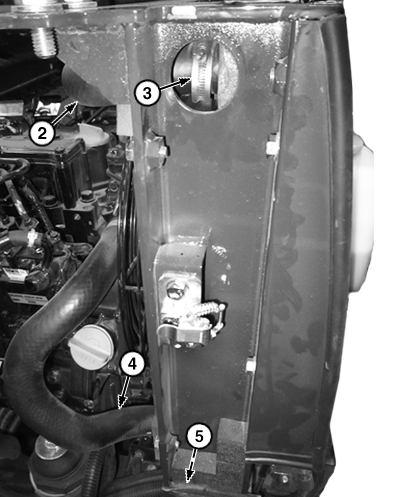
5 - Clamp
Loosen clamp (3) and disconnect upper radiator hose (2). Close all openings using caps and plugs.
and disconnect lower radiator hose (4). Close all openings using caps and plugs.
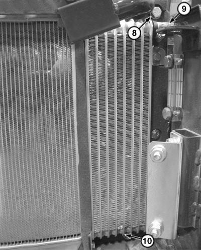
5. Loosen clamp (5) 7. Remove battery. See Replacing Battery . (Operator’s Manual.)8. TX1190726A-UN: Radiator
LEGEND:
6 - Coolant Recovery Tank
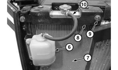
7 - Radiator
8 - Bracket
9 - Cap Screw (2 used)
10 - Deaeration Hose
Remove coolant recovery tank (6). See Coolant Recovery Tank Remove and Install . (Group 0510.)
9. Remove cap screws (9) and bracket (8).
10. Disconnect deaeration hose (10).
11. Remove radiator (7).
12. Repair or replace parts as necessary.
INSTALLATION
Installation is reverse of removal procedure.
MM12851,0000517-19-20150423
TM13326X19 - 17G Compact Excavator (PIN: 1FF017GX_
Hydraulic Oil Cooler Remove and Install
Hydraulic Oil Cooler Remove and Install
-: Specifications
REMOVAL
_K225001— )
1. Park and prepare machine for service safely. See Park and Prepare for Service Safely . (Group 0001.)
2.
CAUTION:
Avoid personal injury from high-pressure fluid. High-pressure release of oil from pressurized system can cause serious burns or penetrating injury. Slowly loosen hydraulic oil tank cap to release pressure.
Release hydraulic oil tank pressure by slowly loosening hydraulic oil tank cap. See Hydraulic Oil Tank Pressure Release Procedure . (Group 9025-25.)
3. Drain hydraulic oil tank. See Drain and Refill Hydraulic Tank Oil and Clean Suction Screen . (Operator’s Manual.)
4. TX1189862-UN: Access Door
2 - Cap Screw (2 used) 3
Cover
4 - Cap Screw (3 used)
5 - Cap Screw (4 used) 6 - Cover
Remove cap screws (2) and access door (1).
5. Remove battery. See Replacing Battery . (Operator’s Manual.)
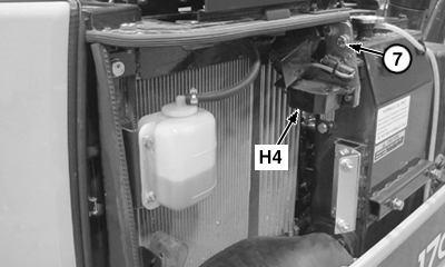
6. TX1190551A-UN: Travel Alarm
LEGEND:
7 - Cap Screw (2 used)
H4 - Travel Alarm
Remove cap screws (7) and travel alarm (H4).
7. TX1190550A-UN: Hydraulic Oil Cooler
LEGEND:
8 - Cap Screw (4 used)
9 - Hydraulic Hose (2 used)
10 - Hydraulic Oil Cooler
Install identification tags and disconnect hydraulic hoses (9). Close all openings using caps and plugs.
8. Remove cap screws (8) and hydraulic oil cooler (10).
9. Repair or replace parts as necessary.
INSTALLATION
Installation is reverse of removal procedure.
MM12851,0000518-19-20150429
TM13326X19 - 17G Compact Excavator (PIN: 1FF017GX_ _K225001— )
Fan Remove and Install
Fan Remove and Install
REMOVAL
1. Park and prepare machine for service safely. See Park and Prepare for Service Safely . (Group 0001.)
2. Remove radiator. See Radiator Remove and Install . (Group 0510.)
3. Remove fan belt. See Check and Adjust Fan Belt Tension . (Operator s Manual.)
4. TX1190638-UN: Cooling Fan
LEGEND:
1 - Cap Screw (4 used)
2 - Fan Remove cap screws (1) and fan (2).
5. Repair or replace parts as necessary.
INSTALLATION
Installation is reverse of removal procedure.
MM12851,0000519-19-20150423
TM13326X19 - 17G Compact Excavator (PIN: 1FF017GX_ _K225001— )
Coolant Recovery Tank Remove and Install
Coolant Recovery Tank Remove and Install
REMOVAL
1. Park and prepare machine for service safely. See Park and Prepare for Service Safely . (Group 0001.)
2. TX1187980A-UN: Coolant Recovery Tank
LEGEND:
1 - Cap Screw (2 used)
2 - Coolant Hose
3 - Coolant Recovery Tank
Install clamps on coolant hose (2).
3. Install identification tags and disconnect coolant hose. Close all openings using caps and plugs.
4. Remove cap screws (1) and coolant recovery tank (3). Dispose of coolant properly.
5. Repair or replace parts as necessary.

INSTALLATION
Installation is reverse of removal procedure.
Suggest:
If the above button click is invalid.
Please download this document first, and then click the above link to download the complete manual.
Thank you so much for reading

TM13326X19 - 17G Compact Excavator (PIN: 1FF017GX_ _K225001— )
Air Cleaner Assembly Remove and Install
Air Cleaner Assembly Remove and Install
REMOVAL
1. Park and prepare machine for service safely. See Park and Prepare for Service Safely . (Group 0001.)
2. TX1190548A-UN: Air Cleaner Assembly
LEGEND:
1 - Cap Screw (2 used)
2 - Air Tube
3 - Air Cleaner Assembly

4 - Intake Tube
Install identification tags and disconnect air tube (2). Close all openings using caps and plugs.
3. Install identification tags and disconnect intake tube (4). Close all openings using caps and plugs.
4. Remove cap screws (1) and air cleaner assembly (3).
5. Repair or replace parts as necessary.
INSTALLATION
Installation is reverse of removal procedure.