M325D MH EXCAVATOR
Shutdown SIS
Previous Screen
Product: EXCAVATOR
Model: M325D MH EXCAVATOR EDF
Configuration: M325D Material Handler EDF00001-01999 (MACHINE) POWERED BY C-7 Engine
Disassembly and Assembly
M325D Material Handler Power Train
Axle Shaft - Remove - Steering Axle
SMCS - 3259-011; 3278-011; 3282-011-JF
Removal Procedure Table 1
Required Tools
Media Number -RENR9720-00 Publication Date -01/05/2009 Date Updated -14/05/2009 i02265416
Tool Part Number Part Description Qty A 8T-3666 Bolt 2 B 154-6182 Forcing Bolt 2 C 138-7575 Link Bracket 1 D 1U-9200 Lever Puller Hoist 1 E 3S-6224 Electric Hydraulic Pump Gp 1 1U-7538 Double Acting Cylinder 1 5F-7693 Spacer As 1 123-4370 Stud Puller 1 8T-4131 Nut 1 8T-4123 Plated Washer 1 F 1P-1861 Retaining Ring Pliers 1 G 140-0169 Internal Puller As 1 H 140-0168 Puller 1
Care must be taken to ensure that fluids are contained during performance of inspection, maintenance, testing, adjusting and repair of the product. Be prepared to collect the fluid with suitable containers before opening any compartment or disassembling any component containing fluids.
Refer to Special Publication, NENG2500, "Caterpillar Tools and Shop Products Guide" for tools and supplies suitable to collect and contain fluids on Caterpillar products.
Dispose of all fluids according to local regulations and mandates.
1. Remove plug (1). Drain the oil into a suitable container for storage or for disposal.

NOTICE
Illustration 1
g01136679
Illustration 2
g01136680
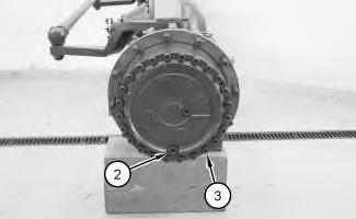
2. Remove plug (2). Drain the oil into a suitable container for storage or for disposal. Remove bolts (3) .
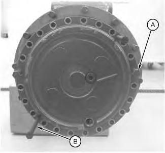
3. Install Tooling (A) and Tooling (B) .
4. Slide final drive (4) outward. Attach Tooling (C) and a suitable lifting device onto final drive (4). The weight of final drive (4) is approximately 52 kg (115 lb). Remove Tooling (A) and Tooling (B) .
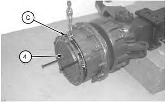
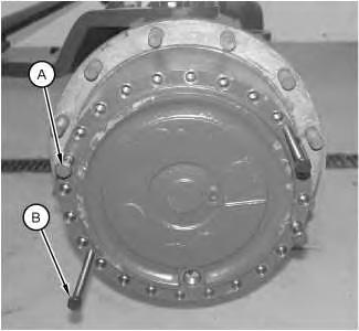 Illustration 3
g01136685
Illustration 4
g01136686
Illustration 3
g01136685
Illustration 4
g01136686
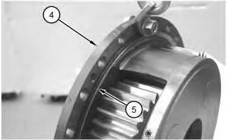
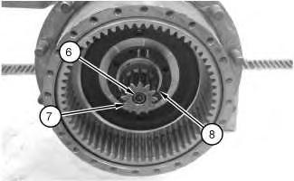
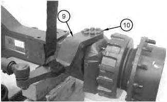 Illustration 5
g01136687
5. Remove final drive (4). Remove O-ring seal (5) .
Illustration 6
g01136688
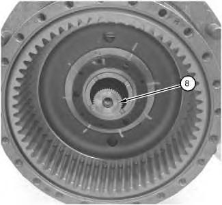
6. Remove bolt (6), sun gear (7), and sleeve (8) .
Illustration 7
g01136690
Illustration 5
g01136687
5. Remove final drive (4). Remove O-ring seal (5) .
Illustration 6
g01136688
6. Remove bolt (6), sun gear (7), and sleeve (8) .
Illustration 7
g01136690
7. Attach a suitable lifting device onto lever (9). Remove bolts (10) and position lever (9) out of the way.
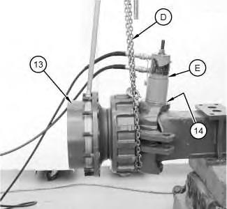
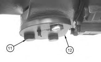
Illustration 8 g01136692
8. Remove bolts (11). Remove cover (12) .
Illustration 9 g01136693
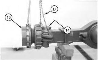
9. Attach Tooling (D) and a suitable lifting device onto hub assembly (13). The weight of hub assembly (13) is approximately 246 kg (542 lb). Attach Tooling (E) in order to remove pin (14). Do not exceed 44126 kPa (6400 psi). Remove pin (14). Repeat for the other side.
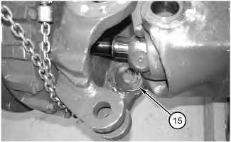
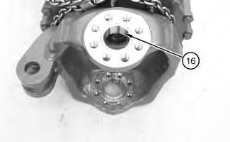
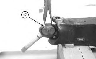 Illustration 10 g01136716
10. Note the location of shim (15) .
Illustration 11 g01136720
11. Remove bushing (16) .
Illustration 12 g01136735
Illustration 10 g01136716
10. Note the location of shim (15) .
Illustration 11 g01136720
11. Remove bushing (16) .
Illustration 12 g01136735
12. Attach a suitable lifting device onto axle shaft (17). The weight of axle shaft (17) is approximately 34 kg (75 lb). Remove axle shaft (17) .
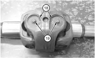
Illustration 13 g01136723
13. Use Tooling (F) in order to remove retaining rings (18). Remove plugs (19) .
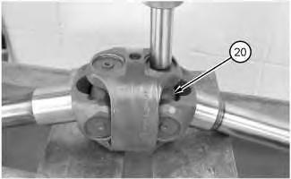
Illustration 14 g01136749
14. Use a suitable press and remove U-joints (20) .
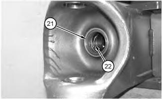
15. Use Tooling (G) and Tooling (H) in order to remove seal (21) and bushing (22). Repeat for the seal and the bushing in hub assembly (13). Hub assembly (13) is not shown.
Copyright 1993 - 2020 Caterpillar Inc. All Rights Reserved. Private
15
Illustration
g01136750
Thu Nov 26 13:43:01 UTC+0800 2020
Network For SIS Licensees.
Previous Screen
Product: EXCAVATOR
Model: M325D MH EXCAVATOR EDF
Configuration: M325D Material Handler EDF00001-01999 (MACHINE) POWERED BY C-7 Engine
Disassembly and Assembly
M325D Material Handler Power Train
Axle Shaft - Remove - Fixed Axle
SMCS - 3259-011; 3278-011; 3282-011-JF
Removal Procedure Table 1
Required Tools
Start By:
A. Remove the tire and rim. Refer to Disassembly and Assembly, "Tire and Rim - Remove".
NOTICE
Care must be taken to ensure that fluids are contained during performance of inspection, maintenance, testing, adjusting and repair of the product. Be prepared to collect the fluid with suitable containers before opening any compartment or disassembling any component containing fluids.
Refer to Special Publication, NENG2500, "Caterpillar Tools and Shop Products Guide" for tools and supplies suitable to collect and contain fluids on Caterpillar products.
Shutdown SIS
Media Number -RENR9720-00 Publication Date -01/05/2009 Date Updated -14/05/2009 i02063199
Tool Part Number Part Description Qty A 8T-3666 Bolt 2 B 154-6182 Forcing Bolt 2 C 138-7575 Link Bracket 1 D - Loctite 262 1
Dispose of all fluids according to local regulations and mandates.
1. Remove plug (1) and drain the oil into a suitable container for storage or disposal.
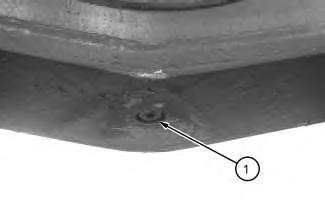
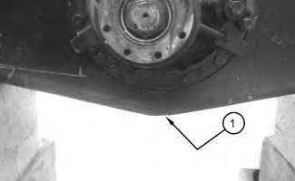 Illustration 1
g01133286
Illustration 2
g01133289
Illustration 1
g01133286
Illustration 2
g01133289
Illustration 3
g01057338
2. Remove plug (2) and drain the oil into a suitable container for storage or disposal. Remove bolts (3) .
Illustration 4
3. Install Tooling (A) and Tooling (B) .
g01057339
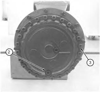
Illustration 5 g01057340
4. Slide final drive (4) slightly outward. Attach Tooling (C) and a suitable lifting device onto final drive (4). The weight of final drive (4) is approximately 52 kg (115 lb). Remove Tooling (A) and Tooling (B). Remove final drive (4) .
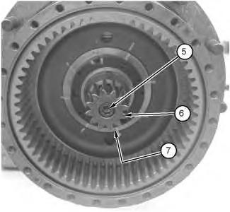
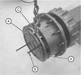
Illustration 6 g01057341
5. Remove bolt (5). Remove sun gear (6) and sleeve (7) .
Illustration 7
6. Remove axle shaft (8) .
g01057342
7. Repeat this procedure for the opposite side.
Copyright 1993 - 2020 Caterpillar Inc.
All Rights Reserved. Private Network For SIS Licensees.
Thu Nov 26 13:43:57 UTC+0800 2020
Shutdown SIS
Previous Screen
Product: EXCAVATOR
Model: M325D MH EXCAVATOR EDF
Configuration: M325D Material Handler EDF00001-01999 (MACHINE) POWERED BY C-7 Engine
Disassembly and Assembly
M325D Material Handler Power Train
Axle Shaft - Install - Steering Axle
SMCS - 3259-012; 3278-012; 3282-012-JF
Installation Procedure Table 1
Required Tools
Media Number -RENR9720-00 Publication Date -01/05/2009 Date Updated -14/05/2009 i05901867
Tool Part Number Part Description Qty C 138-7575 Link Bracket 1 D 1U-9200 Lever Puller Hoist 1 F 1P-1861 Retaining Ring Pliers 1 J 1P-0510 Driver Gp 1 K - Loctite High Flex Form a Gasket 1 L - Loctite 263 1
1. Lower the temperature of bushing (22) . Use Tooling (J) in order to install bushing (22) . Use Tooling (J) in order to install seal (21) . Repeat for the seal and the bushing in hub assembly (13) . Hub assembly (13) is not shown.
2. Use a suitable press and install U-joints (20) .
3. Install plugs (19) . Use Tooling (F) in order to install retaining rings (18) .
Illustration 1 g01136750
Illustration 2 g01136749
Illustration 3 g01136723
4. Attach a suitable lifting device onto axle shaft (17) . The weight of axle shaft (17) is approximately 34 kg (75 lb). Install axle shaft (17) .
5. Lower the temperature of bushing (16) . Use Tooling (J) and install bushing (16) .
Illustration 4 g01136735
Illustration 5
g01136720
Illustration 6
g01136716
6. Position shim (15) .
7. Attach Tooling (D) and a suitable lifting device onto hub assembly (13) . The weight of hub assembly (13) is approximately 246 kg (542 lb). Install hub assembly (13) . Lower the temperature of pins (14) . Install pins (14) .
8. Apply Tooling (K) to the contact surface of cover (12) . Install cover (12) . Apply Tooling (L) to the threads of bolts (11) . Install bolts (11) . Tighten bolts (11) to a torque of 310 N·m (229 lb ft).
Illustration 7
g01136846
Illustration 8
g01136692
9. Attach a suitable lifting device onto lever (9) . Position lever (9) and install bolts (10) .
10. Install sleeve (8) and sun gear (7) . Apply Tooling (L) to the threads of bolt (6) . Install bolt (6) . Tighten bolt (6) to a torque of 310 N·m (229 lb ft).
Illustration 9
g01136690
Illustration 10
g01136688
Illustration 11
g01136687
Note: Check the O-ring seal for wear or for damage. If necessary, replace the O-ring seal.
11. Install O-ring seal (5) onto final drive (4) . Attach Tooling (C) and a suitable lifting device onto final drive (4) . The weight of final drive (4) is approximately 52 kg (115 lb).
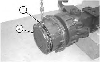
Illustration 12 g01136863
12. Install final drive (4) .
Illustration 13 g01136680
13. Apply Tooling (L) to the threads of bolts (3) . Install bolts (3) . Tighten bolts (3) to a torque of 72 N·m (53 lb ft). Install plug (2) .
g01136679
14. Install plug (1) .
15. Fill the axle and the final drive with oil. Refer to Operation and Maintenance Manual, "Axle Oil - Change"and Operation and Maintenance Manual, "Final Drive Oil - Change". Refer to Operation and Maintenance Manual, "Capacities (Refill)".
Copyright 1993 - 2020 Caterpillar Inc.
All Rights Reserved. Private Network For SIS Licensees.
Thu Nov 26 13:44:53 UTC+0800 2020
Illustration 14
Shutdown SIS
Previous Screen
Product: EXCAVATOR
Model: M325D MH EXCAVATOR EDF
Configuration: M325D Material Handler EDF00001-01999 (MACHINE) POWERED BY C-7 Engine
Disassembly and Assembly
M325D Material Handler Power Train
Axle Shaft - Install - Fixed Axle
SMCS - 3259-012; 3278-012; 3282-012-JF
Installation Procedure Table 1
Required Tools
Media Number -RENR9720-00 Publication Date -01/05/2009 Date Updated -14/05/2009 i02063523
Tool Part Number Part Description Qty A 8T-3666 Bolt 2 C 138-7575 Link Bracket 1 D - Loctite 262 1
1. Install axle shaft (8) .
2. Install sleeve (7) and sun gear (6). Apply Tooling (D) to the threads of bolt (5). Install bolt (5) and tighten bolt (5) to a torque of 310 N·m (229 ft).
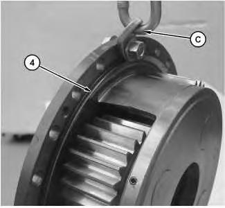 Illustration 1 g01057342
Illustration 2 g01057341
Illustration 3 g01057508
Illustration 1 g01057342
Illustration 2 g01057341
Illustration 3 g01057508
Suggest:
If the above button click is invalid.
Please download this document first, and then click the above link to download the complete manual.
Thank you so much for reading

3. Attach Tooling (C) and a suitable lifting device onto final drive (4). The weight of final drive (4) is approximately 52 kg (115 lb).
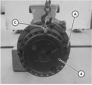
Illustration 4
g01057509
4. Position final drive (4) on the axle. Install Tooling (A). Remove Tooling (C). Slide final drive (4) in all the way. Remove Tooling (A) .
Illustration 5
g01057338
5. Apply Tooling (D) to the threads of bolts (3). Install bolts (3). Tighten bolts (3) to a torque of 200 N·m (148 lb ft). Install plug (2) .