
Previous Screen
Product: EXCAVATOR
Model: M312 EXCAVATOR 6TL
Configuration: M312 Excavator 6TL00001-00409 (MACHINE) POWERED BY 3054 Engine
Disassembly and Assembly
M312 and M315 Excavators Machine Systems Supplement
Swing Drive - Disassemble
SMCS - 5459-015
Disassembly Procedure
Table 1 Required Tools
Start By:
a. Remove the swing drive. Refer to Disassembly and Assembly, "Swing Drive - Remove".
NOTICE
Care must be taken to ensure that fluids are contained during performance of inspection, maintenance, testing, adjusting, and repair of the product. Be prepared to collect the fluid with suitable containers before opening any compartment or disassembling any component containing fluids.
Refer to Special Publication, NENG2500, "Dealer Service Tool Catalog" for tools and supplies suitable to collect and contain fluids on Cat products.
Dispose of all fluids according to local regulations and mandates.
Note: Cleanliness is an important factor. Before the disassembly procedure, the exterior of the component should be thoroughly cleaned. This will help to prevent contaminants from entering the internal mechanism.
Illustration
1
g01027113
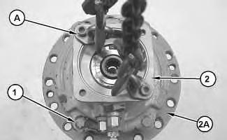
1. Attach Tooling (A) and a suitable lifting device to swing brake assembly (2). The weight of swing brake assembly (2) is approximately 75 kg (165 lb).
2. Note the orientation of swing brake assembly (2) for assembly purposes.
3. Remove bolts (1). Remove swing brake assembly (2).
Personal injury can result from being struck by parts propelled by a released spring force.
Make sure to wear all necessary protective equipment.
Follow the recommended procedure and use all recommended tooling to release the spring force.
4. Position swing brake assembly (2) in a suitable press.
5. Use Tooling (B) and a suitable press to relieve tension on retaining ring (3). Use Tooling (C) to remove retaining ring (3).
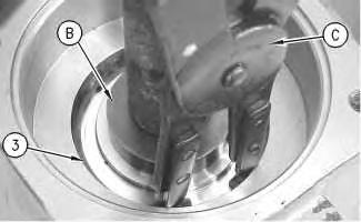
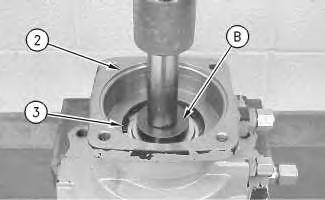 Illustration 2
g00906311
Illustration 3
g00909003
Illustration 2
g00906311
Illustration 3
g00909003
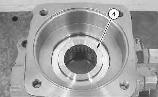
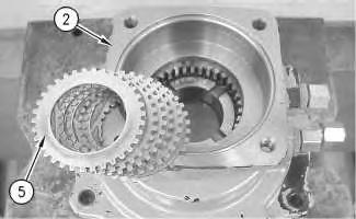
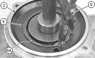 Illustration 4
g00906313
6. Remove plate (4).
Illustration 5
g00906314
7. Remove the discs and plates (5) from swing brake assembly (2).
Illustration 6
g00909004
Illustration 4
g00906313
6. Remove plate (4).
Illustration 5
g00906314
7. Remove the discs and plates (5) from swing brake assembly (2).
Illustration 6
g00909004
Personal injury can result from being struck by parts propelled by a released spring force.
Make sure to wear all necessary protective equipment.
Follow the recommended procedure and use all recommended tooling to release the spring force.
8. Reposition swing brake assembly (2), as shown.
9. Use Tooling (K) and a suitable press to relieve tension on retaining ring (6). Use Tooling (D) to remove retaining ring (6) and the shim. Remove spring (6A) from swing brake assembly (2).
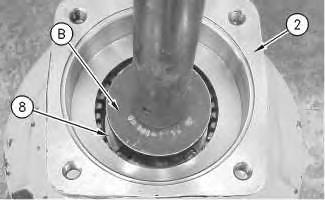
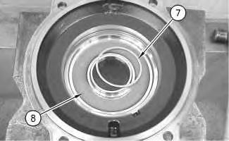 Illustration 7
g00909008
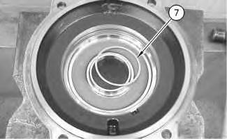
10. If equipped, remove ring (7) from piston (8).
Illustration 8
g00906320
11. Use Tooling (B) and a suitable press to remove piston (8) from swing brake assembly (2).
Illustration 7
g00909008
10. If equipped, remove ring (7) from piston (8).
Illustration 8
g00906320
11. Use Tooling (B) and a suitable press to remove piston (8) from swing brake assembly (2).
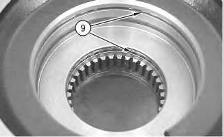
Illustration 9
12. Remove seals (9) from the swing brake assembly.
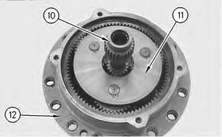
Illustration 10
13. Remove shaft (10) and top carrier (11) from shaft drive (12).
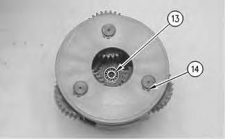
Illustration 11
14. Remove bearing (13). Use Tooling (F) to remove retaining ring (14).
 g00906322
g00906324
g00906325
g00906322
g00906324
g00906325
Illustration 12
15. Remove pins (19), gears (15), washers (18) and (17), and needle bearings (16).
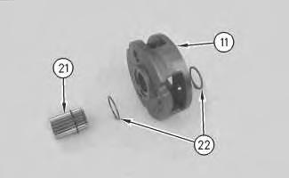
Illustration 13
16. Use Tooling (E) to remove retaining ring (20) from top carrier (11).
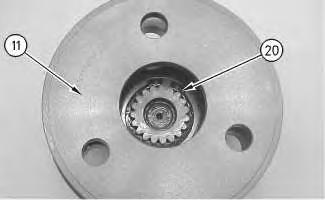
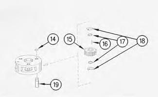
Illustration 14
17. Remove sun gear (21) and washers (22) from top carrier (11).
g00906327 g00906329 g00906330Illustration 15
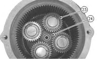
18. Use Tooling (E) to remove retaining rings (23) and bearings (24).
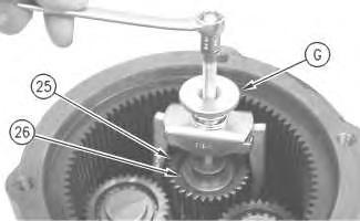
Illustration 16
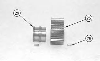
19. Use Tooling (G) to remove gear (25).
20. Remove needle bearings (26).
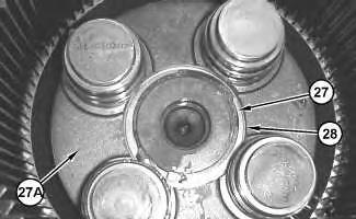
Illustration 17
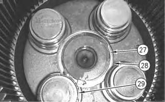
21. Use Tooling (H) to remove retaining ring (27). Remove shim (28) and carrier (27A).
g00906331 g00909009 g0102654922. Use Tooling (G) to remove bearing race (29).
Illustration 20
23. Position swing drive housing (33A) and pinion (33) on a suitable press.
24. Use Tooling (J) to remove nut (30). Remove ring (31) and nut (32).
Note: Support the underside of pinion (33) before the following Step is performed.
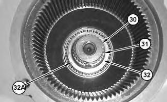
25. Use a suitable press to remove pinion (33) and bearing cone (32A).
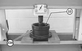
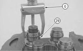 Illustration 18
g00909011
Illustration 19
g01026558
g01026627
Illustration 18
g00909011
Illustration 19
g01026558
g01026627
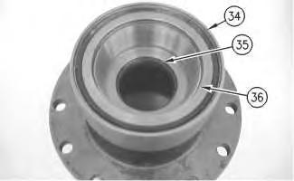
Illustration 21
g00906881
26. Remove seal (34) and lip seal (35). Use Tooling (K) to remove bearing cup (36).
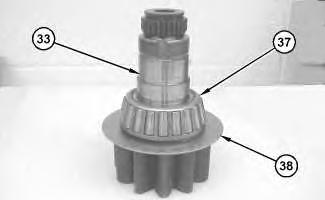
Illustration 22
g01026650
27. Remove bearing cone (37) and washer (38) from pinion (33).
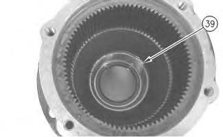
Illustration 23
g00906883
28. Use Tooling (K) to remove bearing cup (39).
Previous Screen
Product: EXCAVATOR
Model: M312 EXCAVATOR 6TL
Configuration: M312 Excavator 6TL00001-00409 (MACHINE) POWERED BY 3054 Engine
Disassembly and Assembly
M312 and M315 Excavators Machine Systems Supplement
Swing Drive - Assemble
SMCS - 5459-016
Assembly Procedure
(2) Used on the part number 152-7372 Swing Drive Gp
(3) Used on the part number 152-7375 Swing Drive Gp
Note: Replace all O-ring seals and all gaskets. Apply a light film of "10W" oil to all components before assembly.
Note: Cleanliness is an important factor. Before assembly, all parts should be thoroughly cleaned in cleaning fluid. Allow the parts to air dry. Wiping cloths or rags should not be used to dry parts. Lint may be deposited on the parts which may cause later trouble. Inspect all parts. If any parts are worn or damaged, use new parts for replacement.
Illustration 1
g01027198
1. Lower the temperature of bearing cup (39). Use Tooling (K) to install bearing cup (39) in swing drive housing (33A).
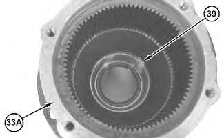
Illustration 2
g00906881
2. Lower the temperature of bearing cup (36). Use Tooling (K) to install bearing cup (36).
3. Use Tooling (B) to install lip seal (35). Install seal (34). Install tooling (L) to seal (34).
Illustration 3
4. Raise the temperature of bearing cone (37). Install washer (38) and bearing cone (37) on pinion (33).
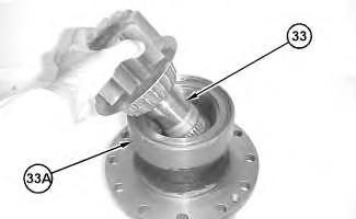
Illustration 4
Illustration 5
5. The following steps should be used on machines that are equipped with the part number 152 -7372 Swing Drive Gp.
a. Apply 80 grams of Tooling (L) to the bearing cone on pinion (33). Install pinion (33) in swing drive housing (33A).
g01026650
g01027078
g01026558
b. Raise the temperature of bearing cone (32A). Install bearing cone (32A).
c. Install nut (32). Use Tooling (J) in order to tighten nut (32) until a slight increase in rolling torque is obtained. Loosen nut (32) by approximately 60 degrees. Strike pinion (33) with a soft hammer in order to release the bearing preload.
d. Determine the initial rolling torque of pinion (33). The specified rolling torque is 8 N·m (71 lb in) to 15 N·m (133 lb in). Record this value as Rolling Torque (Y).
e. As you tighten nut (32) rotate swing drive housing (33A) in order to ensure that the bearings are seated properly. Use Tooling (J) in order to tighten nut (32) to a torque of 300 N·m (221 lb ft). Loosen nut (32) by 30 degrees to 60 degrees.
f. Install ring (31).
g. Install nut (30). Use Tooling (J) in order to tighten nut (30) to a torque of 1000 ± 100 N·m (738 ± 74 lb ft).
h. Determine the rolling torque of pinion (33). The specified rolling torque is Rolling Torque (Y) plus 3 N·m (27 lb in) to 9 N·m (80 lb in).
6. The following steps should be used on machines that are equipped with the part number 152 -7375 Swing Drive Gp.
a. Apply 80 grams of Tooling (L) to the bearing cone on pinion (33). Install pinion (33) in swing drive housing (33A).
b. Raise the temperature of bearing cone (32A). Install bearing cone (32A).
c. Install nut (32). Use Tooling (J) in order to tighten nut (32) until a slight increase in rolling torque is obtained. Loosen nut (32) by approximately 60 degrees. Strike pinion (33) with a soft hammer in order to release the bearing preload.
d. Determine the initial rolling torque of pinion (33). The specified rolling torque is 6 N·m (53 lb in) to 8 N·m (71 lb in). Record this value as Rolling Torque (Y).
e. As you tighten nut (32) rotate swing drive housing (33A) in order to ensure that the bearings are seated properly. Use Tooling (J) in order to tighten nut (32) to a torque of 250 ± 50 N·m (184 ± 37 lb ft). Loosen nut (32) by 15 degrees to 30 degrees.
f. Install ring (31).
g. Install nut (30). Use Tooling (J) in order to tighten nut (30) to a torque of 700 ± 50 N·m (516 ± 37 lb ft).
h. Determine the rolling torque of pinion (33). The specified rolling torque is Rolling Torque (Y) plus 2 N·m (18 lb in) to 5 N·m (44 lb in).
7. Install carrier (27A).
8. Install shim (28). Use Tooling (H) to install retaining ring (27).
9. Raise temperature of bearing race (29). Install bearing race (29) and needle bearings (26).
10. Apply Tooling (L) to the rollers. Install the rollers on bearing race (29). Install gears (25) over bearing race (29) and the rollers.
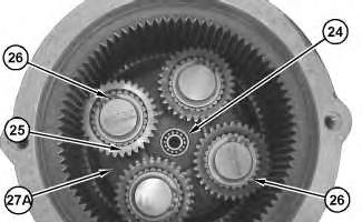 Illustration 6
g00907108
Illustration 7
g00907110
Illustration 8
g01027098
Illustration 6
g00907108
Illustration 7
g00907110
Illustration 8
g01027098
11. Install retaining ring (23) and bearing (24).
Illustration 9 g00906330
12. Install washers (22) and sun gear (21) onto top carrier (11).
Illustration 10 g00906329
13. Use Tooling (E) to install retaining ring (20) onto top carrier (11).
Illustration 11 g00906327
14. Install needle bearings (16), washers (17) and (18), gears (15), and pins (19).
Illustration 12
Illustration 14
g00906325
15. Use Tooling (F) to install retaining ring (14). Install bearing (13).
Illustration 13
g00906324
16. Install top carrier (11) and shaft (10) in shaft drive (12).
g00906322
17. Install seals (9) in the swing brake assembly.
18. Use Tooling (B) to install piston (8) in swing brake assembly (2).
19. If equipped, install ring (7).
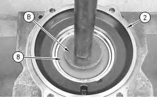 Illustration 15
g00909400
Illustration 16
g00906319
Illustration 17
g00909004
Illustration 15
g00909400
Illustration 16
g00906319
Illustration 17
g00909004
Improper assembly of parts that are spring loaded can cause bodily injury.
To prevent possible injury, follow the established assembly procedure and wear protective equipment.
20. Install spring (6A) and the shim.
21. Use Tooling (K) and a suitable press in order to compress spring (6A). Use Tooling (D) in order to install retaining ring (6). Rotate the opening in retaining ring (6) by approximately 180 degrees from the notch in swing brake assembly (2).
Illustration 18
22. Install discs and plates (5) into swing brake assembly (2).
Illustration 19
23. Install plate (4).
g00906314 g00906313Improper assembly of parts that are spring loaded can cause bodily injury.
To prevent possible injury, follow the established assembly procedure and wear protective equipment.
24. Use Tooling (B) and a suitable press in order to compress the spring. Use Tooling (C) to install retaining ring (3).
Illustration 20
g00906311
Illustration 21
g00909003
Illustration 22
g01822733
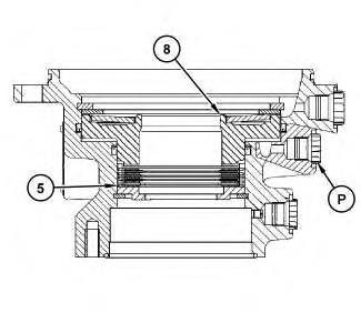
25. Position Tooling (M) in order to measure the travel of piston (8). Connect Tooling (N) to Port (P). Use Tooling (N) in order to apply 3000 kPa (435 psi) at Port (P). Record the measured travel of piston (8) as Dimension (X).
a. The recorded Dimension (X) should be 1.2 mm (0.05 inch) to 1.4 mm (0.06 inch) on machines that are equipped with the part number 152-7372 Swing Drive Gp.
b. The recorded Dimension (X) should be 1.1 mm (0.04 inch) to 1.3 mm (0.05 inch) on machines that are equipped with the part number 152-7375 Swing Drive Gp.
Note: Outer plate (5) is available in different thicknesses. Use the correct thickness of plate (5) in order to obtain the correct Dimension (X).
Illustration 23
g01027113
26. Install Tooling (A) and a suitable lifting device to swing brake assembly (2). The weight of swing brake assembly (2) is approximately 75 kg (165 lb).
27. Position swing brake assembly (2) in swing brake housing (2A).
28. Install bolts (1).
End By:
a. Install the swing drive. Refer to Disassembly and Assembly, "Swing Drive - Install".
Previous Screen
Product: EXCAVATOR
Model: M312 EXCAVATOR 6TL
Configuration: M312 Excavator 6TL00001-00409 (MACHINE) POWERED BY 3054 Engine
Disassembly and Assembly
M312 and M315 Excavators Machine Systems Supplement
Swing Drive - Install
SMCS - 5459-012
Installation Procedure Table 1 Required Tools
Tool Part Number Part Description Qty
(A) 138-7574 Link Bracket 2
NOTICE
Care must be taken to ensure that fluids are contained during performance of inspection, maintenance, testing, adjusting and repair of the product. Be prepared to collect the fluid with suitable containers before opening any compartment or disassembling any component containing fluids.
Refer to Special Publication, NENG2500, "Caterpillar Tools and Shop Products Guide" for tools and supplies suitable to collect and contain fluids on Caterpillar products.
Dispose of all fluids according to local regulations and mandates.
g00699322
1. Install tooling (A). Attach an appropriate lifting device to tooling (A) and install the swing drive. The weight of the swing drive is approximately 52 kg (115 lb).
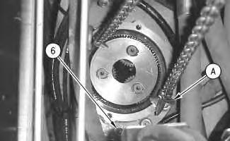
2. Install bolts (6) .
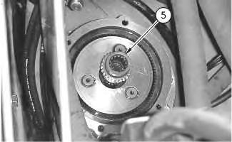
g00699266
3. Install shaft (5) into the swing drive.
Illustration 1 Illustration 2Suggest:
If the above button click is invalid.
Please download this document first, and then click the above link to download the complete manual.
Thank you so much for reading

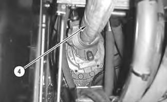
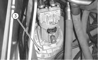
4. Attach lifting strap (4) and a hoist to the swing motor.
5. Install the swing motor and swing brake valve as a unit. The weight of the swing motor and swing brake valve is approximately 25 kg (55 lb).
6. Install four bolts (3) into the swing brake valve.
7. Connect hose assemblies (2) to the swing motor.
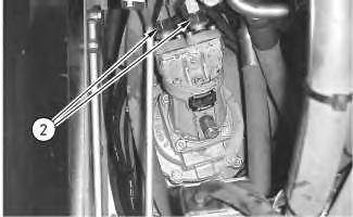 Illustration 3 g00698749
Illustration 4 g00698645
Illustration 5 g00697670
Illustration 3 g00698749
Illustration 4 g00698645
Illustration 5 g00697670