Previous Screen
Product: EXCAVATOR
Model: M312 EXCAVATOR 6TL
Configuration: M312 Excavator 6TL00410-UP (MACHINE) POWERED BY 3054 Engine
Disassembly and Assembly
M312 and M315 Excavators Power Train Supplement
Travel Motor - Disassemble
SMCS - 4351-015
S/N - 6TL1140-UP
S/N - 7ML1917-UP
Disassembly
Procedure Table 1
Required Tools
(C)
Start By:
A. Remove the travel motor. Refer to Disassembly and Assembly, "Travel Motor - Remove" in this manual.
NOTICE
Care must be taken to ensure that fluids are contained during performance of inspection, maintenance, testing, adjusting and repair of the product. Be prepared to collect the fluid with suitable containers before opening any compartment or disassembling any component containing fluids.
Refer to Special Publication, NENG2500, "Caterpillar Tools and Shop Products Guide" for tools and supplies suitable to collect and contain fluids on Caterpillar products.
Dispose of all fluids according to local regulations and mandates.
Note: Cleanliness is an important factor. Before the disassembly procedure, the exterior of the component should be thoroughly cleaned. This will help to prevent dirt from entering the internal mechanism.
Illustration 1
g00715031
1. Remove two drain plugs (2) from housing (1). Drain the oil from the travel motor into a suitable container for storage or disposal.
Illustration 2
g00715021
2. Mark brake valve (3) for reassembly purposes. Remove socket head bolts (4), bolts (5), covers (6) and gaskets (7) .
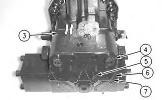
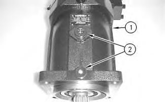
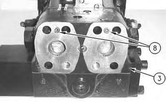
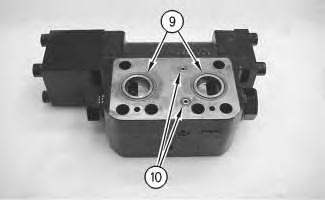
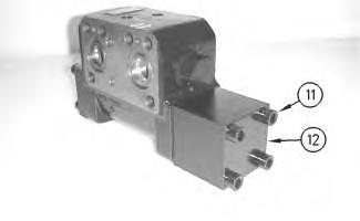 Illustration 3 g00715053
3. Remove two socket head bolts (8). Remove brake valve (3) .
Illustration 4 g00715270
4. Remove two large O-ring seals (9) and two small O-ring seals (10) .
Illustration 5
g00715056
Illustration 3 g00715053
3. Remove two socket head bolts (8). Remove brake valve (3) .
Illustration 4 g00715270
4. Remove two large O-ring seals (9) and two small O-ring seals (10) .
Illustration 5
g00715056
 5. Remove four bolts (11). Remove cover (12) .
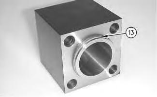
Illustration 6 g00715065
6. Remove O-ring seal (13) .
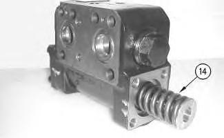
Illustration 7 g00715098
7. Remove piston assembly (14) from the brake valve.
5. Remove four bolts (11). Remove cover (12) .
Illustration 6 g00715065
6. Remove O-ring seal (13) .
Illustration 7 g00715098
7. Remove piston assembly (14) from the brake valve.
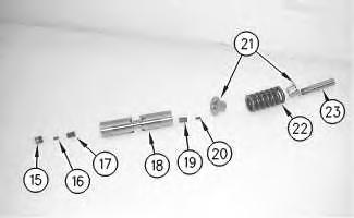
Illustration 8 g00715103
8. Remove screw plug (15), pin (16) and retainer (17) from spool (18). Remove screw (23), spring retainers (21), spring (22), pin (20) and retainer (19) from spool (18) .
Illustration 9 g00715208
9. Remove four socket head bolts (24). Remove cover (25) .
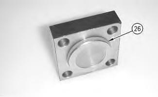
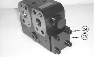
Illustration 10 g00715214
10. Remove O-ring seal (26) .
Illustration 11
g00715318
11. Remove valve (27), O-ring seal (28), spring (29) and plunger (30). Remove lock (31), spring (32) and plunger (33) .
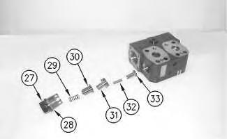
12. Repeat Step 11 on the other side.
Illustration 12
g00715335
13. Remove plug (34) and the O-ring seal. Plug (35) and the O-ring seal. Plug (36) and the Oring seal.
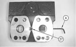
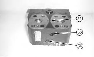
Illustration 13
g00715343
14. Use Tooling (A) in order to remove valve (37) .
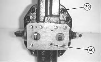
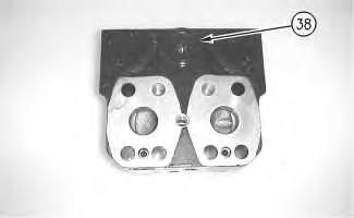
Illustration 14
15. Remove plug (38) and the O-ring seal.
g00715351
Illustration 15
g00715362
16. Remove eight bolts (39). Remove O-ring seal (40) .
Illustration 16
17. Remove port plate (41) .
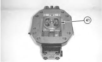
g00715373
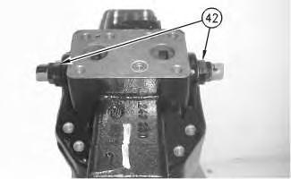
Illustration 17
g00715385
18. Remove the plastic caps. Remove valve assemblies (42). Mark the two covers for reassembly purposes.
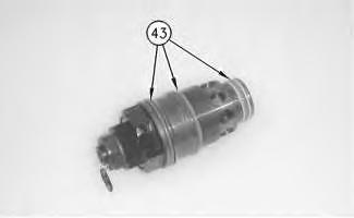
Illustration 18
g00715795
19. Remove three O-ring seals (43) from both valves.
20. Remove plugs (43) and the O-ring seals.
21. Remove bolts (44) and cover (45) .
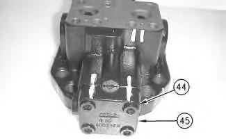
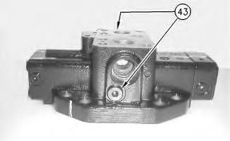 Illustration 19
g00716288
Illustration 20
g00716310
Illustration 19
g00716288
Illustration 20
g00716310
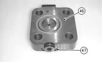
Illustration 21
g00716320
22. Remove large O-ring seal (46). Remove plug (47) and the O-ring seal.
Personal injury can result from parts and/or covers under spring pressure.
Spring force will be released when covers are removed. Be prepared to hold spring loaded covers as the bolts are loosened.
Illustration 22
Note: Cover (49) is under spring pressure.
g00716327
23. Carefully remove bolts (48) and cover (49). Remove plastic cap (50) .
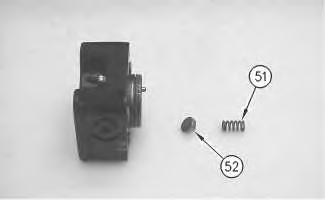
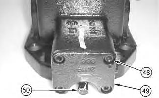
Illustration 23
24. Remove spring (51) and bushing (52) .
g00716401
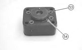
Illustration 24
g00716407
25. Remove four small O-ring seals (53) and one large O-ring seal (54) .
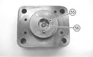
Illustration 25
g00716413
26. Remove retaining ring (55) and valve assembly (56) .
Illustration 26
27. Remove clip (57). Remove stem (58) from spool (59) .
Illustration 27
28. Remove plug (60) and the O-ring seal.
Illustration 28
Note: Record distance (X) from the locknut to the end of the screw for installation purposes.
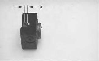
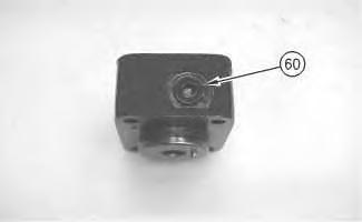
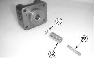
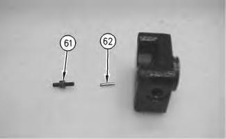
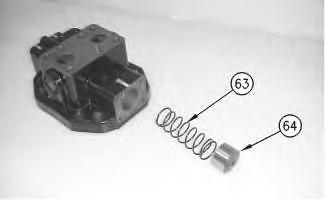
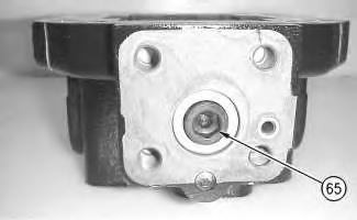 Illustration 29
g00716436
29. Remove screw (61) and dowel (62) .
Illustration 30
g00716440
30. Remove spring (63) and cap (64) .
Illustration 29
g00716436
29. Remove screw (61) and dowel (62) .
Illustration 30
g00716440
30. Remove spring (63) and cap (64) .
Illustration 31 g00716557
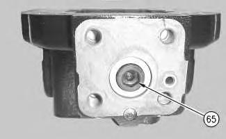
31. Remove screw (65) in order to remove the piston.
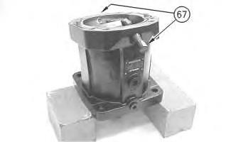
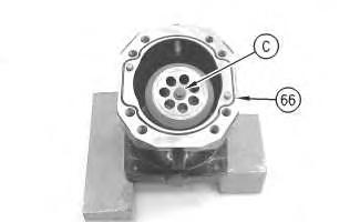
Illustration 32 g00716567
32. Install Tooling (C). Remove seal (66) .
Illustration 33 g00716576
33. Remove plastic caps (67) .
g00716586
Note: Record the distance from the locknut to the end of the set screw for installation purposes.
34. Remove locknuts (68) and screws (69) .
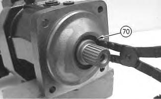
g00716593
35. Use the appropriate retaining ring pliers to remove retaining ring (70) .
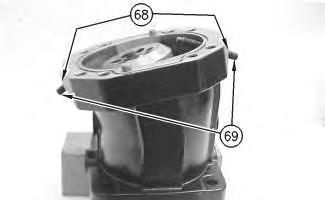 Illustration 34
Illustration 35
Illustration 34
Illustration 35
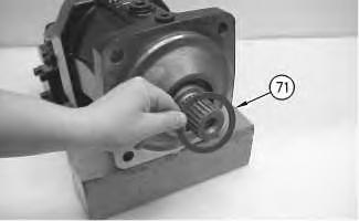
Illustration 36
36. Remove shim (71) .
g00716597
Illustration 37 g00716600
37. Use Tooling (B) in order to remove seal (72) .
Illustration 38
g00716601
38. Use a suitable press in order to remove rotator assembly (73) .
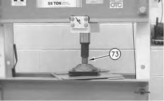
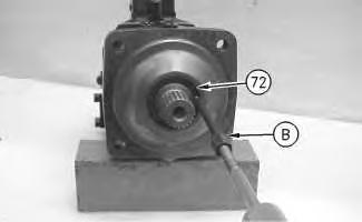
Illustration 39 g00716605
39. Remove Tooling (C) from barrel (74) .
Illustration 40 g00716607
40. Remove screws (75) from retainer (76). Remove pistons (77) and center pin (78) .
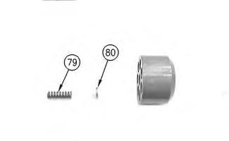
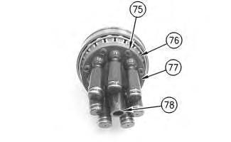
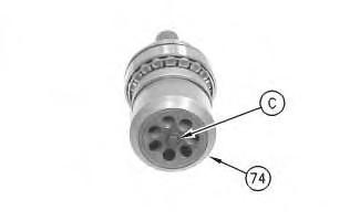
Illustration 41 g00716610
41. Remove spring (79) and shim (80) .
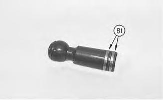
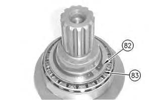
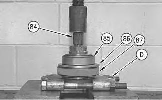 Illustration 42 g00716621
42. Remove rings (81) .
Illustration 43 g00716696
43. Remove retaining ring (82) and shim (83) .
Illustration 42 g00716621
42. Remove rings (81) .
Illustration 43 g00716696
43. Remove retaining ring (82) and shim (83) .
44. Place the rotor assembly in a suitable press. Use Tooling (D) in order to press shaft (84) from bearing (85), shim (86) and bearing (87) .
Copyright 1993 - 2020 Caterpillar Inc. All Rights Reserved. Private Network For SIS Licensees.
Previous Screen
Product: EXCAVATOR
Model: M312 EXCAVATOR 6TL
Configuration: M312 Excavator 6TL00410-UP (MACHINE) POWERED BY 3054 Engine
Disassembly and Assembly
M312 and M315 Excavators Power Train Supplement
Travel Motor - Assemble
SMCS - 4351-016
S/N - 6TL1140-UP
S/N - 7ML1917-UP
Assembly Procedure
Required Tools
(A)
(C)
(E) 149-4935 Measuring Tool 1
(F) 1P-0510 Driver Group 1
Note: Replace all O-ring seals and gaskets. Apply a light film of hydraulic oil to all components before assembly.
Note: Cleanliness is an important factor. Before assembly, all parts should be thoroughly cleaned in cleaning fluid. Allow the parts to air dry. Wiping cloths or rags should not be used to dry parts. Lint may be deposited on the parts which may cause later trouble. Inspect all parts. If any parts are worn or damaged, use new parts for replacement.
1. Install screw (65) in order to secure the piston.
2. Install spring (63) and cap (64) .
Illustration 1 g00717509
Illustration 2 g00717517
Illustration 3 g00716428
Note: Use recorded distance (X) from the locknut to the end of the screw for installation purposes.
Illustration 4 g00716436
Illustration 5 g00716419
3. Install screw (61) and dowel (62) . 4. Install plug (60) and the new O-ring seal.
Illustration 6 g00716533
5. Install stem (58) into spool (59). Install clip (57).
Illustration 7 g00716413
6. Install valve assembly (56) and retaining ring (55) .
Illustration 8 g00716407
7. Install four new small O-ring seals (53) and one new large O-ring seal (54) .
Illustration 9 g00716401
8. Install spring (51) and bushing (52) .
Illustration 10 g00716327
9. Install cover (49) and bolts (48). Tighten the bolts to a torque of 35 N·m (26 lb ft). Install plastic cap (50) .
Suggest:
If the above button click is invalid.
Please download this document first, and then click the above link to download the complete manual.
Thank you so much for reading

Illustration 11
g00716320
10. Install new large O-ring seal (46). Install plug (47) and the new O-ring seal.
Illustration 12
g00716310
11. Install cover (45) and bolts (44). Tighten the bolts to a torque of 120 N·m (88 lb ft).
Illustration 13
g00716288
12. Install plugs (43) and the new O-ring seals.