Service
Shutdown SIS
Previous Screen
Product: EXCAVATOR
Model: EL200B EXCAVATOR 7DF
Configuration: E200B, EL200B TRACK-TYPE EXCAVATORS 7DF00001-UP (MACHINE) POWERED BY 3116 ENGINE
Disassembly and Assembly
446 and 446B Backhoe Loaders, Lexion 450 Combine, 3114 and 3116 Engines, IT18F Integrated Toolcarrier, D6M Track-Type Tractor and 928F, 950F and 950G
Wheel Loaders
Engine Oil Pump - Remove
SMCS - 1304-011
Removal Procedure
Start By:
a. Remove the engine oil pan. Refer to Disassembly and Assembly, "Engine Oil Pan - Remove and Install".
NOTICE
Keep all parts clean from contaminants.
Contaminants may cause rapid wear and shortened component life.
NOTICE
Care must be taken to ensure that fluids are contained during performance of inspection, maintenance, testing, adjusting, and repair of the product. Be prepared to collect the fluid with suitable containers before opening any compartment or disassembling any component containing fluids.
Refer to Special Publication, NENG2500, "Dealer Service Tool Catalog" for tools and supplies suitable to collect and contain fluids on Cat products.
Dispose of all fluids according to local regulations and mandates.
Note: For information on the reusability of the engine oil pump, refer to Guideline For Reusable Parts And Salvage Operations, SEBF8167, "Reconditioning Procedures 3114 and 3116 Engines".
1. Remove bolts (1) and bolt (2).
2. Remove engine oil pump (3).
3. Remove the O-ring seal that is located between the cylinder block and the outlet elbow.
Copyright 1993 - 2019 Caterpillar Inc. All Rights Reserved. Private Network For SIS Licensees.
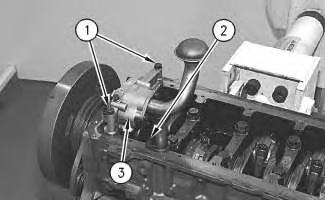 Illustration 1
g00894501
Illustration 1
g00894501
Shutdown SIS
Previous Screen
Product: EXCAVATOR
Model: EL200B EXCAVATOR 7DF
Configuration: E200B, EL200B TRACK-TYPE EXCAVATORS 7DF00001-UP (MACHINE) POWERED BY 3116 ENGINE
Disassembly and Assembly
446 and 446B Backhoe Loaders, Lexion 450 Combine, 3114 and 3116 Engines, IT18F Integrated Toolcarrier, D6M Track-Type Tractor and 928F, 950F and 950G
Wheel Loaders
Engine Oil Pump - Disassemble
SMCS - 1304-015
Disassembly Procedure
Table 1
Required Tools
Tool
A 1P-0510 Driver Gp 1
B 1P-2320 Combination Puller 1
Start By:
a. Remove the engine oil pump. Refer to Disassembly and Assembly, "Engine Oil PumpRemove".
NOTICE
Keep all parts clean from contaminants.
Contaminants may cause rapid wear and shortened component life.
Care must be taken to ensure that fluids are contained during performance of inspection, maintenance, testing, adjusting, and repair of the product. Be prepared to collect the fluid with suitable containers before opening any compartment or disassembling any component containing fluids.
Refer to Special Publication, NENG2500, "Dealer Service Tool Catalog" for tools and supplies suitable to collect and contain fluids on Cat products.
Dispose of all fluids according to local regulations and mandates.
Note: For information on the reusability of the engine oil pump, refer to Guideline For Reusable Parts And Salvage Operations, SEBF8167, "Reconditioning Procedures 3114 and 3116 Engines".
g00614664
g00614677
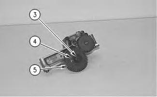
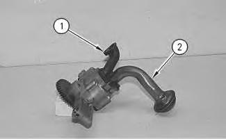
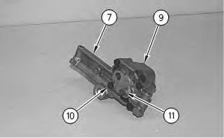
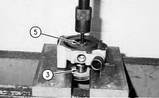
Illustration 1 1. Remove the bolts from tube assembly for the pickup of oil (2), and the gasket from the engine oil pump. Remove the bolt and outlet elbow (1) from the engine oil pump. Illustration 2 2. Remove bolt (3), washer (4), and idler gear (5) from the engine oil pump.3. Use Tooling (A) and a suitable press in order to remove the bearing from idler gear (5).
4. Remove shaft (6) of engine oil pump from oil pump body assembly (7).
5. Use Tooling (B) to remove drive gear (8).
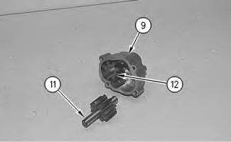
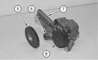 Illustration 3
g00614683
Illustration 4
g00614689
6. Remove bolts (10). Separate oil pump body (9) from oil pump body assembly (7).
Illustration 5
g00614694
Illustration 3
g00614683
Illustration 4
g00614689
6. Remove bolts (10). Separate oil pump body (9) from oil pump body assembly (7).
Illustration 5
g00614694
Before removing the drive shaft from the pump housing, be sure that no burrs exist on the drive shaft. If the drive shaft has burrs on it, the bores in the pump housing may be scratched.
7. Remove shaft assembly (11) and shaft assembly (12) from oil pump body (9).
Personal injury can result from parts and/or covers under spring pressure.
Spring force will be released when covers are removed.
Be prepared to hold spring loaded covers as the bolts are loosened.
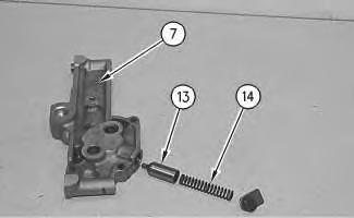
8. Remove the following items from oil pump body assembly (7): the bolt and the washer, spring (14) and oil pressure relief plunger (13)
Copyright 1993 - 2019 Caterpillar Inc.
All Rights Reserved.
Private Network For SIS Licensees.
Fri Sep 13 22:09:27 UTC+0800 2019
Shutdown SIS
Previous Screen
Product: EXCAVATOR
Model: EL200B EXCAVATOR 7DF
Configuration: E200B, EL200B TRACK-TYPE EXCAVATORS 7DF00001-UP (MACHINE) POWERED BY 3116 ENGINE
Disassembly and Assembly
446 and 446B Backhoe Loaders, Lexion 450 Combine, 3114 and 3116 Engines, IT18F Integrated Toolcarrier, D6M Track-Type Tractor and 928F, 950F and 950G
Wheel Loaders
Engine Oil Pump - Assemble
SMCS - 1304-016
Assembly Procedure
Table 1
Required Tools
Keep all parts clean from contaminants.
Contaminants may cause rapid wear and shortened component life.
Note: For information on the reusability of the engine oil pump, refer to Guideline For Reusable Parts And Salvage Operations, SEBF8167, "Reconditioning Procedures 3114 and 3116 Engines".
1. Ensure that all of the parts of the engine oil pump are thoroughly clean prior to assembly.
Note: Lubricate all internal parts of the engine oil pump with clean engine oil.
Improper assembly of parts that are spring loaded can cause bodily injury.
To prevent possible injury, follow the established assembly procedure and wear protective equipment.
Illustration 1
g00824021
2. Install oil pressure relief plunger (13) and spring (14) in oil pump body assembly (7). Install the washer and the bolt.
Illustration 2
g00614694
g00614689
3. Install shaft assembly (12) in oil pump body (9).
4. Install shaft assembly (11) in oil pump body (9).
5. Position oil pump body (9) on oil pump body assembly (7) and install bolts (10).
g00614683
6. Press drive gear (8) on shaft assembly (11) until drive gear (8) is flush with the end of shaft assembly (11).
7. Install oil pump shaft (6). Install the bearing in idler gear (5) with Tooling (A). Install the bearing so the distance between the hub bolt face of idler gear (5) and the bearing is 0.75 ± 0.25 mm (0.030 ± 0.010 inch).
Illustration 3
Illustration 4
Illustration 5 g00614677
8. Install idler gear (5) on oil pump shaft (6). Install washer (4) and bolt (3). Tighten bolt (3) to 70 ± 15 N·m (52 ± 11 lb ft).
Illustration 6
g00614664
9. Check the condition of the gasket that is used in tube assembly for the pickup of oil (2). If the gasket is damaged, replace the gasket. Install the gasket and tube assembly for the pickup of oil (2).
10. Check the condition of the O-ring seal that is used in outlet elbow (1). If the O-ring seal is damaged, replace the O-ring seal. Install the O-ring seal and outlet elbow (1).
End By:
a. Install the engine oil pump. Refer to Disassembly and Assembly, "Engine Oil PumpInstall".
Copyright 1993 - 2019 Caterpillar Inc. All Rights Reserved. Private Network For SIS Licensees.
Shutdown SIS
Previous Screen
Product: EXCAVATOR
Model: EL200B EXCAVATOR 7DF
Configuration: E200B, EL200B TRACK-TYPE EXCAVATORS 7DF00001-UP (MACHINE) POWERED BY 3116 ENGINE
Disassembly and Assembly
446 and 446B Backhoe Loaders, Lexion 450 Combine, 3114 and 3116 Engines, IT18F Integrated Toolcarrier, D6M Track-Type Tractor and 928F, 950F and 950G
Wheel Loaders
Engine Oil Pump - Install
SMCS - 1304-012
Installation Procedure
NOTICE
Keep all parts clean from contaminants.
Contaminants may cause rapid wear and shortened component life.
Note: Ensure that the mounting surfaces for the engine oil pump are thoroughly clean.
Illustration 1
g01029320
1. Install the O-ring seal. Position engine oil pump (3) on the cylinder block.
2. Install bolts (1) and bolt (2).
End By:
a. Install the engine oil pan. Refer to Disassembly and Assembly, "Engine Oil Pan - Remove and Install".
Copyright 1993 - 2019 Caterpillar Inc. All Rights Reserved. Private Network For SIS Licensees.

Shutdown SIS
Previous Screen
Product: EXCAVATOR
Model: EL200B EXCAVATOR 7DF
Configuration: E200B, EL200B TRACK-TYPE EXCAVATORS 7DF00001-UP (MACHINE) POWERED BY 3116 ENGINE
Disassembly and Assembly
446 and 446B Backhoe Loaders, Lexion 450 Combine, 3114 and 3116 Engines, IT18F Integrated Toolcarrier, D6M Track-Type Tractor and 928F, 950F and 950G
Wheel Loaders
Water Pump - Remove
SMCS - 1361-011
Removal procedure
NOTICE
Keep all parts clean from contaminants.
Contaminants may cause rapid wear and shortened component life.
NOTICE
Care must be taken to ensure that fluids are contained during performance of inspection, maintenance, testing, adjusting, and repair of the product. Be prepared to collect the fluid with suitable containers before opening any compartment or disassembling any component containing fluids.
Refer to Special Publication, NENG2500, "Dealer Service Tool Catalog" for tools and supplies suitable to collect and contain fluids on Cat products.
Dispose of all fluids according to local regulations and mandates.
Personal injury can result from hot coolant, steam and alkali.
At operating temperature, engine coolant is hot and under pressure. The radiator and all lines to heaters or the engine contain hot coolant or steam. Any contact can cause severe burns.
Remove cooling system pressure cap slowly to relieve pressure only when engine is stopped and cooling system pressure cap is cool enough to touch with your bare hand.
Do not attempt to tighten hose connections when the coolant is hot, the hose can come off causing burns.
Cooling System Coolant Additive contains alkali. Avoid contact with skin and eyes.
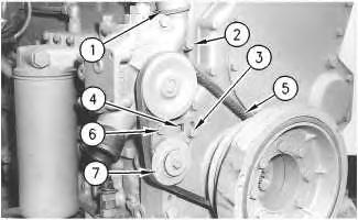
1. Drain the coolant from the cooling system into a suitable container for storage or for disposal.
2. Use hole (4) to remove tension from the V-belt.
Illustration 1
g01004978
3. Loosen bolts (3) and (6) on idler pulley assembly (7).
Note: For information on the reusability of idler pulley assembly (7), refer to Guideline For Reusable Parts And Salvage Operations, SEBF8046, "Cast Iron and Steel Pulleys".
4. Remove water pump V-belt (5).
5. Loosen hose clamps (1). Disconnect the hose assembly between the water pump and the water temperature regulator housing.
6. Remove bolts (2) that hold the water pump to the front of the engine. Carefully remove the water pump and two O-ring seals from the front of the engine.
Shutdown SIS
Previous Screen
Product: EXCAVATOR
Model: EL200B EXCAVATOR 7DF
Configuration: E200B, EL200B TRACK-TYPE EXCAVATORS 7DF00001-UP (MACHINE) POWERED BY 3116 ENGINE
Disassembly and Assembly
446 and 446B Backhoe Loaders, Lexion 450 Combine, 3114 and 3116 Engines, IT18F Integrated Toolcarrier, D6M Track-Type Tractor and 928F, 950F and 950G
Wheel Loaders
Water Pump - Disassemble
SMCS - 1361-015
Disassembly Procedure
Table 1
Required Tools Tool
Start By:
a. Remove the water pump. Refer to Disassembly and Assembly, "Water Pump - Remove".
NOTICE
Care must be taken to ensure that fluids are contained during performance of inspection, maintenance, testing, adjusting, and repair of the product. Be prepared to collect the fluid with suitable containers before opening any compartment or disassembling any component containing fluids.
Refer to Special Publication, NENG2500, "Dealer Service Tool Catalog" for tools and supplies suitable to collect and contain fluids on Cat products.
Dispose of all fluids according to local regulations and mandates.
g00614231
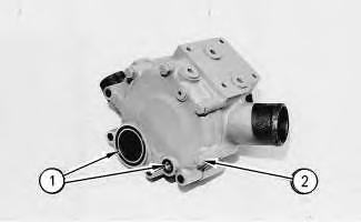
1. Remove O-ring seals (1) from the rear cover of the water pump. Remove bolts (2) and the washers. Remove the rear cover and the gasket.
g00614234
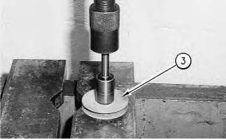
2. Position the water pump in a press. Use spacer plates to level the water pump.
3. Push the shaft and pulley (3) out of impeller (4) with a suitable drive plate from Tooling (A) and a press. Remove the impeller.
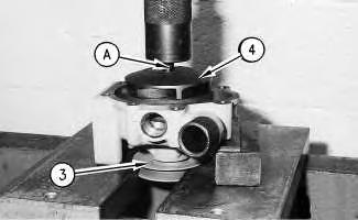
Note: For information on the reusability of pulley (3), refer to Guideline For Reusable Parts And Salvage Operations, SEBF8046, "Cast Iron and Steel Pulleys".
Note: The new 7E-0321 Pump Impeller, 153-9123 Impeller and a 109-5324 Impeller can be removed with a bolt. Insert a bolt 0.75 inch into the thread insert of the impeller. Turn the bolt inward toward the shaft. Twist and pull the impeller out of the pump.
Illustration 1 Illustration 2Note: Do not allow the shaft and the pulley to fall to the floor when the shaft and the pulley are removed.
4. Continue to push the shaft and pulley (3) out of seal (5) and the water pump housing.
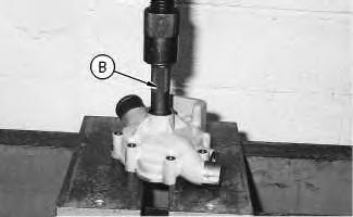 Illustration 3
g00614238
Illustration 4
g00614253
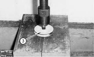
5. Remove seal (5) from the water pump housing with the handle from Tooling (B) and a press.
Illustration 5
g00614261
Illustration 3
g00614238
Illustration 4
g00614253
5. Remove seal (5) from the water pump housing with the handle from Tooling (B) and a press.
Illustration 5
g00614261
Shutdown SIS
Previous Screen
Product: EXCAVATOR
Model: EL200B EXCAVATOR 7DF
Configuration: E200B, EL200B TRACK-TYPE EXCAVATORS 7DF00001-UP (MACHINE) POWERED BY 3116 ENGINE
Disassembly and Assembly
446 and 446B Backhoe Loaders, Lexion 450 Combine, 3114 and 3116 Engines, IT18F Integrated Toolcarrier, D6M Track-Type Tractor and 928F, 950F and 950G
Wheel Loaders
Water Pump - Assemble
SMCS - 1361-016
Assembly Procedure
Table 1
Required Tools Tool
NOTICE
Keep all parts clean from contaminants.
Contaminants may cause rapid wear and shortened component life.
1. Install the shaft and the bearing into pulley (3) with a press. Install the shaft until the shaft is flush with the end of pulley (3).
2. Press the shaft, the bearing, and pulley (3) as a unit into the water pump housing. The distance between the front of pulley (3) and the machined surface of the water pump housing must be 103.8 ± 0.3 mm (4.09 ± 0.01 inch).
Note: For information on the reusability of pulley (3), refer to Guideline For Reusable Parts And Salvage Operations, SEBF8046, "Cast Iron and Steel Pulleys".
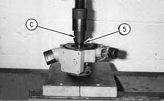
3. Install seal (5) in the water pump housing with Tooling (C).
Illustration 1 g00614283 Illustration 2 g01004707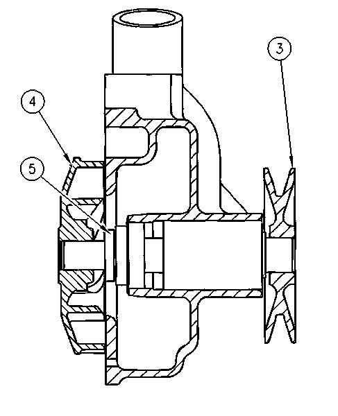
5. Install a new gasket between the rear cover of the water pump and the water pump housing. Position the gasket and the cover on the water pump housing. Install bolts (2) and the washers.
6. Install new O-ring seals (1) in the rear cover.
End By:
a. Install the water pump. Refer to Disassembly and Assembly, "Water Pump - Install".
Copyright 1993 - 2019 Caterpillar Inc. All Rights Reserved. Private Network For SIS Licensees.
Fri Sep 13 22:14:06 UTC+0800 2019
Shutdown SIS
Previous Screen
Product: EXCAVATOR
Model: EL200B EXCAVATOR 7DF
Configuration: E200B, EL200B TRACK-TYPE EXCAVATORS 7DF00001-UP (MACHINE) POWERED BY 3116 ENGINE
Disassembly and Assembly
446 and 446B Backhoe Loaders, Lexion 450 Combine, 3114 and 3116 Engines, IT18F Integrated Toolcarrier, D6M Track-Type Tractor and 928F, 950F and 950G
Wheel Loaders
Water Pump - Install
SMCS - 1361-012
Installation procedure
NOTICE
Keep all parts clean from contaminants.
Contaminants may cause rapid wear and shortened component life.
NOTICE
Care must be taken to ensure that fluids are contained during performance of inspection, maintenance, testing, adjusting, and repair of the product. Be prepared to collect the fluid with suitable containers before opening any compartment or disassembling any component containing fluids.
Refer to Special Publication, NENG2500, "Dealer Service Tool Catalog" for tools and supplies suitable to collect and contain fluids on Cat products.
Dispose of all fluids according to local regulations and mandates.
Suggest:
If the above button click is invalid.
Please download this document first, and then click the above link to download the complete manual.
Thank you so much for reading

Illustration 1
g01004978
1. Install new O-ring seals in the cover of the water pump. Position the water pump on the front of the engine. Install bolts (2).
2. Connect the hose assembly between the water pump and the water temperature regulator housing. Tighten hose clamps (1) that hold the hose in position.
3. Position V-belt (5) on the idler pulley assembly (7).
Note: For information on the reusability of idler pulley assembly (7), refer to Guideline For Reusable Parts And Salvage Operations, SEBF8046, "Cast Iron and Steel Pulleys".
4. Adjust the tension on the water pump V-belt (5).
5. Use hole (4) to apply tension to the V-belt. Refer to Specifications, "Belt Tensioner Chart" for the correct tension on the belt.
6. Fill the cooling system to the correct level. Refer to the Operation and Maintenance Manual, "Refill Capacities" topic for the correct fluid and the correct filling procedure.