Service
Shutdown SIS
Previous Screen
Product: EXCAVATOR
Model: E240C EXCAVATOR 2RL
Configuration: E240C, EL240C TRACK-TYPE EXCAVATORS 2RL00001-UP (MACHINE) POWERED BY 3116 ENGINE
Disassembly and Assembly
446 and 446B Backhoe Loaders, Lexion 450 Combine, 3114 and 3116 Engines, IT18F Integrated Toolcarrier, D6M Track-Type Tractor and 928F, 950F and 950G
Wheel Loaders
Flywheel Housing - Remove and Install
SMCS - 1157-010
Removal Procedure Table 1
Required Tools
Tool Part Number Part Description Qty
A 138-7573 Link Bracket 2
Start By:
a. Remove the flywheel. Refer to Disassembly and Assembly, "Flywheel - Remove".
NOTICE
Keep all parts clean from contaminants.
Contaminants may cause rapid wear and shortened component life.
NOTICE
Care must be taken to ensure that fluids are contained during performance of inspection, maintenance, testing, adjusting, and repair of the product. Be prepared to collect the fluid with suitable containers
before opening any compartment or disassembling any component containing fluids.
Refer to Special Publication, NENG2500, "Dealer Service Tool Catalog" for tools and supplies suitable to collect and contain fluids on Cat products.
Dispose of all fluids according to local regulations and mandates.
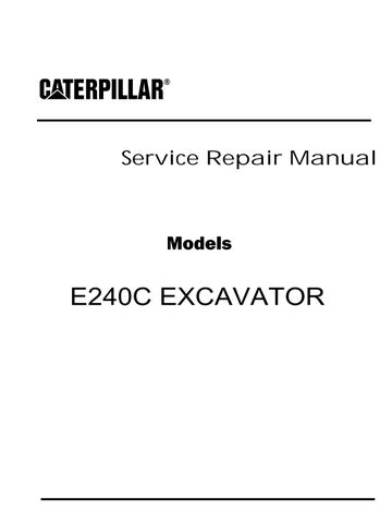
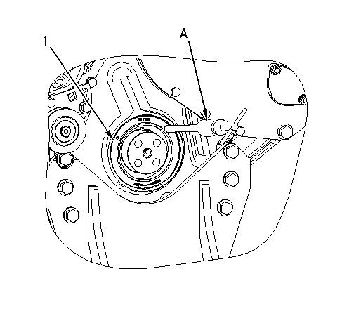
Illustration 1
g01027146
1. Fasten Tooling (A) and a suitable lifting device to flywheel housing (1).
2. Remove bolts (2) and bolt (3) that fastens the flywheel housing to the cylinder block.
3. Remove bolts (4). Remove flywheel housing (1). The weight of flywheel housing (1) is approximately 25 kg (55 lb).
Installation Procedure Table 2
Required Tools
A 138-7573 Link Bracket 2
B 1U-8846 Gasket Sealant 1
NOTICE
Keep all parts clean from contaminants.
Contaminants may cause rapid wear and shortened component life.
1. Apply Tooling (B) to the entire mounting face of the flywheel housing prior to installation.
Illustration 2 g01027146
2. Fasten Tooling (A) and a suitable lifting device to flywheel housing (1). The weight of flywheel housing (1) is approximately 25 kg (55 lb). Position flywheel housing (1) on the cylinder block. Install bolts (4).
3. Install bolts (2) and bolt (3).
End By:
Shutdown SIS
Previous Screen
Product: EXCAVATOR
Model: E240C EXCAVATOR 2RL
Configuration: E240C, EL240C TRACK-TYPE EXCAVATORS 2RL00001-UP (MACHINE) POWERED BY 3116 ENGINE
Disassembly and Assembly
446 and 446B Backhoe Loaders, Lexion 450 Combine, 3114 and 3116 Engines, IT18F Integrated Toolcarrier, D6M Track-Type Tractor and 928F, 950F and 950G
Wheel Loaders
Vibration Damper and Pulley - Remove and Install
SMCS - 1205-010
Removal Procedure
NOTICE
Keep all parts clean from contaminants.
Contaminants may cause rapid wear and shortened component life.
NOTICE
Care must be taken to ensure that fluids are contained during performance of inspection, maintenance, testing, adjusting, and repair of the product. Be prepared to collect the fluid with suitable containers before opening any compartment or disassembling any component containing fluids.
Refer to Special Publication, NENG2500, "Dealer Service Tool Catalog" for tools and supplies suitable to collect and contain fluids on Cat products.
Dispose of all fluids according to local regulations and mandates.
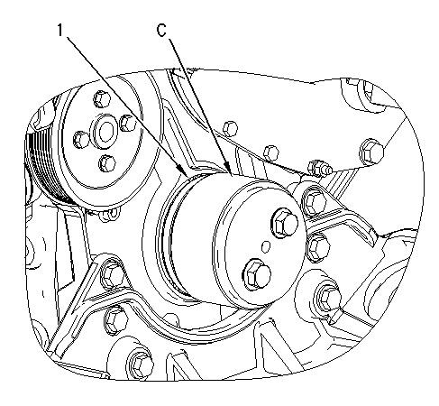
1. Remove bolts (2), crankshaft vibration damper (3), and spacers from the crankshaft pulley.
Note: For information on the reusability of the vibration damper on 3114 and 3116 engines, refer to Guideline For Reusable Parts And Salvage Operations, SEBF8220, "Specifications for Damper Inspection 3114 and 3116 Engines".
2. Loosen the tension on water pump drive belt (1). Remove the belt from the crankshaft pulley.
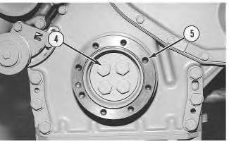
3. Remove bolts (4) and the washers.
4. Remove crankshaft pulley (5).
Note: For information on the reusability of the crankshaft pulley, refer to Guideline For Reusable Parts And Salvage Operations, SEBF8046, "Cast Iron and Steel Pulleys".
Installation Procedure
Keep all parts clean from contaminants.
Illustration 1 g00691836 Illustration 2 g00691831Contaminants may cause rapid wear and shortened component life.
1. Position crankshaft pulley (5) on the crankshaft. Install bolts (4) and tighten the bolts to a torque of 160 ± 30 N·m (118 ± 22 lb ft).
Note: For information on the reusability of the crankshaft pulley, refer to Guideline For Reusable Parts And Salvage Operations, SEBF8046, "Cast Iron and Steel Pulleys".
2. Install water pump drive belt (1).
Note: Check the alignment marks on the rubber vibration dampers for proper alignment. The rubber vibration damper should be replaced if the rubber vibration damper is out of alignment. Refer to Specifications, "Vibration Damper".
3. Install spacers and crankshaft vibration damper (3). Tighten bolts (2) to a torque of 55 ± 10 N·m (40 ± 7 lb ft).
Note: For information on the reusability of the vibration damper on 3114 and 3116 engines, refer to Guideline For Reusable Parts And Salvage Operations, SEBF8220, "Specifications for Damper Inspection 3114 and 3116 Engines".
Illustration 3
g00691831
Illustration 4
g00691836
4. Adjust the tension of water pump drive belt (1). Refer to the Specifications Module, "Belt Tension Chart". Also, refer to the Operation and Maintenance Manual, "Belt - Inspect". Copyright 1993 - 2019 Caterpillar Inc.
Shutdown SIS
Previous Screen
Product: EXCAVATOR
Model: E240C EXCAVATOR 2RL
Configuration: E240C, EL240C TRACK-TYPE EXCAVATORS 2RL00001-UP (MACHINE) POWERED BY 3116 ENGINE
Disassembly and Assembly
446 and 446B Backhoe Loaders, Lexion 450 Combine, 3114 and 3116 Engines, IT18F Integrated Toolcarrier, D6M Track-Type Tractor and 928F, 950F and 950G
Wheel Loaders
Crankshaft Front Seal - Remove
SMCS - 1160-011
Removal Procedure
Table 1
Required Tools
Tool Part Number Part Description Qty
A 1U-7600 Slide Hammer Puller 1
B 1U-8145 Drill Bit 1
Start By:
a. Remove the vibration damper and the pulley. Refer to Disassembly and Assembly, "Vibration Damper and Pulley - Remove and Install".
NOTICE
Keep all parts clean from contaminants.
Contaminants may cause rapid wear and shortened component life.
1. Use Tooling (B) and carefully drill three evenly spaced holes in crankshaft front seal (1).
2. Alternate between the drilled holes and use Tooling (A) to remove crankshaft front seal (1).
Shutdown SIS
Previous Screen
Product: EXCAVATOR
Model: E240C EXCAVATOR 2RL
Configuration: E240C, EL240C TRACK-TYPE EXCAVATORS 2RL00001-UP (MACHINE) POWERED BY 3116 ENGINE
Disassembly and Assembly
446 and 446B Backhoe Loaders, Lexion 450 Combine, 3114 and 3116 Engines, IT18F Integrated Toolcarrier, D6M Track-Type Tractor and 928F, 950F and 950G
Wheel Loaders
Crankshaft Front Seal - Install
SMCS - 1160-012
Installation Procedure Table 1
Required Tools
Tool Part Number Part Description Qty
C 1U-7430 Front Seal Installer 1
NOTICE
Keep all parts clean from contaminants.
Contaminants may cause rapid wear and shortened component life.
1. Use Tooling (C) to install crankshaft front seal (1).
Note: The crankshaft seal is designed to be installed dry.
End By:
a. Install the vibration damper and the pulley. Refer to Disassembly and Assembly, "Vibration Damper and Pulley - Remove and Install".
Shutdown SIS
Previous Screen
Product: EXCAVATOR
Model: E240C EXCAVATOR 2RL
Configuration: E240C, EL240C TRACK-TYPE EXCAVATORS 2RL00001-UP (MACHINE) POWERED BY 3116 ENGINE
Disassembly and Assembly
446 and 446B Backhoe Loaders, Lexion 450 Combine, 3114 and 3116 Engines, IT18F Integrated Toolcarrier, D6M Track-Type Tractor and 928F, 950F and 950G
Wheel Loaders
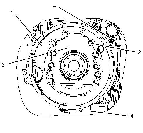
Front Cover - Remove
SMCS - 1166-011
Removal Procedure
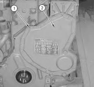
Illustration 1
Note: It is not necessary to remove the vibration damper and the crankshaft pulley in order to remove the front cover.
1. Remove bolts (1) from front cover (2).
2. Remove front cover (2) and the gasket from the front of the engine.
Shutdown SIS
Previous Screen
Product: EXCAVATOR
Model: E240C EXCAVATOR 2RL
Configuration: E240C, EL240C TRACK-TYPE EXCAVATORS 2RL00001-UP (MACHINE) POWERED BY 3116 ENGINE
Disassembly and Assembly
446 and 446B Backhoe Loaders, Lexion 450 Combine, 3114 and 3116 Engines, IT18F Integrated Toolcarrier, D6M Track-Type Tractor and 928F, 950F and 950G
Wheel Loaders
Front Cover - Install
SMCS - 1166-012
Installation Procedure
NOTICE
Keep all parts clean from contaminants.
Contaminants may cause rapid wear and shortened component life.
Illustration 1
1. Install a new gasket (3) on the front cover (2) .
g00752906
Illustration 2
g00629709
2. Install the gasket and front cover (2) on the front of the engine.
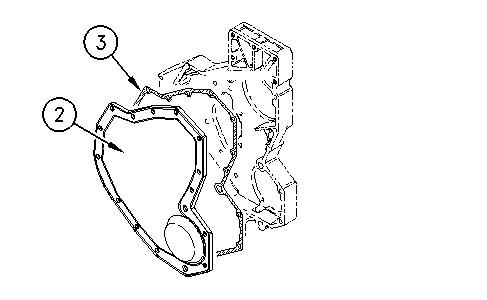
3. Install bolts (1) in front cover (2) .
Copyright 1993 - 2019 Caterpillar Inc. All Rights Reserved. Private Network For SIS Licensees.
Shutdown SIS
Previous Screen
Product: EXCAVATOR
Model: E240C EXCAVATOR 2RL
Configuration: E240C, EL240C TRACK-TYPE EXCAVATORS 2RL00001-UP (MACHINE) POWERED BY 3116 ENGINE
Disassembly and Assembly
446 and 446B Backhoe Loaders, Lexion 450 Combine, 3114 and 3116 Engines, IT18F Integrated Toolcarrier, D6M Track-Type Tractor and 928F, 950F and 950G
Wheel Loaders
Gear Group (Front) - Remove
SMCS - 1206-011
Removal Procedure Table 1
Required Tools
Tool Part Number Part Description Qty
A 1P-0520 Driver Gp 1
Start By:
a. Remove the crankshaft vibration damper. Refer to Disassembly and Assembly, "Vibration Damper and Pulley - Remove and Install".
b. Remove the crankshaft front seal. Refer to Disassembly and Assembly, "Crankshaft Front Seal - Remove".
c. Remove the camshaft. Refer to Disassembly and Assembly, "Camshaft - Remove".
d. Remove the front housing. Refer to Disassembly and Assembly, "Housing (Front)Remove".
Note: For information on reusability of the camshaft idler gear, refer to Guideline For Reusable Parts And Salvage Operations, SEBF8045, "Timing Gears for All Engines".
1. Place the engine at the Top Center position. The timing marks should be in line with the crankshaft gear.
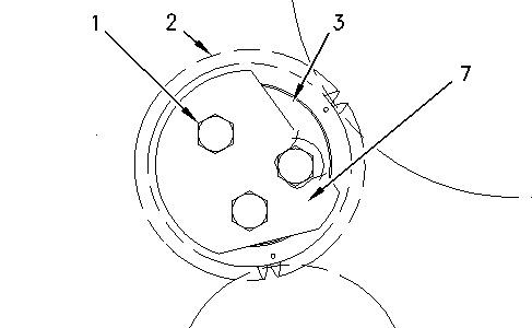
Illustration 1
g01005265
2. Identify the type of idler gear on the engine. Remove bolts (1) that hold the idler gear to the block. Remove plate (7).
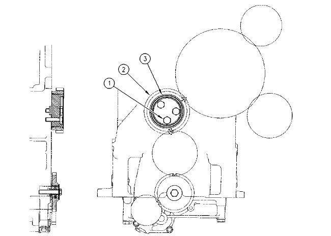
Illustration 2
g00677884
3. Identify the location of timing marks (4) and (5) on the camshaft idler gear. Identify the location of timing mark (6) on the crankshaft drive gear.

4. Remove idler shaft (3) and camshaft idler gear (2). Separate idler gear (2) from idler shaft (3) and remove the sleeve bearing from the camshaft idler gear.
5. Use Tooling (A) and a press to remove the bearing.
Copyright 1993 - 2019 Caterpillar Inc.
Shutdown SIS
Previous Screen
Product: EXCAVATOR
Model: E240C EXCAVATOR 2RL
Configuration: E240C, EL240C TRACK-TYPE EXCAVATORS 2RL00001-UP (MACHINE) POWERED BY 3116 ENGINE
Disassembly and Assembly
446 and 446B Backhoe Loaders, Lexion 450 Combine, 3114 and 3116 Engines, IT18F
Integrated Toolcarrier, D6M Track-Type Tractor and 928F, 950F and 950G Wheel Loaders
Gear Group (Front) - Install
SMCS - 1206-012
Installation Procedure
Table 1
Required Tools
Tool Part Number Part Description Qty
A 1P-0520 Driver Gp 1
Note: For information on reusability of the camshaft idler gear, refer to Guideline For Reusable Parts And Salvage Operations, SEBF8045, "Timing Gears for All Engines".
1. Use Tooling (A) and a suitable press to install the sleeve bearing in the camshaft idler gear.
2. Install the bearing sleeve to a depth of 0.40 ± 0.25 mm (0.016 ± 0.010 inch) below the front face of the gear.
3. Place the idler shaft (3) on the cylinder block. Install bolts (1) that hold the idler shaft to the cylinder block. Tighten the bolts to a torque of 70 ± 15 N·m (51 ± 11 lb ft).
4. Install camshaft idler gear (2) on idler shaft (3). The timing marks should face outward.
5. Align the timing marks on camshaft idler gear (2) with the timing marks on the crankshaft drive gear.
1. Use Tooling (A) and a suitable press and install the sleeve bearing in the camshaft idler gear.
2. Install plate (4) on the back of idler shaft (3). Position idler gear assembly on the cylinder block. Install bolts that hold the idler gear to the engine block. Tighten the bolts to a torque of 70 ± 15 N·m (51 ± 11 lb ft).
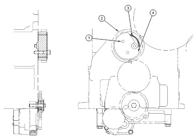
3. Install camshaft idler gear (2) on idler shaft (3). The timing marks should face outward.
4. Align the timing marks on camshaft idler gear (2) with the timing marks on the crankshaft drive gear.
Illustration 2 g00644057 Type 2Type 3
1. Position idler shaft (3) on the cylinder block. Install the shortest bolt in the recessed hole in idler shaft (3). This bolt will hold the shaft in position on the cylinder block.
2. Install camshaft idler gear (2) on idler shaft (3). The timing marks should face outward.
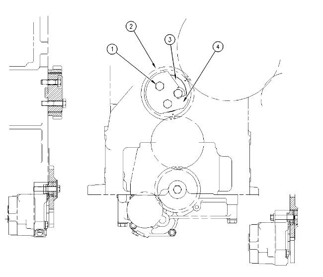
3. Align the timing marks on idler gear (2) with the timing marks on the camshaft drive gear.
4. Position plate (4) over the gear and install the remaining bolts (1). Tighten bolts (1) to a torque of 70 ± 15 N·m (51 ± 11 lb ft).
End By:
a. Install the front housing. Refer to Disassembly and Assembly, "Housing (Front) - Install".
b. Install the camshaft. Refer to Disassembly and Assembly, "Camshaft - Install".
c. Install the crankshaft front seal. Refer to Disassembly and Assembly, "Crankshaft Front SealInstall".
d. Install the crankshaft vibration damper and pulley. Refer to Disassembly and Assembly, "Vibration Damper and Pulley -Remove and Install".
Shutdown SIS
Previous Screen
Product: EXCAVATOR
Model: E240C EXCAVATOR 2RL
Configuration: E240C, EL240C TRACK-TYPE EXCAVATORS 2RL00001-UP (MACHINE) POWERED BY 3116 ENGINE
Disassembly and Assembly
446 and 446B Backhoe Loaders, Lexion 450 Combine, 3114 and 3116 Engines, IT18F Integrated Toolcarrier, D6M Track-Type Tractor and 928F, 950F and 950G
Wheel Loaders
Housing (Front) - Remove
SMCS - 1151-011
Removal Procedure
Start By:
a. Remove the crankshaft vibration damper. Refer to Disassembly and Assembly, "Vibration Damper and Pulley - Remove and Install".
b. Remove the crankshaft front seal. Refer to Disassembly and Assembly, "Crankshaft Front Seal - Remove".
c. Remove the camshaft. Refer to Disassembly and Assembly, "Camshaft - Remove".
NOTICE
Care must be taken to ensure that fluids are contained during performance of inspection, maintenance, testing, adjusting, and repair of the product. Be prepared to collect the fluid with suitable containers before opening any compartment or disassembling any component containing fluids.
Refer to Special Publication, NENG2500, "Dealer Service Tool Catalog" for tools and supplies suitable to collect and contain fluids on Cat products.
Dispose of all fluids according to local regulations and mandates.
1. Remove any external components, if equipped.
Suggest:
If the above button click is invalid.
Please download this document first, and then click the above link to download the complete manual.
Thank you so much for reading

2. Support the front of the engine.

3. Remove bolts (2) and remove front engine support.
4. Remove bolts (1) and belt tightener (3).
5. Remove bolts (5) that fasten front housing (4) to the cylinder block and to the engine oil pan. Remove front housing (4). Clean the sealant from front housing (4) and the cylinder block.
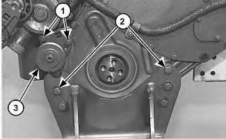 Illustration 1 g01011903
Illustration 2 g01011906
Illustration 1 g01011903
Illustration 2 g01011906