Service
Repair Manual Models
D5C III TRACK-TYPE
TRACTOR Dozer
Shutdown SIS
Previous Screen
Product: TRACK-TYPE TRACTOR
Model: D5C III TRACK-TYPE TRACTOR 9DL
Disassembly and Assembly
3046 Engine For Caterpillar Built Machines
Vibration Damper and Pulley - Remove and Install
SMCS - 1205-010
Removal Procedure Table 1
Required Tools
Start By:
A. Remove the V-belts. Refer to Disassembly and Assembly, "V-Belts - Remove and Install".
NOTICE
Keep all parts clean from contaminants.
Contaminants may cause rapid wear and shortened component life.
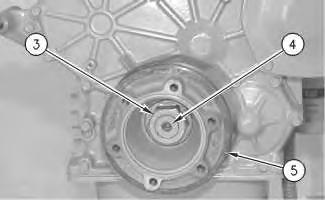
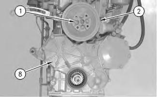
1. Remove six bolts (1) and the washers from vibration damper (2). Remove vibration damper (2) from crankshaft pulley (5) .
Note: Inspect the vibration damper for leaks and dents. If either condition exists, replace the vibration damper with a new part.
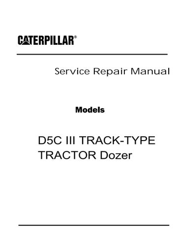
3. Use Tool (A) and remove nut (3) and the washer from the crankshaft.
Illustration 1 g00528749 2. Illustration 2 g00559259Illustration 3
g00559308
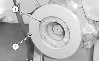
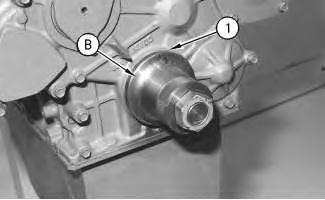
4. If necessary, use Tool (B) and remove crankshaft pulley (5) .
Installation Procedure
NOTICE
Keep all parts clean from contaminants. Contaminants may cause rapid wear and shortened component life.
Illustration 4
g00559259
1. Install crankshaft pulley (5) with the washer and nut (3) onto crankshaft (4) .
2. Use Tool (A) to tighten nut (3) to a torque of 490 ± 10 N·m (360 ± 7 lb ft). Hit nut (3) with a hammer and torque the bolt again to 490 ± 10 N·m (360 ± 7 lb ft).
3. Use six bolts (1) and the washers in order to install vibration damper (2) on the crankshaft pulley.
End By: Install the V-belts. Refer to Disassembly and Assembly, "V-Belts - Install".
Copyright 1993 - 2019 Caterpillar Inc. All Rights Reserved.
Illustration 5 g00528749Shutdown SIS
Previous Screen
Product: TRACK-TYPE TRACTOR
Model: D5C III TRACK-TYPE TRACTOR 9DL
Configuration: D5C D5C LGP XL Series III Tractors
Disassembly and Assembly
3046 Engine For Caterpillar Built Machines
Crankshaft Front Seal - Remove
SMCS - 1160-011
Removal Procedure Table 1
Required Tools Tool
A 1U-7600 Slide Hammer Puller 1
Start By:
A. Remove the vibration damper and the crankshaft pulley. Refer to Disassembly and Assembly, "Vibration Damper and Pulley - Remove and Install".
NOTICE
Keep all parts clean from contaminants.
Contaminants may cause rapid wear and shortened component life.
NOTICE
Care must be taken to ensure that fluids are contained during performance of inspection, maintenance, testing, adjusting and repair of the machine. Be prepared to collect the fluid with suitable containers before opening any compartment or disassembling any component containing fluids.
Refer to Special Publication, NENG2500, "Caterpillar Tools and Shop Products Guide", for tools and supplies suitable to collect and contain fluids in Caterpillar machines.
Dispose of all fluids according to local regulations and mandates.
g00529162
1. Drill three evenly spaced 3 mm (.12 inch) holes in crankshaft front seal (1) .
2. Use Tool (A) and remove crankshaft front seal (1) .
Copyright 1993 - 2019 Caterpillar Inc. All Rights Reserved. Private Network For SIS Licensees.
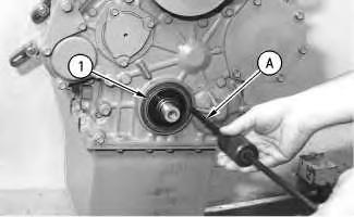 Illustration 1
Previous Screen
Product: TRACK-TYPE TRACTOR
Model: D5C III TRACK-TYPE TRACTOR 9DL Configuration: D5C D5C LGP XL Series III Tractors
Disassembly and Assembly
3046 Engine For Caterpillar Built Machines
Crankshaft Front Seal - Install
SMCS - 1160-012
Installation Procedure Table 1
Required Tools
NOTICE
Keep all parts clean from contaminants.
Contaminants may cause rapid wear and shortened component life.
Shutdown SIS
Illustration 1
g00529163
1. Clean the faces of all the mating parts. Apply a thin coat of clean engine oil to a new crankshaft front seal.
2. Install new crankshaft front seal (1) with Tool (A) .
3. Remove Tool (A) and check crankshaft front seal (1) for correct installation.
4. Apply clean engine oil to the face of the crankshaft pulley that will be in contact with the new crankshaft front seal.
End By: Install the vibration damper and the pulley. Refer to Disassembly and Assembly, "Vibration Damper and Pulley - Remove and Install".
- 2019
Shutdown SIS
Previous Screen
Product: TRACK-TYPE TRACTOR
Model: D5C III TRACK-TYPE TRACTOR 9DL
Configuration: D5C D5C LGP XL Series III Tractors Power Shift
Disassembly and Assembly
3046 Engine For Caterpillar Built Machines
Gear Group (Front) - Remove - Idler Gear Only
SMCS - 1206-011
Removal Procedure Table 1
Required Tools
Tool Part Number Part Description Qty
A 9U-6148 Idler Shaft Puller 1
Start By:
A. Remove the front housing. Refer to Disassembly and Assembly, "Housing (Front)Remove".
NOTICE
Keep all parts clean from contaminants.
Contaminants may cause rapid wear and shortened component life.
NOTICE
Care must be taken to ensure that fluids are contained during performance of inspection, maintenance, testing, adjusting and repair of the product. Be prepared to collect the fluid with suitable containers before opening any compartment or disassembling any component containing fluids.
Refer to Special Publication, NENG2500, "Caterpillar Tools and Shop Products Guide" for tools and supplies suitable to collect and contain fluids on Caterpillar products.
Dispose of all fluids according to local regulations and mandates.
Note: Before removal, ensure that the marks on the timing gears are in alignment. Align the fuel injection drive gear with the "33" mark with the "3" mark on the idler gear. Make an alignment of the "2" mark on the camshaft gear with the "22" mark on the idler gear. Align the "1" mark on the crankshaft gear with the "11" mark on the idler gear. The No. 1 cylinder is at the top center position when these marks are in alignment.
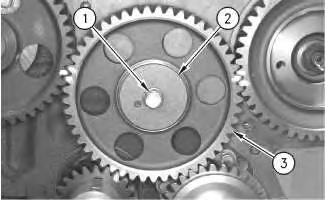
1. Remove idler gear bolt (1) and the washer from the idler gear shaft .
2. Remove thrust plate (2) .
3. Remove idler gear (3) .
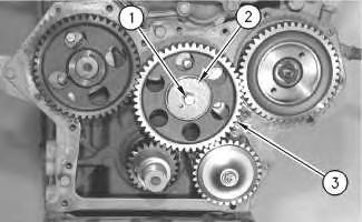
Illustration 1 g00559575 Illustration 2 g005595364. Use Tool (A) and remove idler shaft (4) from the cylinder block.
5. If necessary, remove five bolts (5) that hold front plate (6) to the cylinder block.
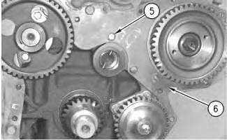
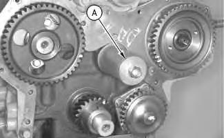
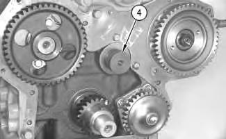 Illustration 3 g00559567
Illustration 4 g00559569
Illustration 5 g00559572
Illustration 3 g00559567
Illustration 4 g00559569
Illustration 5 g00559572
6. Remove front plate (6) and the gasket.
Note: See the following list for the removal of the other gears in the front gear group.
• In order to remove the camshaft gear, refer to Disassembly and Assembly, "CamshaftRemove and Install".
• In order to remove the fuel injection pump gear, refer to Disassembly and Assembly, "Fuel Injection Pump Housing and Governor - Remove".
• In order to remove the gear to the engine oil pump, refer to Disassembly and Assembly, "Engine Oil Pump - Remove".
• In order to remove the crankshaft front gear, refer to Disassembly and Assembly, "Crankshaft Gear - Remove and Install".
Copyright 1993 - 2019 Caterpillar Inc.
All Rights Reserved.
Private Network For SIS Licensees.
Thu Dec 26 11:00:45 UTC+0800 2019
Previous Screen
Product: TRACK-TYPE TRACTOR
Model: D5C III TRACK-TYPE TRACTOR 9DL
Configuration: D5C D5C LGP XL Series III Tractors Power Shift
Disassembly and Assembly
3046 Engine For Caterpillar Built Machines
Gear Group (Front) - Install - Idler Gear Only
SMCS - 1206-012
Installation Procedure
NOTICE
Keep all parts clean from contaminants.
Contaminants may cause rapid wear and shortened component life.
Shutdown SIS
Illustration 1
1. Install a new gasket and front plate (6) .
g00559572
Note: Ensure that all mating surfaces are clean and free of old gasket material.
2. Install five bolts (5) that hold front plate (6) to the cylinder block. Tighten these bolts to a torque of 10 to 13 N·m (7 to 10 lb ft).
Illustration 2 g00559567
3. Install idler shaft (4) onto the cylinder block.
Note: If necessary, cool the idler shaft to 0 °C (32 °F) before installation.
Illustration 3
g00559536
Note: Ensure that the marks on the timing gears are in alignment. Align the fuel injection drive gear with the "33" mark with the "3" mark on the idler gear. Make an alignment of the "2" mark on the camshaft gear with the "22" mark on the idler gear. Align the "1" mark on the crankshaft gear with the "11" mark on the idler gear. The No. 1 cylinder is at the top center position when these marks are in alignment.
4. Install idler gear (3) .
5. Install thrust plate (2) .
6. Install the washer and idler gear bolt (1) onto thrust plate (2). Tighten idler gear bolt (1) to a torque of 34 ± 5 N·m (25 ± 4 lb ft).
Note: For more information, refer to the Specifications Module, "Gear Group (Front)".
Note: See the following list for the installation of the other gears in the front gear group.
• In order to install the camshaft gear, refer to Disassembly and Assembly, "CamshaftRemove and Install".
• In order to install the fuel injection pump gear, refer to Disassembly and Assembly, "Fuel Injection Pump Housing and Governor - Install".
• In order to install the gear from the engine oil pump, refer to Disassembly and Assembly, "Engine Oil Pump - Install".
• In order to install the crankshaft front gear, refer to Disassembly and Assembly, "Crankshaft Front Gear - Remove and Install".
End By: Install the front housing. Refer to Disassembly and Assembly, "Housing (Front)Install".
Copyright 1993 - 2019 Caterpillar Inc. All Rights Reserved. Private Network For SIS Licensees.
Thu Dec 26 11:01:44 UTC+0800 2019
Shutdown SIS
Previous Screen
Product: TRACK-TYPE TRACTOR
Model: D5C III TRACK-TYPE TRACTOR 9DL
Configuration: D5C D5C LGP XL Series III Tractors Power Shift
Disassembly and Assembly
3046 Engine For Caterpillar Built Machines
Housing (Front) - Remove
SMCS - 1162-011
Removal Procedure
Start By:
A. Remove the alternator. Refer to Disassembly and Assembly, "Alternator - Remove and Install".
B. Remove the vibration damper and the pulley. Refer to Disassembly and Assembly, "Vibration Damper and Pulley - Remove and Install".
NOTICE
Keep all parts clean from contaminants.
Contaminants may cause rapid wear and shortened component life.
NOTICE
Care must be taken to ensure that fluids are contained during performance of inspection, maintenance, testing, adjusting and repair of the product. Be prepared to collect the fluid with suitable containers before opening any compartment or disassembling any component containing fluids.
Refer to Special Publication, NENG2500, "Caterpillar Tools and Shop Products Guide" for tools and supplies suitable to collect and contain fluids on Caterpillar products.
Dispose of all fluids according to local regulations and mandates.
Illustration 1 g00560210
1. Remove four bolts (1) and the washers from fan pulley (2) .
2. Remove fan pulley (2) .
Illustration 2 g00529390
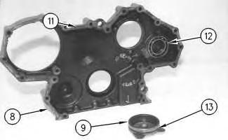
3. If equipped, remove bolts (3) and the washers from front housing (8) .
4. Remove five bolts (4) and the washers from cover (5) for the fuel injection pump gear.
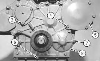
5. Remove cover (5) for the engine oil pump.
6. Remove six bolts (6) and the washers that secure the engine oil pan to the front housing.
7. Remove bolts (7) that secure front housing (8) to the cylinder block.
8. Remove front housing (8) .
g00529391
9. If equipped, remove cover (9) for the camshaft gear.
10. Check the condition of crankshaft front seal (10). If the crankshaft front seal is worn or damaged, use a new part for replacement. Refer to Disassembly and Assembly, "Crankshaft Front Seal - Remove" for removal of the crankshaft front seal .
g00529392
11. Remove bearing (12), if equipped. If the bearing is worn or damaged, use a new part for replacement.
12. Clean old gasket material (11) from the contact surface of front housing (8) and the timing gear plate.
Copyright 1993 - 2019 Caterpillar Inc. All Rights Reserved. Private Network For SIS Licensees.
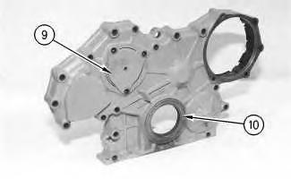 Illustration 3
Illustration 4
Illustration 3
Illustration 4
Shutdown SIS
Previous Screen
Product: TRACK-TYPE TRACTOR
Model: D5C III TRACK-TYPE TRACTOR 9DL
Configuration: D5C D5C LGP XL Series III Tractors Power Shift
Disassembly and Assembly
3046 Engine For Caterpillar Built Machines
Housing (Front) - Install
SMCS - 1162-012
Installation Procedure
NOTICE
Keep all parts clean from contaminants.
(MACHINE) POWERED BY 3046 Engine
Contaminants may cause rapid wear and shortened component life.
Note: Check the condition of the gaskets and the O-ring seals. If the gaskets or the O-ring seals are damaged or worn, use new parts for replacement.
g00529392
1. Clean old gasket material (11) from the contact surface of front housing (8) and the timing gear plate. Install a new gasket.
2. Install bearing (12), if equipped. If the bearing is worn or damaged, use a new part for replacement.
3. Install O-ring seal (13) onto cover (9), if equipped.
4. Install a new crankshaft front seal (10), if the crankshaft front seal was removed. Refer to Disassembly and Assembly, "Crankshaft Front Seal - Install".
5. If equipped, install camshaft gear cover (9) onto front housing (8) .
6. Install front housing (8) .
7. Install bolts (7) in order to fasten front housing (8) onto the cylinder block.
8. Install the washers and six bolts (6) in order to secure front housing (8) onto engine oil pan.
9. Install cover (5) for fuel injection pump gear.
Illustration 2 g00529391 Illustration 3 g00529390Suggest:
If the above button click is invalid.
Please download this document first, and then click the above link to download the complete manual.
Thank you so much for reading

10. Install the washers and five bolts (4) in order to secure cover (5) for fuel injection pump gear onto front housing (8) .
11. If equipped, install the washers and bolts (3) in order to secure camshaft gear cover (9) onto front housing (8) .
12. Install fan pulley (2) .
13. Install the washers and four bolts (1) in order to secure fan pulley (2) onto the water pump.
End By:
a. Install the vibration damper and the pulley. Refer to Disassembly and Assembly, "Vibration Damper and Pulley - Remove and Install".
b. Install the alternator. Refer to Disassembly and Assembly, "Alternator - Remove and Install".
Copyright 1993 - 2019 Caterpillar Inc.
All Rights Reserved.
Private Network For SIS Licensees.
Illustration 4 g00560210