Service Repair Manual Models D25D, D30D, D350D ARTICULATED TRUCK
Shutdown SIS
Previous Screen
Product: ARTICULATED TRUCK
Model: D350D ARTICULATED TRUCK 9RF
Configuration: D25D, D30D, D350D ARTICULATED TRUCK 9RF00001-UP (MACHINE) POWERED BY 3306 ENGINE
Disassembly and Assembly
D25D,D30D AND D350D ARTICULATED DUMP TRUCKS VEHICLE SYSTEMS

Steering Control Valve
SMCS - 4307-010; 4307-015; 4307-016
Remove & Install Steering Control Valve
NOTE: If necessary, drain the oil at least halfway down the hydraulic tank.
NOTE: Put identification on all lines, hoses and tubes for installation purposes.
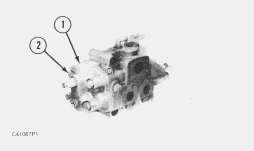
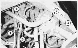
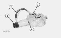
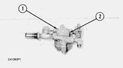
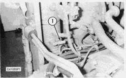
1. Remove lines (1) from the hoist control valve.
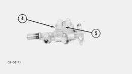
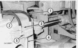
2. Remove bolts and flanges (2). Remove lines (4), (5) and (6) from the steering control valve.
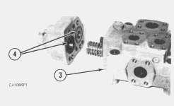
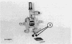
3. Remove mounting bolts (3) and then remove steering control valve (7). Weight of the steering control valve is 23 Kg (50 lb.).
NOTE: The following steps are for the installation of the steering control valve.
4. Put steering control valve (7) in position and install the bolts (3) that hold it.
5. Install lines (4), (5) and (6) on the steering control valve. Install bolts and flanges (2).
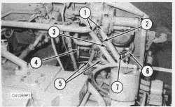
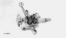
6. Install lines (1) on the hoist control valve.
7. Fill the hydraulic tank to the correct level. See the Maintenance Guide.
Media Number -SENR8210-01 Publication Date -01/03/2005 Date Updated -05/12/2017
SENR82100004
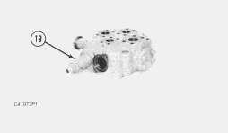
Disassemble Steering Control Valve
Start By: remove steering control valve
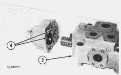
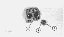
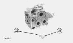
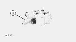
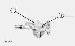
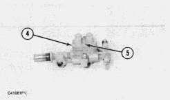
1. Remove bolts (2) and body (1).
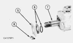
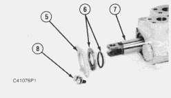
2. Remove and inspect seals (4) from the valve body (3).
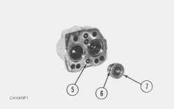
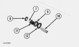
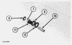
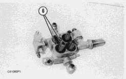
3. Remove seat (7). Remove and inspect seal (6).
4. Remove and inspect small O-ring seals (5) from the body (3).
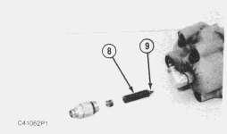
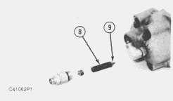
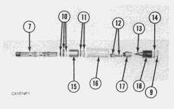
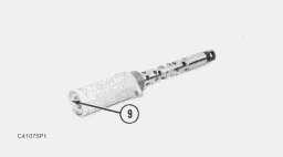
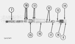
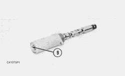
5. Remove plug, shims, spring (8) and valve (9) from the body (3).
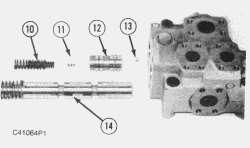
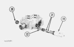
6. Remove directional valve spool assembly (14) from the valve body.
7. Remove springs (10) from the valve body.
8. Remove valve spool (12) from the valve body.
9. Remove shims (11) from the valve spool.
10. Remove seat (13) from the valve housing.
NOTICE
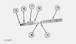
Bolt (15) holds spring (17) under compression.
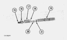
11. Remove bolt (15), spring retainer (16), spring (17), spacer (18), retainer (20) and shims (21) from valve spool (19).
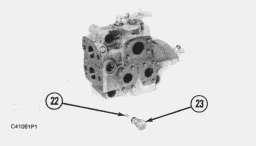
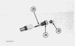
12. Remove plug (23), seat and ball (22) from the valve body. Remove and inspect the O-ring seals on the plug and seat.
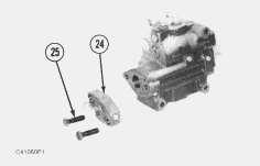
13. Remove bolts (25) and valve body flange (24) from the valve body.
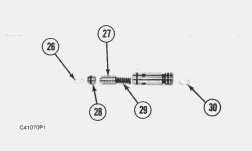
14. Remove plug (27), spring (28) and ball (26) from the valve body.
Assemble Steering Control Valve
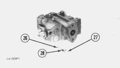
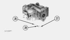
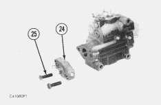
1. Install ball (26), spring (28) and plug (27) in the valve body.
2. Install valve body flange (24) and bolts (25) in the valve body.
NOTE: Inspect and replace all O-ring seals if necessary.
5. Install seat (13) in the valve housing.
6. Install shims (11) in the valve spool.
7. Install valve spool (12) in the valve body.
8. Install springs (10) in the valve body.
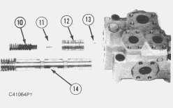
9. Install directional valve spool assembly (14) from the valve body.
10.
3. Install ball (22), seat and plug (23) in the valve body.
4. Install shims (21), retainer (20), spacer (18), spring (17), spring retainer (16) and bolt (15).
Install valve (9) spring (8), shims and plug in the body (3).
11.
12.
End By:
 Install small O-ring seals (5) in the body (3).
Install seal (6) on seat (7). Install seat (7) in the body.
13. Install seals (4) on valve body (3).
14. Install body (1) and bolts (2).
Install small O-ring seals (5) in the body (3).
Install seal (6) on seat (7). Install seat (7) in the body.
13. Install seals (4) on valve body (3).
14. Install body (1) and bolts (2).
Copyright
-
Caterpillar Inc. All Rights Reserved. Private Network For SIS Licensees. Thu Feb 13 07:27:47 UTC+0800 2020
a. install steering control valve
1993
2020
Shutdown SIS
Previous Screen
Product: ARTICULATED TRUCK
Model: D350D ARTICULATED TRUCK 9RF
Configuration: D25D, D30D, D350D ARTICULATED TRUCK 9RF00001-UP (MACHINE) POWERED BY 3306 ENGINE
Disassembly and Assembly
D25D,D30D AND D350D ARTICULATED DUMP TRUCKS VEHICLE SYSTEMS
Hoist Control Valve
SMCS - 5136-010; 5136-015; 5136-016
Remove & Install Hoist Control Valve
NOTE: Put identification on all lines, hoses and tubes for installation purposes.
1. Remove lines (1) and (4) from the hoist control valve.
2. Disconnect hydraulic lines (5) from the hoist control valve.
3. Remove control valve mounting bolts (2) to remove hoist control valve (3). Weight of the valve is 23 Kg (51 lb.).
NOTE: The following steps are for the installation of the hoist control valve.
4. Put hoist control valve (3) in position and install mounting bolts (2).
5. Connect hydraulic lines (5) to the hoist control valve.
6. Install lines (1) and (4) to the hoist control valve.
Disassemble Hoist Control Valve
Start By:
Media Number -SENR8210-01 Publication Date -01/03/2005 Date Updated -05/12/2017
SENR82100005
a. remove hoist control valve
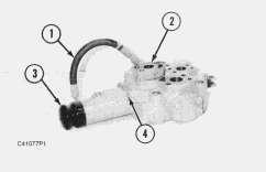
1. Disconnect line (1) from the relief valve.
2. Remove flange (2).
3. Remove boot (3) from cover.
4. Remove bolts (4) from cover.
5. Turn the control valve body around and remove two bolts (8).
6. Remove seal retainer (5). Remove seals (6) from the valve housing.
7. Pull main control spool assembly (7) from the valve housing.
8. Remove retainer ring (9) from the cover plate.
9. Remove cover plate (14), spring and spring retainers (18), poppet (13), detent cap (17), spring check valve (12), cover (16), seal and spacer (11), relief valve sleeve (15) and seals and spacer (10) from the main control valve spool (7).
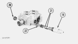
10. Remove line relief valve (19) from the valve housing.
11. Poppet and spring (21) will fall out of relief valve when it is removed.
12. Remove relief valve assembly (22) from the valve housing.
13. Remove plug (20) from the valve housing.
NOTE: Inspect all O-ring seals on all relief valves and plugs.
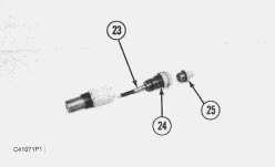
14. Remove adjusting nut (25), jam nut (24) and plunger (23) from the body of the line relief valve.
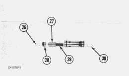
15. Remove circlips (26) and (30) from the relief valve.
16. Remove plunger end (28), poppet plunger (27) and spring (29) from the relief valve.
Assemble Hoist Control Valve
1. Install spring (29), poppet plunger (27) and plunger end (28) in the relief valve.
2. Install circlips (26) and (30) on the relief valve.
3. Install plunger (23) jam nut (24) and adjusting nut (25) in the body of the line relief valve.
4. Install plug (20) in the housing.
5. Install relief valve assembly (22) in the valve housing.
6. Make sure poppet and spring (21) is installed in the relief valve assembly.
 7. Install line relief valve (19) in the valve housing.
8. Install seals and spacer (10), relief valve sleeve (15), seal and spacer (11), cover (16), spring check valve (12), detent cap (17), poppet (13), spring and spring retainers (18) and cover plate (14) on the main control valve spool.
9. Install retainer ring (9) from the cover plate.
10. Install main control valve spool assembly (7) in the valve housing.
7. Install line relief valve (19) in the valve housing.
8. Install seals and spacer (10), relief valve sleeve (15), seal and spacer (11), cover (16), spring check valve (12), detent cap (17), poppet (13), spring and spring retainers (18) and cover plate (14) on the main control valve spool.
9. Install retainer ring (9) from the cover plate.
10. Install main control valve spool assembly (7) in the valve housing.
11. Install bolts (4) from cover.
12. Install boot (3) from cover.
13. Install flange (2).
14. Connect line (1) to the relief valve.
End By:
a. install hoist control valve
Copyright 1993 - 2020 Caterpillar Inc. All Rights Reserved. Private Network For SIS Licensees. Thu Feb 13 07:28:43 UTC+0800 2020
Shutdown SIS
Previous Screen
Product: ARTICULATED TRUCK
Model: D350D ARTICULATED TRUCK 9RF
Configuration: D25D, D30D, D350D ARTICULATED TRUCK 9RF00001-UP (MACHINE) POWERED BY 3306 ENGINE
Disassembly and Assembly
D25D,D30D AND D350D ARTICULATED DUMP TRUCKS VEHICLE SYSTEMS
Systems Protection Valve
SMCS - 5136-010; 5136-015; 5136-016
Remove & Install Systems Protection Valve
Air under pressure can cause personal injury. Before working on or around the air systems and components observe the following precautions.
a. Move the machine to a smooth and level location away from other working machines and personnel. Block the wheels and stop the engine.
b. Keep clear of actuator pushrods and linkages when the system is being operated in any way.
c. Do not remove plugs or lines, or disassemble components unless you are sure that all air pressure is exhausted.
d. Do not disassemble a component unless you have read and understood the correct procedures. Some components contain powerful springs. Injury can result from incorrect disassembly.
NOTE: Put identification on all lines, tubes and hoses for installation purposes.
Media Number -SENR8210-01 Publication Date -01/03/2005 Date Updated -05/12/2017
SENR82100006
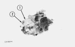
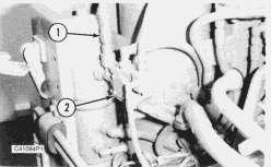
1. Disconnect all lines and tubes (1) from the systems protection valve. Unscrew or rotate systems protection valve (2) from the air dryer group.
NOTE: The following step is for the installation of the systems protection valve.
2. Put the systems protection valve (2) in position on the air dryer. Connect all lines and tubes (1) to the systems protection valve.
Disassemble Systems Protection Valve
Start By:
a. remove systems protection valve
Air under pressure can cause personal injury. Before working on or around the air systems and components observe the following precautions.
a. Move the machine to a smooth and level location away from other working machines and personnel. Block the wheels and stop the engine.
b. Keep clear of actuator pushrods and linkages when the system is being operated in any way.
c. Do not remove plugs or lines, or disassemble components unless you are sure that all air pressure is exhausted.
d. Do not disassemble a component unless you have read and understood the correct procedures. Some components contain powerful springs. Injury can result from incorrect disassembly.
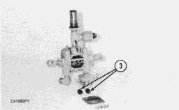
1. Remove screws (1) and plate (2) from the valve body.
2. Remove rubber pistons (3) and springs.
3. Turn the systems protection valve over and remove bolts (5) and cover (4).
4. Remove spring and piston assembly (6) from the protection valve body.
5. Disassemble spring and piston assembly by removing spring (10), piston inserts (12) and (9), piston (11), spring (7) and breather cap (8).
Assemble Systems Protection Valve
 1. Assemble spring and piston assembly by installing breather cap (8), spring (7), piston (11), piston inserts (9) and (12) and spring (10).
2. Install spring and piston assembly (6) in the protection valve body.
3. Turn the systems protection valve over and install cover (4) and bolts (5).
4. Install rubber pistons (3) and springs.
1. Assemble spring and piston assembly by installing breather cap (8), spring (7), piston (11), piston inserts (9) and (12) and spring (10).
2. Install spring and piston assembly (6) in the protection valve body.
3. Turn the systems protection valve over and install cover (4) and bolts (5).
4. Install rubber pistons (3) and springs.
a.
Copyright 1993 - 2020 Caterpillar Inc. All Rights Reserved. Private Network For SIS Licensees. Thu Feb 13 07:29:38 UTC+0800 2020
5.
Install plate (2) and screws (1) in the valve body.
End By:
install systems protection valve
Shutdown SIS
Previous Screen
Product: ARTICULATED TRUCK
Model: D350D ARTICULATED TRUCK 9RF
Configuration: D25D, D30D, D350D ARTICULATED TRUCK 9RF00001-UP (MACHINE) POWERED BY 3306 ENGINE
Disassembly and Assembly
D25D,D30D AND D350D ARTICULATED DUMP TRUCKS VEHICLE SYSTEMS
Relief Valve
SMCS - 5136-010; 5136-015; 5136-016
Remove & Install Relief Valve
Air under pressure can cause personal injury. Before working on or around the air systems and components observe the following precautions.
a. Move the machine to a smooth and level location away from other working machines and personnel. Block the wheels and stop the engine.
b. Keep clear of actuator pushrods and linkages when the system is being operated in any way.
c. Do not remove plugs or lines, or disassemble components unless you are sure that all air pressure is exhausted.
d. Do not disassemble a component unless you have read and understood the correct procedures. Some components contain powerful springs. Injury can result from incorrect disassembly.
Media Number -SENR8210-01 Publication Date -01/03/2005 Date Updated -05/12/2017 SENR82100007
1. To remove relief valve (1), unscrew or rotate it from the air dryer group.
2. Install the relief valve (1) on the air dryer in the reverse order.
Copyright 1993
Caterpillar
All Rights Reserved. Private Network For SIS Licensees. Thu Feb 13 07:30:34 UTC+0800 2020
- 2020
Inc.
Shutdown SIS
Previous Screen
Product: ARTICULATED TRUCK
Model: D350D ARTICULATED TRUCK 9RF
Configuration: D25D, D30D, D350D ARTICULATED TRUCK 9RF00001-UP (MACHINE) POWERED BY 3306 ENGINE
Disassembly and Assembly
D25D,D30D AND D350D ARTICULATED DUMP TRUCKS VEHICLE SYSTEMS
Shuttle Valve (Front And Rear)
SMCS - 5136-010; 5136-015; 5136-016
Remove & Install Shuttle Valve (Front And Rear)
Air under pressure can cause personal injury. Before working on or around the air systems and components observe the following precautions.
a. Move the machine to a smooth and level location away from other working machines and personnel. Block the wheels and stop the engine.
b. Keep clear of actuator pushrods and linkages when the system is being operated in any way.
c. Do not remove plugs or lines, or disassemble components unless you are sure that all air pressure is exhausted.
d. Do not disassemble a component unless you have read and understood the correct procedures. Some components contain powerful springs. Injury can result from incorrect disassembly.
Media Number -SENR8210-01 Publication Date -01/03/2005 Date Updated -05/12/2017
SENR82100008
Suggest:
If the above button click is invalid.
Please download this document first, and then click the above link to download the complete manual.
Thank you so much for reading

1. Remove rear shuttle valve by disconnecting lines (1), (2) and (4).
2. Remove bolt (3) to remove shuttle valve (5).
3. Remove front shuttle valve by disconnecting lines (6) and (8).
4. Rotate shuttle valve (7) to remove it.
NOTE: The following steps are for the installation of the front and rear shuttle valve.
5. Put front shuttle valve (7) in position and connect lines (6) and (8).
6. Put rear shuttle valve (5) and install bolt (3).
7. Connect lines (1), (2) and (4).
Disassemble & Assemble Shuttle Valve (Front Or Rear)
Start By:
a. remove shuttle valve (front or rear)
Air under pressure can cause personal injury. Before working on or around the air systems and components observe the following precautions.
a. Move the machine to a smooth and level location away from other working machines and personnel. Block the wheels and stop the engine.
b. Keep clear of actuator pushrods and linkages when the system is being operated in any way.
c. Do not remove plugs or lines, or disassemble components unless you are sure that all air pressure is exhausted.
d. Do not disassemble a component unless you have read and understood the correct procedures. Some components contain powerful springs. Injury can result from incorrect disassembly.