Service Repair Manual Models D25D, D30D, D350D ARTICULATED TRUCK
Shutdown SIS
Previous Screen
Product: ARTICULATED TRUCK
Model: D30D ARTICULATED TRUCK 3AJ
Configuration: D25D, D30D, D350D ARTICULATED TRUCK 3AJ00001-00414 (MACHINE) POWERED BY 3306 ENGINE
Disassembly and Assembly
D25D,D30D AND D350D ARTICULATED DUMP TRUCKS VEHICLE SYSTEMS

Primary Hydraulic Pump
SMCS - 5073-010; 5073-015; 5073-016
Remove & And Install Primary Hydraulic Pump
To prevent personal injury release the pressure from the hydraulic system before any lines are removed or disconnected.
NOTE: Put identification on all lines, hoses and tubes for installation purposes.
1. Drain the hydraulic fluid from the hydraulic tank.
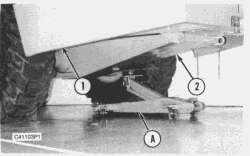
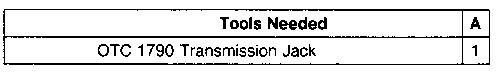
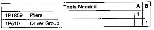
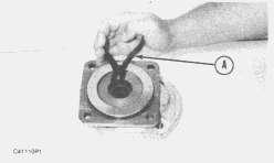
2. Put tool (A) in position under the guard (2).
Media Number -SENR8210-01 Publication Date -01/03/2005 Date Updated -05/12/2017
SENR82100014
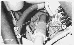
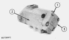
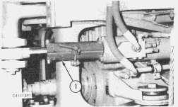
3. Remove two rear guard bolts (1) and then lower the guard (2) as far as possible.
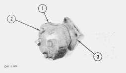
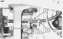
4. Disconnect hydraulic line (3) from the pump.
5. Remove two hose clamps (4) and then remove rubber hose section (5).
6. Fasten straps and a hoist to the primary hydraulic pump.
7. Disconnect bottom hose from the primary hydraulic pump.
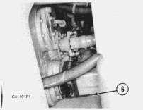
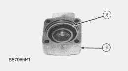
8. Remove the pump mounting bolts and then remove primary hydraulic pump (6).
9. Weight of the primary hydraulic pump is 34 Kg (75 lbs.).
NOTE: The following steps are for the installation of the primary hydraulic pump.
10. Put the primary hydraulic pump in position with the mounting bolts that hold it.
11. Install bottom hose to the primary hydraulic pump.
12. Install rubber hose section (5) with two hose clamps (4).
13. Connect hydraulic line (3) to the pump.
14. Raise the guard (2) with tool (A) and install two rear bolts (1).
15. Fill the hydraulic tank with hydraulic fluid to the correct level. See the MAINTENANCE MANUAL.
Disassemble Primary Hydraulic Pump
Start By:
a. remove primary hydraulic pump
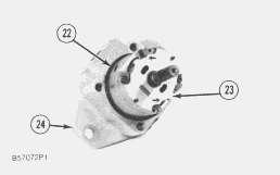
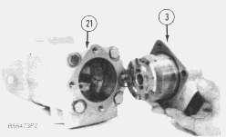
1. Clean the outside of the pump body and cover. Prior to disassembly, put reference marks between the end cover and center cover and the pump body. These marks will be reference for correct port relation at assembly.
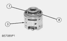
2. Remove bolts (1).
3. Remove cover (3). The cartridge will be removed when the cover is removed from hydraulic from hydraulic oil pump (2).
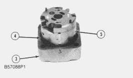
4. Remove O-ring seal (4) and cartridge (5).
5. Remove seal (6).
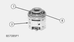
6. Remove back-up ring (7) and O-ring seal (8).
NOTE: Put an alignment mark across the components of the cartridge to give reference for the correct assembly.
NOTE: Make a note of the directions of the arrows at locations (X) and (Y) and the location of bolts (9) for correct assembly purposes. The arrows indicate the direction of rotation of the hydraulic oil pump. Bolts (9) are installed in the holes next to the arrows that show the direction of pump rotation.
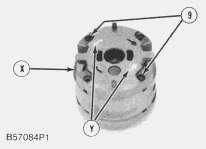
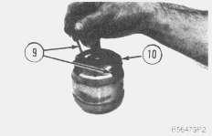
7. Remove bolts (9).
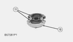
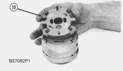
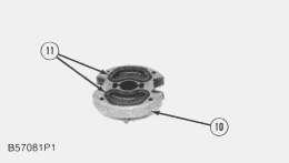
8. Remove plate (10).
9. Remove seal and retainers (11).
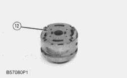
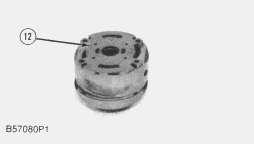
10. Remove plate (12).
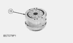
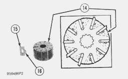
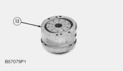
11. Remove ring (13).
12. Put a large rubber band around rotor (14) to hold the vanes and inserts in place. Remove rotor (14).
13. Remove vanes (15). Remove inserts (16). Check each vane (15) for wear or damage. Each vane must move freely in its opening (slot) in the rotor. Each insert must move freely in its vane.
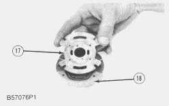
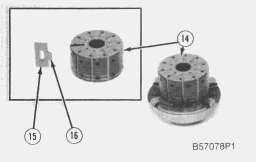
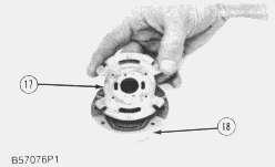
14. Remove plate (17).
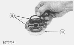
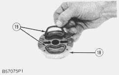
 15. Remove seal and retainers (19).
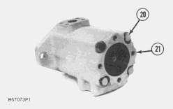
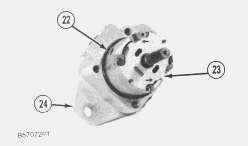
16. Remove bolts (20) and cover (21).
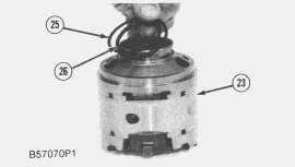
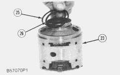
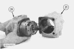
17. Remove O-ring seal (22), cartridge (23), and the seal below the cartridge in pump body (24).
18. Remove back-up (25) and O-ring seal (26).
15. Remove seal and retainers (19).
16. Remove bolts (20) and cover (21).
17. Remove O-ring seal (22), cartridge (23), and the seal below the cartridge in pump body (24).
18. Remove back-up (25) and O-ring seal (26).
NOTE: Put an alignment mark across the components of the cartridge to give reference for the correct assembly.
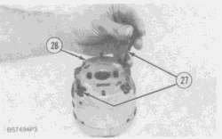
NOTE: Make a note of the directions of the arrows at locations (X) and (Y) and the location of bolts (27) for correct assembly purposes. The arrows indicate the direction of rotation of the hydraulic oil pump. Bolts (27) are installed in the holes next to the arrows that show the direction of pump rotation.
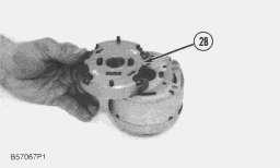
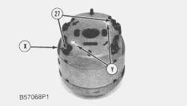
19. Remove bolts (27).
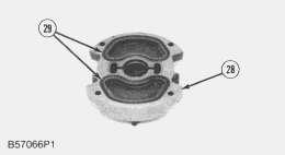
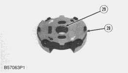
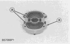
20. Remove plate (28).
21. Remove seal and retainers (29).
22. If necessary, remove bearing (46) with tooling (B).
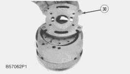
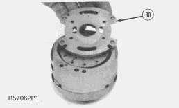
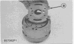
23. Remove plate (30).
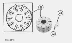
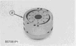
24. Remove ring (31).
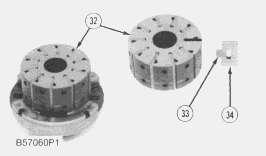
25. Put a large rubber band around rotor (32) to hold the vanes and inserts in place. Remove rotor (32).
26. Remove vanes (34). Remove inserts (33). Check each vane (34) for wear or damage. Each vane must move freely in its opening (slot) in the rotor. Each insert must move freely in its vane.
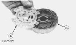
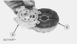
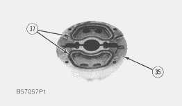
27. Remove plate (36).
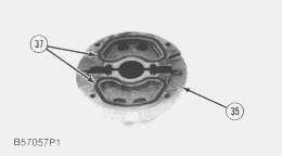

 28. Remove seal and retainers (37).
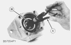
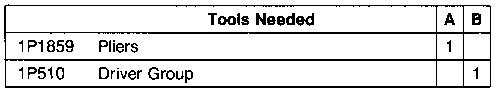
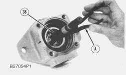
29. Remove retaining ring (38) with tool (A).
30. Use a press and tooling (B) and remove shaft (39).
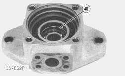
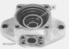
31. Remove retaining ring (40).
28. Remove seal and retainers (37).
29. Remove retaining ring (38) with tool (A).
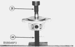
30. Use a press and tooling (B) and remove shaft (39).
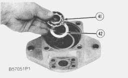
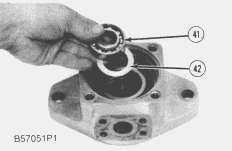
31. Remove retaining ring (40).
32. Remove bearing (41) and washer (42).
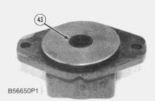
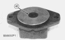
33. Remove two lip type seals (43).
Assemble Primary Hydraulic Pump
1. Clean all parts and inspect for wear or damage. Damage to any component of either cartridge group, except seals, will require replacement of the complete cartridge group. See Diagnosing Hydraulic Pump Failures (Form No. SEBD0501.
2. During assembly, all components must be installed in the correct direction of pump rotation. Pump rotation as seen from the drive end of the shaft is counterclockwise. Put clean oil on all parts during assembly.
3. Use tooling (B) and install lip type seal (43) in the pump body. Install the seal with the lip toward the pump shaft bearing.
4. Turn the pump body over. Use tooling (B) and install the inner lip type seal. Install the seal with the lip toward the pump shaft bearing.
 5. Install washer (42) and bearing (41).
6. Install retaining ring (40).
7. Put a piece of 2.54 cm (1 in.) diameter pipe that is 20.32 cm (8 in.) long in position against the inner race of the bearing (41). Use tooling (B), pipe (44) and a press and install shaft (39).
8. Use tooling (A) and install retaining ring (38).
5. Install washer (42) and bearing (41).
6. Install retaining ring (40).
7. Put a piece of 2.54 cm (1 in.) diameter pipe that is 20.32 cm (8 in.) long in position against the inner race of the bearing (41). Use tooling (B), pipe (44) and a press and install shaft (39).
8. Use tooling (A) and install retaining ring (38).
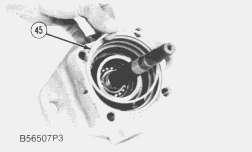
9. Install seal (45).
10. Install the O-ring seals in retainers (37). Install the retainers with the O-ring seals in contact with end plate (35).
11. Put plate (36) in position so the bronze side of the plate is toward the rotor.
NOTE: When vanes (34) are installed correctly, the rear edge of each vane is next to the balance opening (slot) in the rotor.
12. Install inserts (33) in vanes (34) and install them in rotor (32). The leading edge of each vane is toward the direction (arrow) of pump rotation. Each vane (34) must move freely in its slot in the rotor. Each insert (33) must move freely in vane (34).
13. Put a large rubber band around rotor (32) to hold the vanes and inserts in the rotor.
14. Put rotor (32) on plate (36). Be sure the leading edge of the vanes are in the direction of pump rotation. Remove the rubber band.
15. Put ring (31) in position. Make sure the arrow on the chamfer of the ring is in the same direction as the rotation of the rotor.
NOTICE
Make sure the notches on the outside diameter of the plates are in alignment. Make an alignment of these notches with the chamfers on ring (31).
16. Install plate (30) with the bronze face toward the rotor.
17. If it was necessary to remove bearing (46), use tooling (B) and a press and install bearing (46).
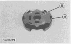
18. Install the O-ring seals in retainers with the O-ring seals in contact with end plate (28).
19. Put plate (28) in position.
20. Install bolts (27) in the holes nearest the arrows that are in the same direction as the arrow on ring (31). These arrows show the direction of pump rotation and must be assembled with the arrows in the same direction. Tighten bolts (27) to a torque of 10-12 N·m (88-106 lb.in.)
21. Install O-ring seal (26) and back-up ring (25). Install the O-ring seal on the rotor side of the groove.
22. Install cartridge (23). Put the cartridge in position so the pins in the plate are in alignment with the mounting holes in pump body (24) as shown.
23. Install O-ring seal (22).
24. Make sure the pins in the plate of the cartridge are in alignment with the cover (21). Install pump body (24) and cartridge (23) in cover (21). Install the bolts that hold the cover to the pump body.
25. Install the O-ring seal in retainers (19). Install the retainers with the O-ring seals in contact with end plate (18).
26. Put plate (17) in position so the bronze side of the plate is toward the rotor.
27. Install inserts (16) in vanes (15) and install them in rotor (14). The leading edge of each vane is toward the direction (arrow) of pump rotation. Each vane (15) must move freely in its slot in the rotor. Each insert (16) must move freely in vane (15).
28. Put a large rubber around rotor (14) to hold the vanes and inserts in the rotor.
29. Put rotor (14) on plate (17). Be sure the leading edge of the vanes are in the direction of pump rotation. Remove the rubber band.
30. Put ring (13) in position. Make sure the arrow on the chamfer of the ring is in the same direction as the rotation of the rotor.
33. Put plate (10) in position.
34. Install bolts (9) in the holes nearest the arrows that are in the same direction as the arrow on ring (13). These arrows show the direction of pump rotation and must be assembled with the arrows in the same direction.
 31. Install plate (12) with the bronze face toward the rotor.
32. Install the O-ring seals in retainers (11). Install the retainers with the O-ring seals in contact with end plate (10).
31. Install plate (12) with the bronze face toward the rotor.
32. Install the O-ring seals in retainers (11). Install the retainers with the O-ring seals in contact with end plate (10).
35. Install O-ring seal (8) and back-up ring (7). Install the O-ring seal on the rotor side of the groove.
36. Install seal (6).
37. Install cartridge (5). Put the cartridge in position so the pins in the plate are in alignment with the mounting holes in cover (3) as shown.
38. Install O-ring seal (4).
39. Make sure the pins in the plate of the cartridge are in alignment with the holes in cover (21). Install cover (3) and the cartridge in cover (21). Install the bolts that hold the covers together. Tighten the bolts to a torque of 95 ± 7 N·m (70 ± 5 lb.ft.).
End By:
a. install primary hydraulic pump
Copyright 1993 - 2020 Caterpillar Inc. All Rights Reserved. Private Network For SIS Licensees. Fri Feb 21 21:19:08 UTC+0800 2020
Shutdown SIS
Previous Screen
Product: ARTICULATED TRUCK
Model: D30D ARTICULATED TRUCK 3AJ
Configuration: D25D, D30D, D350D ARTICULATED TRUCK 3AJ00001-00414 (MACHINE) POWERED BY 3306 ENGINE
Disassembly and Assembly
D25D,D30D AND D350D ARTICULATED DUMP TRUCKS VEHICLE SYSTEMS
Supplemental Steering Pump
SMCS - 4306-010; 4306-015; 4306-017
Remove & Install Supplemental Steering Pump
To prevent personal injury release the pressure from the hydraulic system before any lines are removed or disconnected.
NOTE: The truck must be turned at least one half of its turning radius for removal of the supplemental steering pump.
Media Number -SENR8210-01 Publication Date -01/03/2005 Date Updated -05/12/2017
SENR82100015
1. Put lock steer assembly (1) in position on the steering cylinder.
Suggest:
If the above button click is invalid.
Please download this document first, and then click the above link to download the complete manual.
Thank you so much for reading

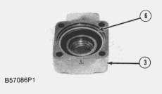
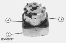
2. Disconnect hydraulic hoses (2) and (5) from the supplemental steering pump.
3. Remove nuts (4) and then remove supplemental steering pump (3).
NOTE: The following steps are for the installation of the supplemental steering pump.
4. Put the supplemental steering pump (3) in position with nuts (4).
5. Connect hydraulic hoses (2) and (5) to the supplemental steering pump.
6. Remove lock steer assembly (1) from the steering cylinder.
Disassemble Supplemental Steering Pump
Start By:
a. remove supplemental steering pump
1. Remove bolts (2) to make a separation between pump body (1) pump mounting flange (3).