Start By:
a. separate tractor and trailer
FLUID SPILLAGE CONTAINMENT
Care must be taken to ensure that fluids are contained during performance of inspection, maintenance, testing, adjusting and repair of the machine. Be prepared to collect the fluid with suitable containers before opening any compartment or disassembling any component containing fluids. Refer to "Tools And Shop Product Guide, NENG2500", for Tools and supplies suitable to collect and contain fluids in Caterpillar machines. Dispose fluids according to local regulations and mandates.
At operating temperature, the hydraulic oil tank is hot and under pressure. Hot oil can cause burns. Remove the breather filter cap only when the engine is stopped and the breather filter cap is cool enough to touch. Slowly loosen the breather filter cap to release any pressure in
the hydraulic tank. Be cautious of hot hydraulic oil when any lines are disconnected in the hydraulic system.
NOTE: Put identification on all lines, hoses, wires and tubes for installation purposes. Cap and plug all lines, hoses and tubes to prevent foreign material from entering the system.
NOTE: Drain all fluids in a suitable container for storage or disposal.
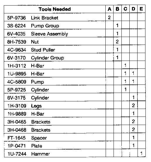
1. Use Tooling (D) to remove pin (1) from steering cylinder (2) at its pivot point (3) on hitch (4).

2. Repeat step number 1 for the opposite side of the hitch.
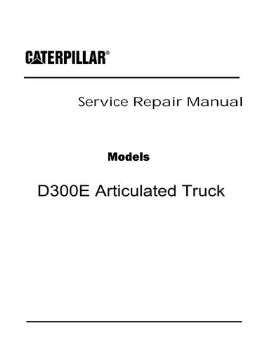
3. Remove bolt and retainer (5) from hitch (4).
4. Remove bolt and retainer (6) from lower hitch pin (7).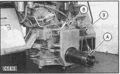


 5. Install Tool (A) and attach lifting straps (8) and safety chains (9) as shown and attach to a suitable lifting device.
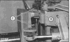
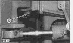
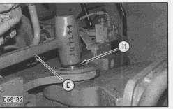
6. Remove bolt and retainer (10) from upper pivot pin (11) of hitch (4).
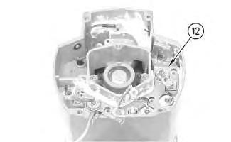
7. Loosen lock nuts (12) and remove thrust ring adjusting bolts (13).
8. Use Tooling (C) to remove the lower hitch pin (7).
5. Install Tool (A) and attach lifting straps (8) and safety chains (9) as shown and attach to a suitable lifting device.
6. Remove bolt and retainer (10) from upper pivot pin (11) of hitch (4).
7. Loosen lock nuts (12) and remove thrust ring adjusting bolts (13).
8. Use Tooling (C) to remove the lower hitch pin (7).
9. Use Tooling (C) to remove the upper hitch pin (11).
10.
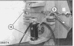
11. Use Tooling (B) to remove upper and lower spherical bearing (14), if necessary.
NOTE: The following steps are for the installation of the oscillating hitch.
 Remove hitch from the tractor. The weight of the hitch is 391 kg (860 lb).
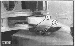
12. Using vacuum type grease position "V" seal with spacer (15) in lower hitch bearing cavity (16).
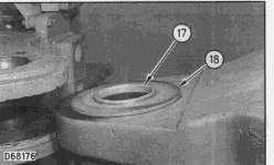
13. Position upper thrust ring (17) on upper pivot point hitch (18).
Remove hitch from the tractor. The weight of the hitch is 391 kg (860 lb).
12. Using vacuum type grease position "V" seal with spacer (15) in lower hitch bearing cavity (16).
13. Position upper thrust ring (17) on upper pivot point hitch (18).
16. Using tow people, move hitch in position on the tractor using car not to disrupt "V" ring (15) and upper thrust ring (17).


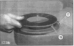 14. Position thrust ring (19) on top of thrust ring (17).
15. Using high vacuum grease position thrust ring (22) in bottom bearing cavity (21) of upper pivot hitch pin (20).
17. Install tapered pin (7) in lower pivot bearing (14) of hitch and mating with frame of tractor.
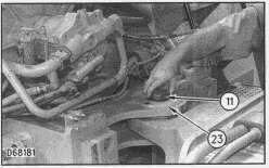
18. Install tapered pin (11) in upper bearing hitch pivot point (23).
14. Position thrust ring (19) on top of thrust ring (17).
15. Using high vacuum grease position thrust ring (22) in bottom bearing cavity (21) of upper pivot hitch pin (20).
17. Install tapered pin (7) in lower pivot bearing (14) of hitch and mating with frame of tractor.
18. Install tapered pin (11) in upper bearing hitch pivot point (23).
19. While impacting the tapered pin (11) with Tool (E), install bolt with retainer (10) and tighten to a torque of 360 N·m (270 lb ft).


NOTE: Continue to impact and tighten until impact no longer relaxes torque. Recheck after road test.
20. While impacting tapered pin (7) with Tool (E) install bolt with retainer (6) and tighten to a torque of 360 N·m (270 lb ft).
NOTE: Continue to impact and tighten until impact no longer relaxes torque. Recheck after road test.
End By:
a.
NOTE: Reference SEBU6903, April 1995 for final adjustment.


NOTE: Refer to the Operation & Maintenance Manual for all fluid capacities and the proper filling procedures.
Copyright 1993 - 2020 Caterpillar Inc. All Rights Reserved. Private Network For SIS Licensees.
21. Apply 9S-3263 Loctite to the threads and install bolt and retainer (5) under tractor hitch at tapered pin (7). 22. Using Tooling (D) install pin (1) from steering cylinder (2) at its pivot point (3) on hitch (4). connect tractor to trailerShutdown SIS
Previous Screen
Product: ARTICULATED TRUCK
Model: D300E ARTICULATED TRUCK 7FN
Configuration: D300E Articulated Truck 7FN00001-UP (MACHINE) POWERED BY 3306 Engine
Disassembly and Assembly
26SI Series Alternator
Alternator - Disassemble
SMCS - 1405-015
Disassembly Procedure
Table 1
Required Tools
Start By:
A. Remove the alternator. Refer to Disassembly and Assembly, "Alternator - Remove" for the machine that is being serviced.
Note: Cleanliness is an important factor. Before the disassembly procedure, the exterior of the component should be thoroughly cleaned. This will help to prevent dirt from entering the internal mechanism.
1. Remove the pulley nut, the washer, the pulley, and the fan.
Illustration 1 g00627790
2. Remove 4 screws (1). Remove plate (2) .

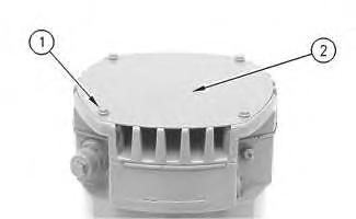
Illustration 2 g00627792
3. Remove 7 screws (3). Remove cover (4) .
Illustration 3 g00627794
4. Remove gasket (5) .

Illustration 4
g00627796
5. Remove 2 insulated screws (6). Remove the 3 leads.
Note: The regulator and the mounting plate are coated with dielectric grease. If the grease is removed, reapply the grease.

6. Remove nut (7) .
Illustration 5
7. Remove grounded mounting screw (8) .
8. Remove regulator (9) .
g00627804
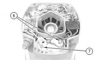
Illustration 6
g00627808
9. Remove mounting plate (10). The mounting plate may be stuck to the regulator.

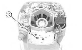
Illustration 7
g00627810
Note: The 3 output diodes (11) are located in heat sink (12). These diodes are identical in polarity. Diode (11) has red insulation on the wire. The 3 ground diodes (13) are located in housing (14). These diodes are identical in polarity. Diode (13) has black insulation on the wire.
10. Remove 3 nuts (15). Disconnect 3 stator phase leads. Disconnect 3 phase leads. Disconnect 6 diode leads.
Illustration 8
g00627820
11. Remove the screw and insulator (16). Disconnect capacitor lead (17) .
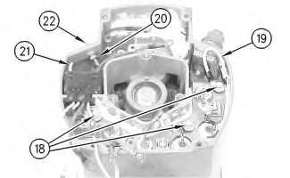
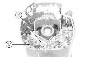
Illustration 9
g00627832
12. Remove the 3 screws and insulators (18). Disconnect wire (19) .
13. If the "R" terminal is used, remove the following components: nut (20), lead (21), the washer and terminal (21) .

Illustration 10 g00627840
14. Remove screw (23) and remove diode trio (24) .
15. Remove the nut and washer (25). Remove insulator (26). Remove alternator output terminal (27) .

16. Remove separator (28) .
Illustration 11
Note: Many of the alternator's internal components are covered with dielectric grease. If the grease is removed, reapply the grease.
Illustration 12
17. Remove the heat sink and diode assembly (12) from housing (14). Insulator (29) may be stuck to heat sink (12) .
g00627853 g00627855Illustration 13
g00628035
Note: Do not damage exposed stator windings or field windings. Bumping the windings or scraping the windings may break the insulation. Broken insulation may create a short circuit or a ground.
18. Remove 4 bolts (30). Carefully separate housing (31) from housing (14) .
Illustration 14
g00628037
19. Pull apart stator (32) and housing (14). Guide the stator leads and the grommet through the hole as the stator is removed from housing (14) .

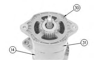
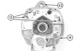
Illustration 15 g00628041
20. Remove 3 screws (33). Remove the coil and support (34) from housing (14). Guide the field leads and the grommet through the hole as the coil is removed from housing (14) .
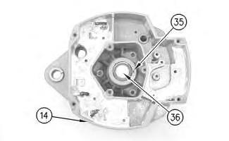

Illustration 16 g00628043
21. Position a small screwdriver in slot (35). Pry cap (36) from housing (14) .
Illustration 17 g00628057

Note: Do not strike the bearing. Shocks from striking the housing can cause damage.
22. Wipe the excess grease from the bearing well. Press bearing (37) into the housing. Remove the inner race.

Illustration 18 g00628063
23. Remove 4 screws (38) from housing (31) .
24. Lift rotor (39) and bearing (40) from housing (31) .
Illustration 19 g00628067
25. Pull bearing (40) from rotor (39) .
26. Pull retainer (41) from rotor (39) .
27. Pull collar (42) from rotor (39) .

Illustration 20
g00628068
Note: Do not strike the bushing. Shocks from striking the housing can cause damage.
28. Press bushing (43) from housing (14) .

Note: Do not strike the diodes. The shock of such an impact can damage the diodes. Use proper tools in order to press or pull the diodes from the mountings. As much as 890 N (200 lb) of force may be needed to remove a diode.
29. Remove 3 diodes (13) from housing (14) .
Illustration 21
30. Remove diode (11) from heat sink (12) .
Copyright 1993 - 2020 Caterpillar Inc. All Rights Reserved. Private Network For SIS Licensees.
g00628072
Sat Feb 15 01:20:22 UTC+0800 2020
Shutdown SIS
Previous Screen
Product: ARTICULATED TRUCK
Model: D300E ARTICULATED TRUCK 7FN
Configuration: D300E Articulated Truck 7FN00001-UP (MACHINE) POWERED BY 3306 Engine
Disassembly and Assembly
26SI Series Alternator
Alternator - Assemble
SMCS - 1405-016
Assembly Procedure
Note: Cleanliness is an important factor. Before assembly, all parts should be thoroughly cleaned in cleaning fluid. Allow the parts to air dry. Wiping cloths or rags should not be used to dry parts. Lint may be deposited on the parts which may cause later trouble. Inspect all parts. If any parts are worn or damaged, use new parts for replacement.
Note: Do not strike the diodes. The shock of such an impact can damage the diodes. Use proper tools in order to press the diodes in the mountings.
Suggest:
If the above button click is invalid.
Please download this document first, and then click the above link to download the complete manual.
Thank you so much for reading

Illustration 2
g00628068
Note: Do not strike the bushing. Shocks from striking the housing can cause damage.
2. Press bushing (43) in housing (14) .
3. Install 3 diodes (13) in housing (14) .
Illustration 3
4. Press collar (42) on rotor (39) .
5. Slide retainer (41) on rotor (39) .
6. Press bearing (40) on rotor (39) .
g00628067