Shutdown SIS
Previous Screen
Product: ARTICULATED TRUCK
Model: D250B ARTICULATED TRUCK 5WD
Configuration: D250B ARTICULATED DUMP TRUCK 5WD00001-00550 (MACHINE) POWERED BY 3306 ENGINE
Disassembly and Assembly
3304B and 3306B Engines for Caterpillar Built Machines
Fuel Injection Pump Housing - Disassemble
SMCS - 1253-015
Disassembly Procedure
Table 1
Required Tools Tool
A 1P-1860 Retaining Ring Pliers 1
Start By:
A. Disassemble the governor. Refer to Disassembly and Assembly, "Governor - Disassemble".
B. Remove the fuel injection pumps. Refer to Disassembly and Assembly, "Fuel Injection Pump - Remove".
NOTICE
Keep all parts clean from contaminants.
Contaminants may cause rapid wear and shortened component life.
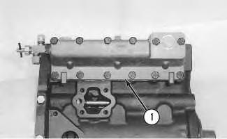
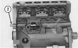
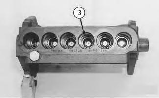 Illustration 1
g00456860
1. Remove cover (1) and the gasket.
Illustration 2 g00456923
2. Remove fuel rack (2) from the fuel injection pump housing.
Illustration 3
g00456924
Illustration 1
g00456860
1. Remove cover (1) and the gasket.
Illustration 2 g00456923
2. Remove fuel rack (2) from the fuel injection pump housing.
Illustration 3
g00456924
Note: If the original lifters are being reused in the fuel injection pump housing, place identification marks on the lifters in order to identify the locations.
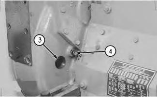
3. Remove lifters (3) from the fuel injection pump housing.
4. Position the fuel injection pump housing on wood blocks, as shown. Use Tool (A) in order to remove snap ring (4) .
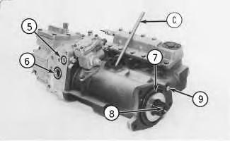
5. Use a soft hammer to push the camshaft toward the governor end of the fuel injection pump housing in order to loosen washer (5). Remove washer (5) .
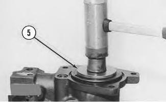
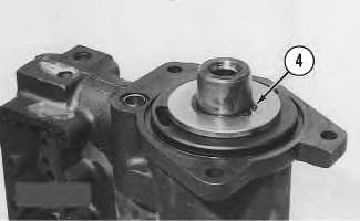 Illustration 4 g00456925
Illustration 5 g00456926
Illustration 4 g00456925
Illustration 5 g00456926
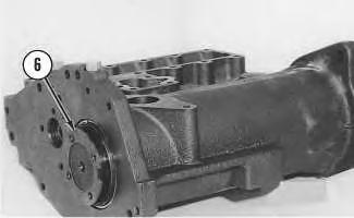
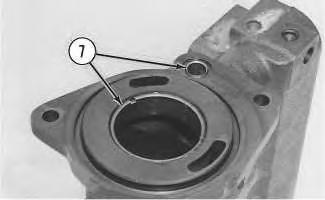
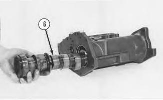
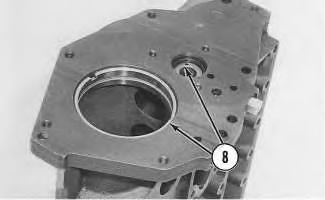 Illustration 6 g00456927
6. Remove camshaft (6) .
Illustration 7 g00456928
7. Remove bearings (7) from the drive end of the fuel injection pump housing.
Illustration 8 g00456930
8. Remove bearings (8) from the governor end of the fuel injection pump housing.
Illustration 6 g00456927
6. Remove camshaft (6) .
Illustration 7 g00456928
7. Remove bearings (7) from the drive end of the fuel injection pump housing.
Illustration 8 g00456930
8. Remove bearings (8) from the governor end of the fuel injection pump housing.
Shutdown SIS
Previous Screen
Product: ARTICULATED TRUCK
Model: D250B ARTICULATED TRUCK 5WD
Configuration: D250B ARTICULATED DUMP TRUCK 5WD00001-00550 (MACHINE) POWERED BY 3306 ENGINE
Disassembly and Assembly
3304B and 3306B Engines for Caterpillar Built Machines
Fuel Injection Pump Housing - Assemble
SMCS - 1253-016
Assembly Procedure Table 1
Required Tools
NOTICE
Keep all parts clean from contaminants.
Contaminants may cause rapid wear and shortened component life.
Note: Put clean engine oil on all parts before assembly. Ensure that all of the oil passages are clear.
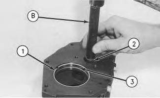
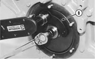
1. Use Tool (B) in order to install large bearing (1) in the governor end of the fuel injection pump housing. Bearing joint (3) should be facing toward the top of the fuel injection pump housing. Install the bearing so the bearing is 0.25 ± 0.20 mm (.010 ± .008 inch) below the surface of the fuel injection pump housing.
2. Use Tool (B) in order to install small bearing (2) in the governor end of the fuel injection pump so that Tool (B) is 7.16 ± 0.13 mm (.282 ± .005 inch) below the surface of the fuel injection pump housing.
g00457492
3. Use Tool (B) in order to install large bearing (4) in the drive end of the fuel injection pump housing. The bearing joint should be facing toward the top of the fuel injection pump housing. Install the bearing so the bearing is 1.00 ± 0.25 mm (.039 ± .010 inch) below the surface of the fuel injection pump housing.
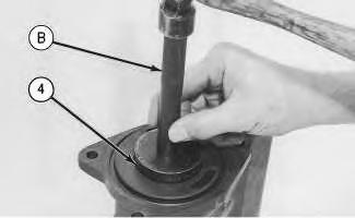 Illustration 1
g00457491
Illustration 2
Illustration 1
g00457491
Illustration 2
Illustration 3
g00457493
4. Install the plate of Tool (C) on the drive end of the fuel injection pump in order to install small bearing (5) for the rack. Use clean grease in order to hold the new driver for the rack bearing of Tool (C). Install the driver and the bearing in the plate. Ensure that the groove in the driver is aligned with the pin in the plate and use a hammer to push the bearing into position. The bearing will be installed to the correct depth when the shoulder of the driver is against the plate.
5. Remove Tool (C) from the fuel injection pump housing. The fuel rack bearing must be installed so that the fuel rack bearing is 0.25 ± 0.25 mm (.010 ± .010 inch) below the surface of the housing.
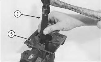
Illustration 4
6. Install camshaft (6) .
g00457494
7. Put the fuel injection pump housing upright, as shown. Place a wood block under the camshaft.
8. Put washer (7) over the end of the camshaft. Use Tool (B) and spacer (8) in order to push the washer against the seat on the camshaft. Spacer (8) has an inside diameter of 38.1 mm (1.50 inch) and a length of 31.75 mm (1.250 inch). The camshaft must have an end play of 0.18 ± 0.08 mm (.007 ± .003 inch) when the washer is pushed against the shoulder of the camshaft.
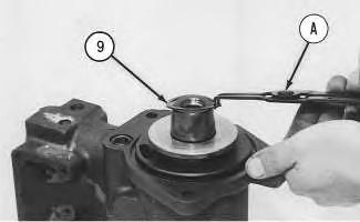
9. Use Tool (A) in order to install snap ring (9) .
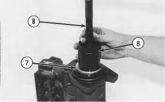 Illustration 5
g00458729
Illustration 6
g00457495
Illustration 5
g00458729
Illustration 6
g00457495
Note: Check the condition of the new lifters. Replace the lifters, if necessary. If the original lifters are being reused, place the lifters in the original locations. New lifters are identical, and the new lifters can be placed in any order.
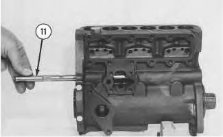
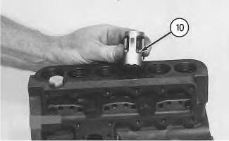 Illustration 7
g00458730
10. Install six lifters (10) in the fuel injection pump housing. Ensure that the groove in the lifter is aligned with the pin in the fuel injection pump housing.
Illustration 8
g00458731
11. Install rack (11). Ensure that the groove in the end of the rack is aligned with the ear (tab) of the fuel rack bearing that is at the drive end of the fuel injection pump housing.
Illustration 7
g00458730
10. Install six lifters (10) in the fuel injection pump housing. Ensure that the groove in the lifter is aligned with the pin in the fuel injection pump housing.
Illustration 8
g00458731
11. Install rack (11). Ensure that the groove in the end of the rack is aligned with the ear (tab) of the fuel rack bearing that is at the drive end of the fuel injection pump housing.
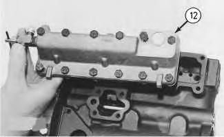
Illustration 9
12. Install the gasket and cover (12) .
End By:
g00458732
a. Assemble the governor. Refer to Disassembly and Assembly, "Governor - Assemble".
b. Install the fuel injection pumps. Refer to Disassembly and Assembly, "Fuel Injection Pump - Install".
Copyright 1993 - 2020 Caterpillar Inc. All Rights Reserved. Private Network For SIS Licensees.
Tue
Shutdown SIS
Previous Screen
Product: ARTICULATED TRUCK
Model: D250B ARTICULATED TRUCK 5WD
Configuration: D250B ARTICULATED DUMP TRUCK 5WD00001-00550 (MACHINE) POWERED BY 3306 ENGINE
Disassembly and Assembly
3304B and 3306B Engines for Caterpillar Built Machines
Fuel Injection Pump Housing and Governor - Install
SMCS - 1286-012
Installation Procedure Table 1
Required Tools
NOTICE
Keep all parts clean from contaminants.
Contaminants may cause rapid wear and shortened component life.
Note: The No. 1 piston must be set at the top center position (TC) in order to perform all of the timing procedures.
Note: The engine is seen from the flywheel end when the direction of the crankshaft rotation is given.
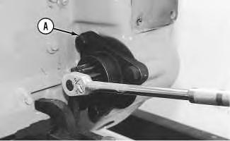
1. Remove the electric starting motor.
2. Install Tool (A) into the flywheel housing, as shown.
3. To find the TC position for the No. 1 piston, perform the following procedure:
a. Turn the flywheel clockwise or turn the flywheel in the opposite direction of the engine rotation for approximately 30 degrees. This removes all play from the timing gears.
Note: If you go past the bolt hole, repeat Step 3.a.
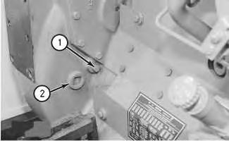
g00460248
b. Remove plugs (1) and (2) .
Illustration 1 g00460164 Illustration 2c. Turn the flywheel counterclockwise until a 3/8-16 X 3 1/2 NC bolt (4) can be installed in the flywheel through the hole in the flywheel housing. The No. 1 and No. 6 pistons are now at the TC position. Plug (2) was removed for viewing through inspection hole (3) .
Note: The No. 1 piston is on the compression stroke when the valves of the No. 1 cylinder are closed. The rocker arms for the inlet valves and for the exhaust valves must have slight side-to-side movement.
d. In order to check the position of the inlet and exhaust valves, remove the valve mechanism cover. Refer to Disassembly and Assembly, "Valve Mechanism CoverRemove and Install".
4. If the No. 1 piston is not on the compression stroke, remove bolt (4) and turn the flywheel for 360 degrees counterclockwise. Install bolt (4). The No. 1 piston is now at the TC position.
Typical example
Illustration 3 g00460252 Illustration 4 g004602585. Install Tool (C) in the fuel injection pump housing, as shown. Push on Tool (C) and turn fuel injection pump camshaft (8). When Tool (C) engages the groove (slot) in the camshaft, the fuel injection pump is in the TC position for the No. 1 piston.
Note: Check the condition of the O-ring seals. Replace the O-ring seals, if necessary.
6. Ensure that O-ring seals (5), (6), (7) and (9) are in position on the fuel injection pump housing and the governor. Put clean engine oil on the seals.
7. Attach a hoist and put the fuel injection pump housing and the governor in position on the timing gear plate and the oil manifold. Install three nuts (11), two bolts (10) and the washers. Ensure that Tool (C) remains in place.
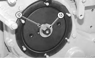
8. Install washer (12) with the large side outward. Install bolt (13) finger tight. Ensure that Tool (C) is in the notch in the camshaft of the fuel injection pump.
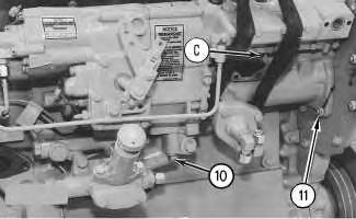 Illustration 5 g00460259
Illustration 6 g00460341
Illustration 5 g00460259
Illustration 6 g00460341
9. Install Tool (B) on the fuel pump drive gear. Apply 68 N·m (50 lb ft) of force to the fuel pump drive gear with timing bolt (3) in position in the flywheel and Tool (C) in position in the fuel system. Apply this force in a clockwise direction when the engine is viewed from the front. Use Tool (B) and a suitable torque wrench. Hold the 68 N·m (50 lb ft) of force on Tool (B) and torque the drive gear bolt to a torque of 270 ± 25 N·m (200 ± 18 lb ft). Remove Tool (B) and Tool (C) from the fuel pump and remove bolt (3) from the flywheel.
10. Use Tool (A) and turn the flywheel for two complete revolutions. When bolt (3) goes in the hole in the flywheel and Tool (C) is installed in the notch in the camshaft, the timing is correct.
11. Install plugs (1) and (2) .
12. Remove Tool (A). Install the electric starting motor.
13. Install the valve mechanism cover. Refer to Disassembly and Assembly, "Valve Mechanism Cover - Remove and Install".
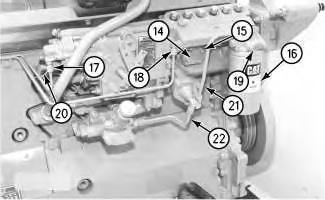
14. Put cover (14) and the gasket in position. Install four bolts (15) .
15. Put the fuel filter base, the gasket, and fuel filter (16) in position. Install two bolts (19) and the washers.
16. Install tube assemblies (21) and (22). Connect wire (20). Connect hoses (17) and (18) .
Illustration 9
g00589938
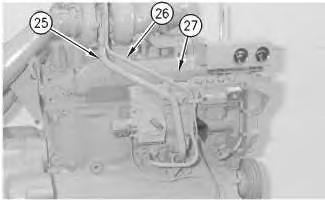
17. On the 3304B engines, install the strainer assembly in the turbocharger with the screen downward. Install the gasket, the oil inlet line and the bolts. Install the O-ring seal on oil drain line (25). Apply clean engine oil to the O-ring seal and install the gasket. Connect oil drain line (25) and install the bolts. Install the clamps on the oil line.
Illustration 10
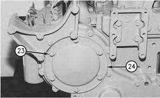
18. Put cover (24) in position. Install nuts (23) and six washers. Tighten nuts (23) to a torque of 27 ± 7 N·m (20 ± 5 lb ft).
End By: Install the fuel injection lines. Refer to Disassembly and Assembly, "Fuel Injection Lines - Remove and Install".
 g00460346
Shutdown SIS
Previous Screen
Product: ARTICULATED TRUCK
Model: D250B ARTICULATED TRUCK 5WD
Configuration: D250B ARTICULATED DUMP TRUCK 5WD00001-00550 (MACHINE) POWERED BY 3306 ENGINE
Disassembly and Assembly
3304B and 3306B Engines for Caterpillar Built Machines
Governor - Disassemble
SMCS - 1264-015
Disassembly Procedure
Table 1
Required Tools
Start By:
A. Remove the fuel injection pump housing and the governor. Refer to Disassembly and Assembly, "Fuel Injection Pump Housing and Governor - Remove".
Note: To remove the governor for the disassembly of the fuel injection pump housing, perform Steps 1, 2, 16, 22, 24, 25, 26, 27, 30, 32 and 34.
NOTICE
Keep all parts clean from contaminants.
Contaminants may cause rapid wear and shortened component life.
Suggest:
If the above button click is invalid.
Please download this document first, and then click the above link to download the complete manual.
Thank you so much for reading

1. Remove fuel ratio control (1) from governor (2) .
Note: Illustration 2 shows the fuel ratio control that is still connected.
2. Remove six bolts (3), two bolts (5), housing (4) and the gasket.
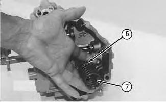
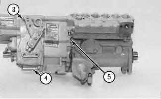
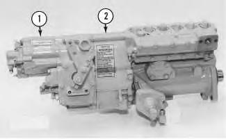 Illustration 1 g00453006
Illustration 2 g00453007
Illustration 3 g00453008
Illustration 1 g00453006
Illustration 2 g00453007
Illustration 3 g00453008