Shutdown SIS
Previous Screen
Product: WHEEL LOADER
Model: 950H WHEEL LOADER JAD
Configuration: 950H Wheel Loader JAD00001-UP (MACHINE) POWERED BY C7 Engine
Disassembly and Assembly
IT62H Integrated Toolcarrier and 950H and 962H Wheel Loaders Power Train
Gear Pump (Axle Oil Cooler) - Assemble
SMCS - 5073-016-AOC
Assembly Procedure
Table 1
Required Tools
Tool
A 1P-1858 Retaining Ring Pliers 1
Note: Cleanliness is an important factor. Before assembly, all parts should be thoroughly cleaned in cleaning fluid. Allow the parts to air dry. Wiping cloths or rags should not be used to dry parts Lint may be deposited on the parts which may cause later trouble. Inspect all parts. If any parts are worn or damaged, use new parts for replacement.
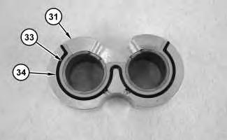
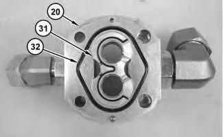

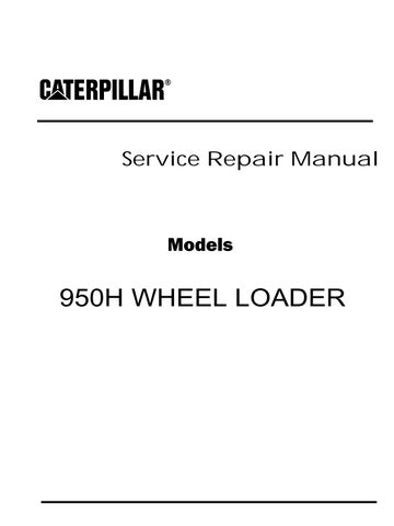
 Illustration 2
g01177072
2. Install bearing (31) and O-ring seal (32) on body (20) .
Illustration 3
g01177071
3. Install seal (30) in flange (29) .
Illustration 2
g01177072
2. Install bearing (31) and O-ring seal (32) on body (20) .
Illustration 3
g01177071
3. Install seal (30) in flange (29) .
Illustration 4
4. Install flange (29) on body (20) .
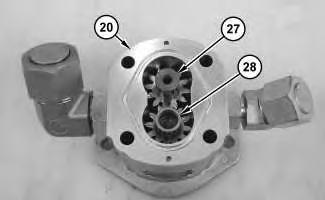
Illustration 5
5. Install gear (27) and shaft (28) in body (20)
Illustration 6
6. Use Tooling (A) to install retaining ring (26) .
7. Install key (25) .
 g01177070
g01177069
.
g01177067
g01177070
g01177069
.
g01177067


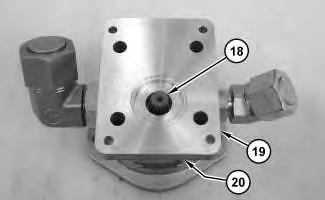 Illustration 7
g01177094
8. Install seal (23) and backup ring (24) on bearing (22) .
Illustration 8
g01177066
9. Install bearing (22) and O-ring seal (21) on body (20) .
Illustration 9
g01177064
10. Install flange (19) and coupling (18) on body (20) .
Illustration 7
g01177094
8. Install seal (23) and backup ring (24) on bearing (22) .
Illustration 8
g01177066
9. Install bearing (22) and O-ring seal (21) on body (20) .
Illustration 9
g01177064
10. Install flange (19) and coupling (18) on body (20) .
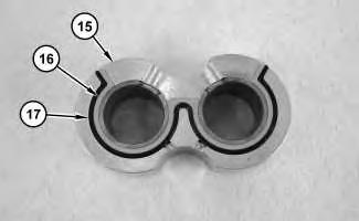
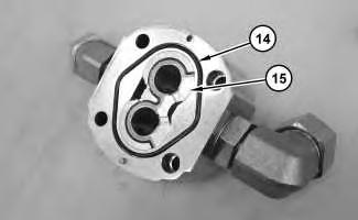
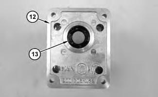 Illustration 10
g01177089
11. Install seal (16) and backup ring (17) on bearing (15) .
Illustration 11
g01177063
12. Install O-ring seal (14) and bearing (15) .
Illustration 10
g01177089
11. Install seal (16) and backup ring (17) on bearing (15) .
Illustration 11
g01177063
12. Install O-ring seal (14) and bearing (15) .
Illustration 12
13. Install seal (13) in flange (12) .
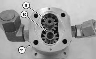

Illustration 13
Illustration 14
g01177062 g01177059 14. Install flange (12) on body (11) . g01177058 15. Install gear (9) and shaft (10) in body (11) .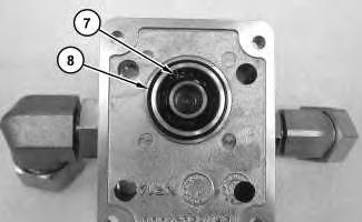

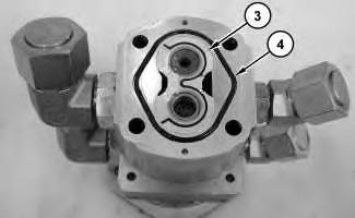 Illustration 15
g01177057
16. Use Tooling (A) to install retaining ring (7) .
17. Install O-ring seal (8) .
Illustration 16
g01177056
18. Install seal (5) and backup ring (6) in bearing (3) .
Illustration 17
g01177055
Illustration 15
g01177057
16. Use Tooling (A) to install retaining ring (7) .
17. Install O-ring seal (8) .
Illustration 16
g01177056
18. Install seal (5) and backup ring (6) in bearing (3) .
Illustration 17
g01177055
19. Install bearing (3) and O-ring seal (4) .
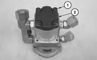
20. Install cover (2) and bolts (1) .
End By: Install the axle oil cooler pump and the clutch. Refer to Disassembly and Assembly, "Axle Oil Cooler Pump and Clutch - Remove and Install".
Illustration 18 g01177054Shutdown SIS
Previous Screen
Product: WHEEL LOADER
Model: 950H WHEEL LOADER JAD
Configuration: 950H Wheel Loader JAD00001-UP (MACHINE) POWERED BY C7 Engine
Disassembly and Assembly
IT62H Integrated Toolcarrier and 950H and 962H Wheel Loaders Power Train
Axle Oil Cooler Pump and Clutch - Install
SMCS - 5073-012-AOC
Installation Procedure Table 1
Required Tools
Note: Cleanliness is an important factor. Before assembly, all parts should be thoroughly cleaned in cleaning fluid. Allow the parts to air dry. Wiping cloths or rags should not be used to dry parts. Lint may be deposited on the parts which may cause later trouble. Inspect all parts. If any parts are worn or damaged, use new parts for replacement.
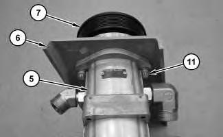
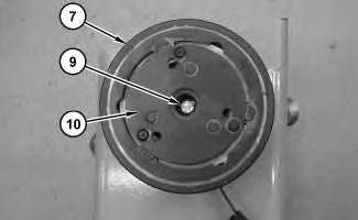
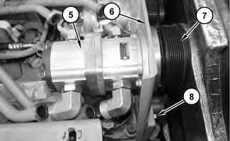 Illustration 1
g01177313
1. Connect clutch assembly (7), bracket assembly (6), and axle oil cooler pump (5) with bolts (11) .
Illustration 2
g01177312
2. Install clutch drive (10) and bolt (9) to clutch assembly (7) .
Illustration 3
g01177311
Illustration 1
g01177313
1. Connect clutch assembly (7), bracket assembly (6), and axle oil cooler pump (5) with bolts (11) .
Illustration 2
g01177312
2. Install clutch drive (10) and bolt (9) to clutch assembly (7) .
Illustration 3
g01177311
3. Position clutch assembly (7), bracket assembly (6), and axle oil cooler pump (5), as shown.
4. Install bolts (8) .
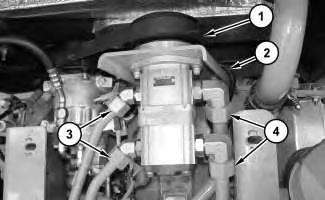
Illustration 4 g01177310
5. Connect harness assembly (2), tube assemblies (3), and tube assemblies (4) .
6. Install belt (1). Refer to Operation and Maintenance Manual, "Belts - Inspect / Adjust / Replace".
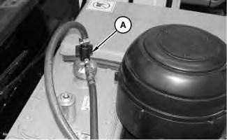
Illustration 5 g01165944
7. Remove Tooling (A) from the hydraulic tank.
8. Turn the battery disconnect switch to the ON position. Copyright 1993 - 2020 Caterpillar Inc.
Previous Screen
Product: WHEEL LOADER
Model: 950H WHEEL LOADER JAD
Configuration: 950H Wheel Loader JAD00001-UP (MACHINE) POWERED BY C7 Engine
Disassembly and Assembly
C7
Engines for Caterpillar Built Machines
Fuel Filter Base - Remove and Install
SMCS - 1262-010
Removal Procedure
Fuel leaked or spilled onto hot surfaces or electrical components can cause a fire. To help prevent possible injury, turn the start switch off when changing fuel filters or water separator elements. Clean up fuel spills immediately.
NOTICE
Care must be taken to ensure that fluids are contained during performance of inspection, maintenance, testing, adjusting and repair of the product. Be prepared to collect the fluid with suitable containers before opening any compartment or disassembling any component containing fluids.
Refer to Special Publication, NENG2500, "Caterpillar Tools and Shop Products Guide" for tools and supplies suitable to collect and contain fluids on Caterpillar products.
Dispose of all fluids according to local regulations and mandates.
Illustration 1
1. Disconnect hose assembly (1) and hose assembly (3) .
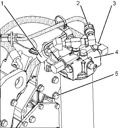
2. Disconnect harness assembly (2) .
3. Remove bolts (5) and fuel filter base (4) .
Installation Procedure
NOTICE
Keep all parts clean from contaminants.
Contaminants may cause rapid wear and shortened component life.
1. Position fuel filter base (4) on the engine.
2. Install bolts (5) .
3. Connect harness assembly (2) .
4. Connect hose assembly (3) and hose assembly (1) .
Illustration 2 g01152090Previous Screen
Product: WHEEL LOADER
Model: 950H WHEEL LOADER JAD
Configuration: 950H Wheel Loader JAD00001-UP (MACHINE) POWERED BY C7 Engine
Disassembly and Assembly
C7
Engines for Caterpillar Built Machines
Fuel Transfer Pump - Remove
SMCS - 1256-011
Removal Procedure Table 1 Required Tools
Start By:
a. Remove the unit injector hydraulic pump. Refer to Disassembly and Assembly, "Unit Injector Hydraulic Pump - Remove".
Note: Tooling (A) is required for replacement of the fuel transfer pump.
NOTICE
Care must be taken to ensure that fluids are contained during performance of inspection, maintenance, testing, adjusting, and repair of the product. Be prepared to collect the fluid with suitable containers before opening any compartment or disassembling any component containing fluids.
Refer to Special Publication, NENG2500, "Dealer Service Tool Catalog" for tools and supplies suitable to collect and contain fluids on Cat® products.
Dispose of all fluids according to local regulations and mandates.
1. Mount the unit injector hydraulic pump in a vertical position on a work bench.
Note: Failure to maintain a vertical position results in misalignment of the internal components.
2. Remove bolts (3).
3. Remove tie bolt (1) that is located in the top left corner of the pump first.
4. Replace tie bolt (1) with Tooling (A).
Note: Tooling (A) has an undersized bolt head. Tooling (A) will prevent the body of the unit injector hydraulic pump from separating during service.
5. Tighten Tooling (A) to a torque of 10 N·m (89 lb in).
6. Start with tie bolt (4) in the lower left corner and remove the remainder of the bolts from fuel transfer pump (2).
7. Remove fuel transfer pump (2).
Previous Screen
Product: WHEEL LOADER
Model: 950H WHEEL LOADER JAD
Configuration: 950H Wheel Loader JAD00001-UP (MACHINE) POWERED BY C7 Engine
Disassembly and Assembly
C7
Engines for Caterpillar Built Machines
Fuel Transfer Pump - Install
SMCS - 1256-012
Installation Procedure Table 1 Required Tools
NOTICE
Keep all parts clean from contaminants.
Contaminants may cause rapid wear and shortened component life.
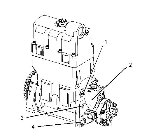
Illustration 1
g01123057
1. Position fuel transfer pump (2) on the unit injector hydraulic pump. Be sure to align the drive tang of the fuel transfer pump to the drive slot in the end of the pump shaft.
2. Install tie bolts (4). Tighten the bolts to a snug fit.
3. Remove Tooling (A) that is located in the upper left hole and install remaining tie bolt (1) to a snug fit.
4. Install bolts (3) for fuel transfer pump (2). Tighten the bolts to a snug fit.
5. Start in the lower left corner of the unit injector hydraulic pump and tighten tie bolts (4) to a torque of 28 ± 2 N·m (21 ± 1 lb ft) in a crisscross pattern. Torque the bolts again.
6. Tighten bolts (3) to a torque of 8.0 ± 0.4 N·m (71 ± 4 lb in).
End By:
a. Install the unit injector hydraulic pump. Refer to Disassembly and Assembly, "Unit Injector Hydraulic Pump - Install".
Copyright 1993 - 2020 Caterpillar Inc.
Rights Reserved.
Previous Screen
Product: WHEEL LOADER
Model: 950H WHEEL LOADER JAD
Configuration: 950H Wheel Loader JAD00001-UP (MACHINE) POWERED BY C7 Engine
Disassembly and Assembly
C7
Engines for Caterpillar Built Machines
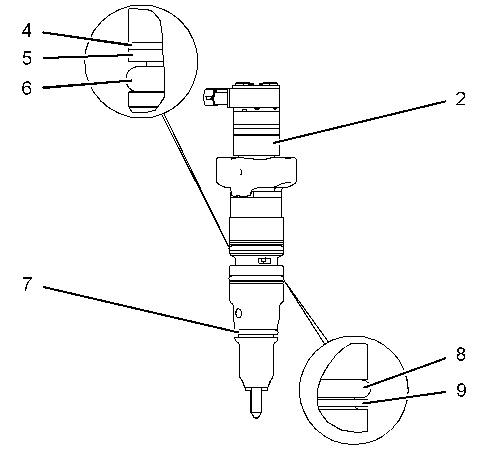
Unit Injector - Remove
SMCS - 1290-011
Removal Procedure
Table 1 Required Tools
Start By:
A. Remove the valve mechanism cover. Refer to Disassembly and Assembly, "Valve Mechanism Cover - Remove and Install".
NOTICE
Keep all parts clean from contaminants.
Contaminants may cause rapid wear and shortened component life.
Illustration 1
g03007076
1. Drain the coolant, oil, and fuel from the cylinder head. Remove the oil galley plug (1) , fuel galley plug (2) , and coolant line (3) .
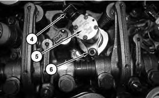
Illustration 2
2. Disconnect harness assembly (4) .
g03028024
3. Remove socket head bolts (6) from unit injector (5) .
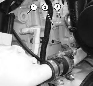
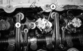
Illustration 3
g03028041
4. Install Tooling (A) . Use Tooling (A) to remove unit injector (5) .
Note: Do not use a wire brush on the tip of the unit injector. Damage to the unit injector will occur.
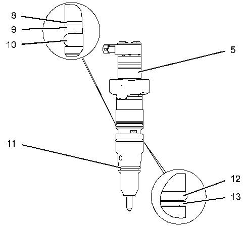
Illustration 4
g03009616
5. Remove O-ring seal (10) , O-ring seal (11) , and O-ring seal (12) from unit injector (5) .
6. Remove backup ring (8) , backup ring (9) , and backup ring (13) .
Previous Screen
Product: WHEEL LOADER
Model: 950H WHEEL LOADER JAD
Configuration: 950H Wheel Loader JAD00001-UP (MACHINE) POWERED BY C7 Engine
Disassembly and Assembly
Unit Injector - Install
SMCS - 1290-012
Installation Procedure
NOTICE
Keep all parts clean from contaminants.
Contaminants may cause rapid wear and shortened component life.
1. Evacuate as much fuel and oil as possible from the cylinder head before installing the unit injector. Several evacuations may be necessary. Use Tooling (G) to remove the fuel and oil from the cylinder.
Note: Tooling (L) is available to clean loose material from the sleeve bore and the cylinder.
2. Clean the carbon from the sleeve, the sleeve bore, and the end of the unit injector. Clean the carbon from the seat area that is inside of the cylinder head. A fine grade of Tooling (D) is preferred. Clean the carbon from the cylinder head and sleeves. If the sleeve of the unit injector has been removed from the engine, use Tooling (H) to remove the carbon. If the sleeve of the unit injector is installed in the engine, use Tooling (J) to remove the carbon.
The following procedure is the preferred method of cleaning the sleeve bore.
Place a 38 mm (1.5 inch) square piece of Scotch Brite material on the end of Tooling (K) . Twist Tooling (K) with Tooling (M) against the lower surface of the sleeve bore.
The surface should be cleaned until the surface is smooth and shiny. The entire sleeve bore should be cleaned in order to remove any loose carbon particles.
Note: Tooling (L) is available to clean loose material from the sleeve bore and the cylinder.
NOTICE
The correct procedures and tooling specifications must always be used. Failure to follow any of the procedures may result in damage, malfunction, or possible engine failure.
NOTICE
The O-ring seals and the backup rings must be installed in the correct orientation. Damaged seals will result in excessive oil consumption or excessive leakage under the valve cover. Use care to prevent nicks or damage to the seals.
Suggest:
If the above button click is invalid.
Please download this document first, and then click the above link to download the complete manual.
Thank you so much for reading

3. Lubricate O-ring seal (6) , O-ring seal (7) , O-ring seal (8) , and the sleeve bore of the unit injector sparingly with clean engine oil.
4. Use Tooling (E) and Tooling (F) to install backup ring (4) , backup ring (5) , O-ring seal (6) , backup ring (9) , and O-ring seal (8) .
5. Install O-ring seal (7) .
6. Lubricate the O-ring seals and the backup rings on the unit injector with clean engine oil before installation.
Note: Proper installation of the unit injector is important. Damage to the upper highpressure seals can cause excessive oil leakage under the valve cover. The damage may cause the engine not to start due to a low actuation pressure. Damage to the lower high-pressure seals may allow high-pressure oil to leak into the fuel supply passage resulting in excessive oil consumption.
Note: Do not hit or strike the unit injector during installation.
7. Record the serial number for the injector and the confirmation code for the injector. When a new unit injector is installed, the E-Trim value must be programmed into the Engine Control Module. For more information, refer to Troubleshooting, "Injector CodeCalibrate".