Previous Screen
Product: COMPACT WHEEL LOADER
Model: 906 COMPACT WHEEL LOADER MER
Configuration: 906 Wheel Loader MER00001-UP (MACHINE) POWERED BY 3044C Engine
Disassembly and Assembly
906 and 908 Compact Wheel Loaders 3044C Engine Supplement
Water Pump - Remove and Install
SMCS - 1361-010
Removal Procedure
At operating temperature, the engine coolant is hot and under pressure.
Steam can cause personal injury.
Check the coolant level only after the engine has been stopped and the fill cap is cool enough to touch with your bare hand.
Remove the fill cap slowly to relieve pressure.
Cooling system conditioner contains alkali. Avoid contact with the skin and eyes to prevent personal injury.
NOTICE
Care must be taken to ensure that fluids are contained during performance of inspection, maintenance, testing, adjusting and repair of the product. Be prepared to collect the fluid with suitable containers before opening any compartment or disassembling any component containing fluids.
Refer to Special Publication, NENG2500, "Caterpillar Tools and Shop Products Guide" for tools and supplies suitable to collect and contain fluids on Caterpillar products.
Dispose of all fluids according to local regulations and mandates.
1. Open the hood.
2. Turn the battery disconnect switch to the OFF position.
3. Drain the coolant from the cooling system into a suitable container for storage or disposal. Refer to Operation and Maintenance Manual for the correct procedure.
4. Remove bolts (1) and cover (2) .
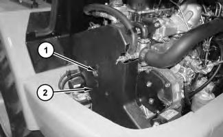 Illustration 1
g01318369
Illustration 1
g01318369
7. Remove bolts (10) and remove water pump (11) .
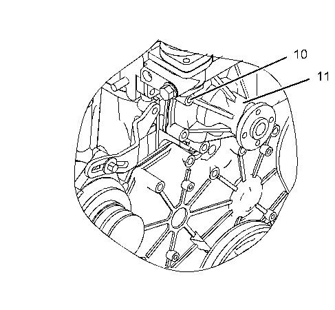
Illustration 5 g01037949
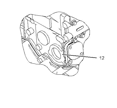
8. Remove gasket (12) .
Installation Procedure
Note: Cleanliness is an important factor. Before assembly, all parts should be thoroughly cleaned in cleaning fluid. Allow the parts to air dry. Wiping cloths or rags should not be used to dry parts. Lint may be deposited on the parts which may cause later trouble. Inspect all parts. If any parts are worn or damaged, use new parts for replacement.
Illustration 6 g01037949
1. Install new gasket (12) .
Illustration 9
g01037886
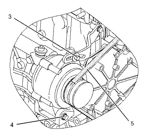
4. Rotate the alternator in order to tighten belt (5). Tighten bolts (3) and (4). Refer to Operation and Maintenance Manual, "Belts - Inspect/Adjust/Replace" for additional information.
Illustration 10
5. Install cover (2) and bolts (1) .
g01318369
6. Fill the cooling system with coolant. Refer to Operation and Maintenance Manual for the correct procedure.
7. Turn the disconnect switch to the ON position.
8. Close the hood.
1993 - 2019 Caterpillar Inc.
Shutdown SIS
Previous Screen
Product: COMPACT WHEEL LOADER
Model: 906 COMPACT WHEEL LOADER MER
Configuration: 906 Wheel Loader MER00001-UP (MACHINE) POWERED BY 3044C Engine
Disassembly and Assembly
906 and 908 Compact Wheel Loaders 3044C Engine Supplement
Gear Motor (Hydraulic Fan) - Remove and Install
SMCS - 1386-010-GT; 5061-010-HFN
Removal Procedure
Personal injury can result from hydraulic oil pressure and hot oil.
Hydraulic oil pressure can remain in the hydraulic system after the engine has been stopped. Serious injury can be caused if this pressure is not released before any service is done on the hydraulic system.
Make sure all of the work tools have been lowered to the ground, and the oil is cool before removing any components or lines. Remove the oil filler cap only when the engine is stopped, and the filler cap is cool enough to touch with your bare hand.
NOTICE
Care must be taken to ensure that fluids are contained during performance of inspection, maintenance, testing, adjusting, and repair of the machine. Be prepared to collect the fluid with suitable containers before opening any compartment or disassembling any component containing fluids.
Refer to Special Publication, NENG2500, "Caterpillar Tools and Shop Products Guide"for tools and supplies to collect and contain fluids in Caterpillar machines.
Dispose of all fluids according to local regulations.
Note: Put identification marks on all lines, on all hoses, on all wires, and on all tubes for installation purposes. Plug all lines, hoses, and tubes. This helps to prevent fluid loss and this helps to keep contaminants from entering the system.
1. Open the hood.
2. Turn the disconnect switch to the OFF position.
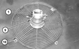
3. Disconnect hose assemblies (2) from gear motor (1) .
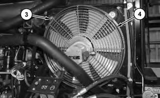
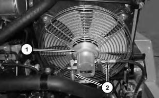 Illustration 1
g01318700
Illustration 2
g01318701
4. Remove bolts (3) and remove fan assembly (4) .
Illustration 1
g01318700
Illustration 2
g01318701
4. Remove bolts (3) and remove fan assembly (4) .
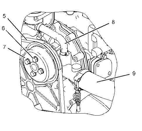
5. Remove bolts (5) and fan (6) .
6. Remove bolts (7) and coupling (8) .
7. Remove bolts (9) and remove gear motor (1) from fan guard (10) .
Installation Procedure
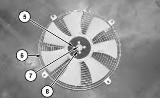 Illustration 3
g01318702
Illustration 4
g01318704
Illustration 5
g01318704
1. Install gear motor (1) to fan guard (10) and install bolts (9) .
Illustration 6
g01318702
2. Install coupling (8) and bolts (7) .
3. Install fan (6) and bolts (5) .
Illustration 7
g01318701
Illustration 3
g01318702
Illustration 4
g01318704
Illustration 5
g01318704
1. Install gear motor (1) to fan guard (10) and install bolts (9) .
Illustration 6
g01318702
2. Install coupling (8) and bolts (7) .
3. Install fan (6) and bolts (5) .
Illustration 7
g01318701
4. Install fan assembly (4) and bolts (3) .
5. Connect hose assemblies (2) to gear motor (1) .
6. Turn the disconnect switch to the ON position.
7. Close the hood.
1993 - 2019
Illustration 8 g01318700Shutdown SIS
Previous Screen
Product: COMPACT WHEEL LOADER
Model: 906 COMPACT WHEEL LOADER MER
Configuration: 906 Wheel Loader MER00001-UP (MACHINE) POWERED BY 3044C Engine
Disassembly and Assembly
906 and 908 Compact Wheel Loaders 3044C Engine Supplement
Hydraulic Oil Cooler - Remove and Install
SMCS - 1374-010
Removal Procedure
Personal injury can result from hydraulic oil pressure and hot oil.
Hydraulic oil pressure can remain in the hydraulic system after the engine has been stopped. Serious injury can be caused if this pressure is not released before any service is done on the hydraulic system.
Make sure all of the work tools have been lowered to the ground, and the oil is cool before removing any components or lines. Remove the oil filler cap only when the engine is stopped, and the filler cap is cool enough to touch with your bare hand.
NOTICE
Care must be taken to ensure that fluids are contained during performance of inspection, maintenance, testing, adjusting, and repair of the machine. Be prepared to collect the fluid with suitable containers before opening any compartment or disassembling any component containing fluids.
Refer to Special Publication, NENG2500, "Caterpillar Tools and Shop Products Guide"for tools and supplies to collect and contain fluids in Caterpillar machines.
Dispose of all fluids according to local regulations.
Note: Put identification marks on all lines, on all hoses, on all wires, and on all tubes for installation purposes. Plug all lines, hoses, and tubes. This helps to prevent fluid loss and this helps to keep contaminants from entering the system.
1. Drain the hydraulic oil from the hydraulic oil cooler into a suitable container for storage or disposal. Refer to Operation and Maintenance Manual for the correct procedure.
2. Remove bolts (1) and grill (2) .
3. Raise the access door on the right side of the machine.
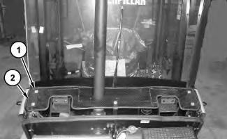
4. Remove two bolts (3). Remove brace (4) .
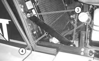 Illustration 1
g01319086
Illustration 2
g00641051
Illustration 1
g01319086
Illustration 2
g00641051
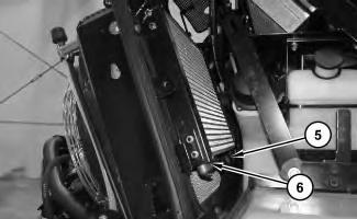
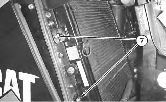
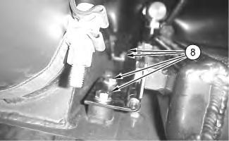 Illustration 3
g01319098
5. Loosen the clamps and disconnect hose (5) and hose (6) from the hydraulic oil cooler.
Illustration 4
g00641067
6. Remove two bolts (7) from the side of the hydraulic oil cooler.
Illustration 5
g00641443
This is a view from the top of the hydraulic oil cooler.
Illustration 3
g01319098
5. Loosen the clamps and disconnect hose (5) and hose (6) from the hydraulic oil cooler.
Illustration 4
g00641067
6. Remove two bolts (7) from the side of the hydraulic oil cooler.
Illustration 5
g00641443
This is a view from the top of the hydraulic oil cooler.
7. Remove four bolts (8) from the opposite side of the hydraulic oil cooler.
Illustration 6
g00641638
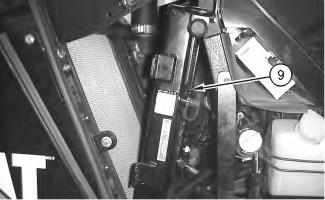
8. Move the top of hydraulic oil cooler (9) toward the cab of the machine.
9. Install a nylon strap and a suitable lifting device around the hydraulic oil cooler.
Illustration 7
g00641642
10. Remove hydraulic oil cooler (9). The weight of hydraulic oil cooler (9) is 20.4 kg (45 lb).
Installation Procedure
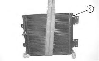 Illustration 8
g00641642
1. Install a nylon strap around hydraulic oil cooler (9) .
Illustration 9
g00641638
2. Place the hydraulic oil cooler (9) into position.
3. Move hydraulic oil cooler (9) into the upright position. Align hydraulic oil cooler (9) with the bolt holes.
Illustration 8
g00641642
1. Install a nylon strap around hydraulic oil cooler (9) .
Illustration 9
g00641638
2. Place the hydraulic oil cooler (9) into position.
3. Move hydraulic oil cooler (9) into the upright position. Align hydraulic oil cooler (9) with the bolt holes.
Illustration 10 g00641443
This is a view from the top of the hydraulic oil cooler.
4. Install washers and four bolts (8) through the hinged side of hydraulic oil cooler (9) .
Illustration 11 g00641067
5. Install washers and two bolts (7) on the opposite side of the hydraulic oil cooler.
Illustration 12
6. Connect hose (5) and hose (6) to the hydraulic oil cooler and tighten the clamps.
g01319098Illustration 13
g00641051
7. Install brace (4) in position. Secure brace (4) with the washers and two bolts (3) .
Illustration 14
8. Install grill (2) and bolts (1) .
g01319086
9. Fill the hydraulic oil tank with hydraulic oil. Refer to Operation and Maintenance Manual for the correct procedure.
Copyright 1993 - 2019 Caterpillar Inc.
All Rights Reserved. Private Network For SIS Licensees.
Wed Sep 11 22:57:24 UTC+0800 2019
Suggest:
If the above button click is invalid.
Please download this document first, and then click the above link to download the complete manual.
Thank you so much for reading

Previous Screen
Product: COMPACT WHEEL LOADER
Model: 906 COMPACT WHEEL LOADER MER
Configuration: 906 Wheel Loader MER00001-UP (MACHINE) POWERED BY 3044C Engine
Disassembly and Assembly
906 and 908 Compact Wheel Loaders 3044C Engine Supplement
Radiator - Remove and Install
SMCS - 1353-010
Removal Procedure
Start By:
A. Remove the hood. Refer to Disassembly and Assembly, "Hood - Remove and Install".
Personal injury can result from hydraulic oil pressure and hot oil.
Hydraulic oil pressure can remain in the hydraulic system after the engine has been stopped. Serious injury can be caused if this pressure is not released before any service is done on the hydraulic system.
Make sure all of the work tools have been lowered to the ground, and the oil is cool before removing any components or lines. Remove the oil filler cap only when the engine is stopped, and the filler cap is cool enough to touch with your bare hand.
NOTICE
Care must be taken to ensure that fluids are contained during performance of inspection, maintenance, testing, adjusting, and repair of the machine. Be prepared to collect the fluid with suitable containers before opening any compartment or disassembling any component containing fluids.