
Service
Shutdown SIS
Previous Screen
Product: BACKHOE LOADER
Model: 428D BACKHOE LOADER BMT
Configuration: 428D Backhoe Loader BMT01618-03227 (MACHINE) POWERED BY 3054 Engine
Disassembly and Assembly
416D, 420D, 424D, 428D, 430D, 432D, 438D and 442D Backhoe Loaders Machine Systems
Steering Metering Pump - Remove
SMCS - 4312-011
Removal Procedure
Personal injury can result from hydraulic oil pressure and hot oil.
Hydraulic oil pressure can remain in the hydraulic system after the engine has been stopped. Serious injury can be caused if this pressure is not released before any service is done on the hydraulic system.
Make sure all of the work tools have been lowered to the ground, and the oil is cool before removing any components or lines. Remove the oil filler cap only when the engine is stopped, and the filler cap is cool enough to touch with your bare hand.
NOTICE
Care must be taken to ensure that fluids are contained during performance of inspection, maintenance, testing, adjusting and repair of the product. Be prepared to collect the fluid with suitable containers before opening any compartment or disassembling any component containing fluids.
Refer to Special Publication, NENG2500, "Caterpillar Tools and Shop Products Guide" for tools and supplies suitable to collect and contain fluids on Caterpillar products.

Dispose of all fluids according to local regulations and mandates.
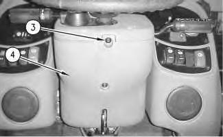 Illustration 1
g00748631
1. Remove torx screws (1) and cover (2) .
Illustration 2
g00748638
2. Remove torx screws (3) and cover (4) .
Illustration 1
g00748631
1. Remove torx screws (1) and cover (2) .
Illustration 2
g00748638
2. Remove torx screws (3) and cover (4) .
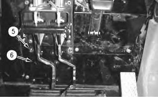
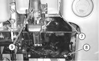
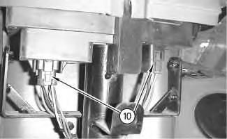 Illustration 3 g00748641
3. Remove torx screws (5) and plate (6) .
Illustration 4 g00748643
4. Remove two nuts (7) and two bolts (8). Position steering column (9) on the floor of the cab.
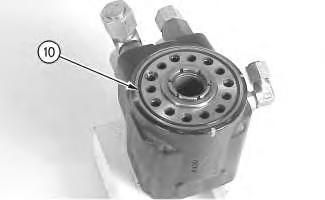
Illustration 5
g00748647
5. Disconnect two connectors (10) .
Illustration 3 g00748641
3. Remove torx screws (5) and plate (6) .
Illustration 4 g00748643
4. Remove two nuts (7) and two bolts (8). Position steering column (9) on the floor of the cab.
Illustration 5
g00748647
5. Disconnect two connectors (10) .
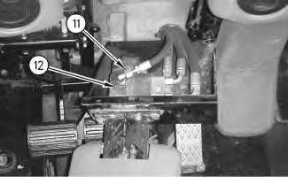
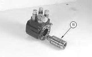
 Illustration 6
g00748668
6. Disconnect five lines (11) from metering valve (12) .
Illustration 7
g00748672
Illustration 6
g00748668
6. Disconnect five lines (11) from metering valve (12) .
Illustration 7
g00748672
Shutdown SIS
Previous Screen
Product: BACKHOE LOADER
Model: 428D BACKHOE LOADER BMT
Configuration: 428D Backhoe Loader BMT01618-03227 (MACHINE) POWERED BY 3054 Engine
Disassembly and Assembly
416D, 420D, 424D, 428D, 430D, 432D, 438D and 442D Backhoe Loaders Machine Systems
Steering Metering Pump - Disassemble
SMCS - 4312-015
Disassembly Procedure
Start By:
A. Remove the steering metering pump. Refer to Disassembly and Assembly, "Steering Metering Pump - Remove" in this manual.
NOTICE
Care must be taken to ensure that fluids are contained during performance of inspection, maintenance, testing, adjusting and repair of the product. Be prepared to collect the fluid with suitable containers before opening any compartment or disassembling any component containing fluids.
Refer to Special Publication, NENG2500, "Caterpillar Tools and Shop Products Guide" for tools and supplies suitable to collect and contain fluids on Caterpillar products.
Dispose of all fluids according to local regulations and mandates.
NOTICE
Keep all parts clean from contaminants.
Contamination of the hydraulic system with foreign material will reduce the service life of the hydraulic system components.
To prevent contaminants from entering the hydraulic system, always plug or cap the lines, fittings, or hoses as they are disconnected. Cover any disassembled components and clean them properly before assembly.
Clean the hydraulic system properly after any major component exchange or especially after a component failure, to remove any contamination.
Note: Put identification marks on all lines, on all hoses, on all wires, and on all tubes for installation purposes.
 Illustration 1
g00768563
Steering metering pump
1. Remove seven bolts (1) .
2. Remove end cap (2) .
Illustration 1
g00768563
Steering metering pump
1. Remove seven bolts (1) .
2. Remove end cap (2) .
3. Remove O-ring seal (3) .
4. Remove housing (4) .
5. Remove O-ring seal (5) .
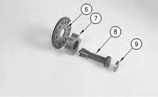
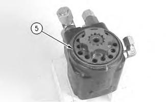
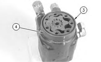 Illustration 2
g00768567
Illustration 3
g00768582
Illustration 4
g00768584
Illustration 2
g00768567
Illustration 3
g00768582
Illustration 4
g00768584
(6) Spacer plate
(7) Star
(8) Drive
(9) Drive spacer
6. Remove drive spacer (9), drive (8), star (7), and spacer plate (6) from the housing.
Illustration 5 g00768590
7. Remove O-ring seal (10) .
Illustration 6
8. Remove spool and sleeve assembly (11) .
Note: Do not bind the spool and sleeve assembly in the housing. Rotate the spool and sleeve assembly slowly in order to remove the assembly from the housing.
Note: During removal, the pin may slide outward from the spool and sleeve assembly which will lock these parts in the housing. If this occurs, center the pin and continue to remove the spool and sleeve assembly.
 g00768594
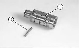

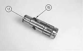 Illustration 7
g00768615
9. Remove pin (12) from the spool and sleeve assembly (11) .
Illustration 8
g00768619
10. Remove spool (13) from the control end of sleeve (14) .
Illustration 7
g00768615
9. Remove pin (12) from the spool and sleeve assembly (11) .
Illustration 8
g00768619
10. Remove spool (13) from the control end of sleeve (14) .
Illustration 9
g00768628
11. Remove centering springs (15) from spool (13) .
Note: The steering metering unit uses six centering springs.
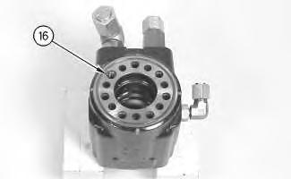
Illustration 10
g00768635
Tapped plug (16) retains the manual steering check valve.
12. Remove tapped plug (16) .
Illustration 11
Manual steering check valve
13. Remove roll pin (18) and ball (17) .
g00768638
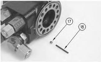
Illustration 12
Anticavitation valves
g00768645
14. Remove two roll pins (20) and two balls (19) from the bolt holes by tipping the housing.
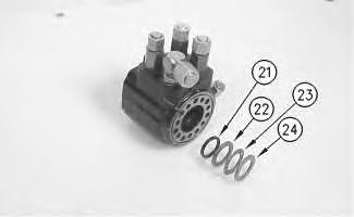

Illustration 13
(21) Seal
(22) Spacer
(23) Needle bearing
(24) Spacer
g00768646
15. Remove spacer (24), needle bearing (23), spacer (22), and seal (21) .
Illustration 14
16. Pry retaining ring (25) from the housing.
Illustration 15
(25) Retaining ring
(26) O-ring seal
(27) Bushing
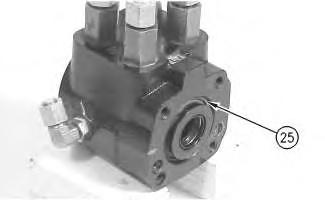
(28) Dust seal
17. Remove dust seal (28), bushing (27), and O-ring seal (26) .
 g00768651
g00768656
g00768651
g00768656
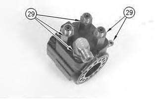
Illustration 16
g00768708
18. Remove five hydraulic fittings (29) in order to complete disassembly of the steering metering unit.
Copyright 1993 - 2019 Caterpillar Inc.
All Rights Reserved. Private Network For SIS Licensees.
Tue Oct 8 21:52:16 UTC+0800 2019
Shutdown SIS
Previous Screen
Product: BACKHOE LOADER
Model: 428D BACKHOE LOADER BMT
Configuration: 428D Backhoe Loader BMT01618-03227 (MACHINE) POWERED BY 3054 Engine
Disassembly and Assembly
416D, 420D, 424D, 428D, 430D, 432D, 438D and 442D Backhoe Loaders Machine Systems
Steering Metering Pump - Assemble
SMCS - 4312-016
Assembly Procedure
Note: Cleanliness is an important factor. Before assembly, all parts should be thoroughly cleaned in cleaning fluid. Allow the parts to air dry. Wiping cloths or rags should not be used to dry parts. Lint may be deposited on the parts which may cause later trouble. Inspect all parts. If any parts are worn or damaged, use new parts for replacement. All disassembly and all assembly procedures must be performed on a clean work surface and in a clean hydraulic area. Keep cleaned parts covered and protected at all times.
Note: O-rings, gaskets, and seals should always be replaced. A used O-ring may not have the same sealing properties as a new O-ring. Use 1U-6396 O-Ring Assembly Compound during the assembly procedure.
Note: Apply a light film of hydraulic oil to all components before assembly.
1. Install five hydraulic fittings (29) .
Illustration 2
(25) Retaining ring
(26) O-ring seal
(27) Bushing
(28) Dust seal
2. Install O-ring seal (26), bushing (27), dust seal (28), and retaining ring (25) .
Illustration 3
(21) Seal
(22) Spacer
(23) Needle bearing
(24) Spacer
3. Install seal (21), spacer (22), needle bearing (23), and spacer (24) .
g00768656 g007686464. Install centering springs (15) into spool (13) .
Note: The steering metering pump uses six centering springs.
Note: The centering spring notches must face away from the splined end of the spool.
5. Install spool (13) into sleeve (14) .
Illustration 4 g00768628 Illustration 5 g00768619g00768615
6. Insert pin (12) through spool and sleeve assembly (11). The pin should be flush with both sides of the sleeve.
g00768594
7. Insert spool and sleeve assembly (11) into the housing. Insert the spool and sleeve assembly until the spool and sleeve assembly are flush with the end of the housing.
Note: Do not insert the spool and sleeve assembly beyond this point. The pin may become stuck in the discharge groove.
8. Check for free rotation of the spool and sleeve assembly by turning the assembly with fingertip force at the splined end.
Illustration 6 Illustration 7Illustration 8 g00768970
(8) Drive
(12) Pin
(30) Port face
9. Rotate the spool and sleeve assembly until the pin is parallel with port face (30) .

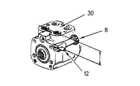
10. Install drive (8).
Illustration 9 g00769135
(6) Spacer plate
(10) O-ring seal
(17) Ball
(18) Roll pin
(19) Ball
(20) Roll pin
11. Install two balls (19) and two roll pins (20) .
12. Install ball (17) and roll pin (18) .
13. Install the tapped plug in order to retain the check valve for manual steering.
14. Install O-ring seal (10) and spacer plate (6) .
Note: Align bolt holes in the spacer plate with the tapped holes in the housing.
Illustration 10
(4) Housing
(5) O-ring seal
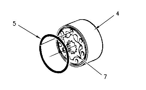
(7) Star
15. Install O-ring seal (5), and star (7) in gerotor housing (4) .
g00768980
Suggest:
If the above button click is invalid.
Please download this document first, and then click the above link to download the complete manual.
Thank you so much for reading

Illustration 11 g00769023
(4) Housing
(7) Star
(8) Drive
(12) Pin
16. Make a mark (B) on drive (8) parallel to pin (12) .
17. Align star valleys (A) with marked drive (B), pin (C), and port face (D) .
Note: Proper alignment of the star is critical in order to ensure proper operation of the steering metering pump. The star valleys must align with the pin. Align bolt holes without disengaging the gerotor from the drive.
