Previous Screen
Product: EXCAVATOR
Model: 390F EXCAVATOR FEH
Configuration: 390F L Excavator FEH00001-UP (MACHINE) POWERED BY C18 Engine
Disassembly and Assembly 390F Excavator Machine Systems
Travel Motor - Disassemble
SMCS - 4351-015
Disassembly Procedure Table 1
Required Tools
Start By:
a. Remove the travel motor.
NOTICE
Care must be taken to ensure that fluids are contained during performance of inspection, maintenance, testing, adjusting, and repair of the product. Be prepared to collect the fluid with suitable containers before opening any compartment or disassembling any component containing fluids.
Refer to Special Publication, NENG2500, "Dealer Service Tool Catalog" for tools and supplies suitable to collect and contain fluids on Cat products.
Dispose of all fluids according to local regulations and mandates.
Note: Cleanliness is an important factor. Before you begin the disassembly procedure, the exterior of the components should be thoroughly cleaned. This will help to prevent dirt from entering the internal mechanism. Precision components can be damaged by contaminants or by dirt. Perform disassembly procedures on a clean work surface. Keep components covered and protected at all times.
1. Place an alignment mark across all housings of the travel motor for assembly purposes.

Personal injury can result from parts and/or covers under spring pressure.
Spring force will be released when covers are removed.
Be prepared to hold spring loaded covers as the bolts are loosened.
2. Remove two socket head bolts (2) from head (1) that are 180 degrees from each other. Replace these two bolts with Tooling (G). Tooling (G) will retain the brake cover when the remaining socket head bolts (2) are removed.
3. Carefully remove the remaining socket head bolts (2) that retain head (1) in position. Remove socket head bolts (2) evenly, in a crisscross pattern.
4. Remove Tooling (G) from head (1).
Illustration 1 g012828325. Install Tooling (A) and a suitable lifting device to head (1).
6. Remove head (1) from the travel motor. The weight of head (1) is approximately 68 kg (150 lb).
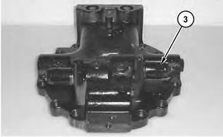
7. Remove relief valve (3).
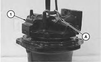 Illustration 2 g01283040
Illustration 3 g01283045
Illustration 4 g01283049
Illustration 2 g01283040
Illustration 3 g01283045
Illustration 4 g01283049
Personal injury can result from being struck by parts propelled by a released spring force.
Make sure to wear all necessary protective equipment.
Follow the recommended procedure and use all recommended tooling to release the spring force.
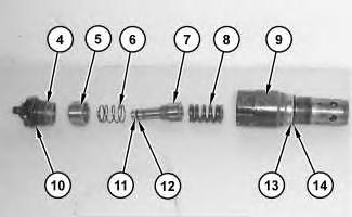
8. Remove cap (4) from body (9). Remove piston (5), spring (6), spool (7), and spring (8) from body (9).
9. Remove O-ring seals (10), (12), and (14). Remove backup rings (11) and (13).
10. Remove the other relief valve from the other side of the head.
11. Repeat Steps 8 and 9 for the disassembly of the other relief valve.
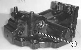
12. Remove plug (15).
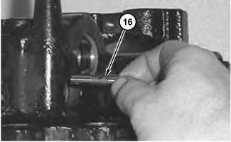
Illustration 5 g01283057 Illustration 6 g0128306013. Remove spool (16).
Personal injury can result from being struck by parts propelled by a released spring force.
Make sure to wear all necessary protective equipment.
Follow the recommended procedure and use all recommended tooling to release the spring force.
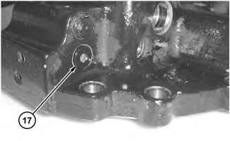
14. Remove plug (17).
15. Remove spool (21) from the head. Remove O-ring seal (22) from plug (17).
16. Remove plug (18) from the other side of the head. Remove spring (20). Remove O-ring seal (19) from plug (18).
 Illustration 7 g01283070
Illustration 8 g01283075
Illustration 7 g01283070
Illustration 8 g01283075
Illustration 9
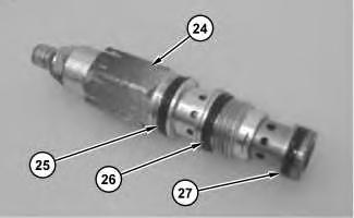
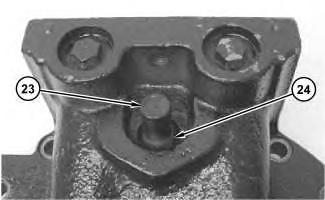
17. Remove cap (23) and pressure reducing valve (24).
Illustration 10
18. Remove O-ring seals (25), (26), and (27) from pressure reducing valve (24).

Illustration 11
19. Use Tooling (B) in order to remove bearing (28) from the head.
 g01283083
g01283088
g01283096
g01283083
g01283088
g01283096
Illustration 12
g01283101
20. Remove port plate (29) from the travel motor.
Note: Note the location of springs (30) before removal.
21. Remove springs (30) from the travel motor.
22. Remove O-ring seals (31).
Illustration 13
g01283110
23. Place alignment marks on piston (32) and the housing. The dowel hole in piston (32) must be reinstalled to the original location.
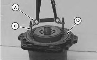
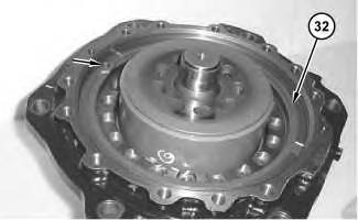

Illustration 14
g01283120
24. Install Tooling (C) to the threaded holes in piston (32). Install Tooling (A) and a suitable lifting device on Tooling (C), as shown. Remove piston (32) from the travel motor.
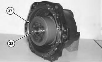

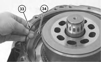
Illustration 15
g01283129
25. Remove O-ring seals (33) and (34) from the travel motor.
Illustration 16
g01283133
26. Remove separator plates (35) and friction plates (36) from the travel motor.
Illustration 17
g01283138
Illustration 18
g01283139
Note: Barrel assembly (37), piston assemblies (39), and retainer (40) must remain intact during removal.
27. Position the travel motor sideways. Carefully remove barrel assembly (37) from shaft (38).
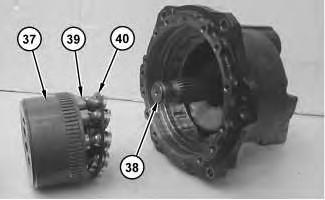
Illustration 19
g01283155
28. Place identification marks on piston assemblies (39), retainer (40), and barrel assembly (37). These components must be reinstalled in the original location.
29. Remove retainer (40) and piston assemblies (39) from barrel assembly (37).
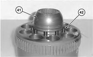
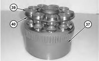
Illustration 20 g01283175
Illustration 21 g01283193
30. Remove guide (41).
31. Remove springs (42).
Illustration 22 g01283187
32. Turn swashplate (43) counterclockwise in order to provide clearance for the removal of swashplate (43).

33. Remove swashplate (43) from the travel motor housing.

Illustration 23
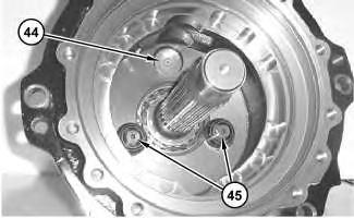
34. Remove piston (44) and pivots (45).
Illustration 24
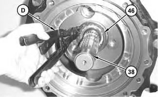
35. Use Tooling (D) in order to remove retaining ring (46) from shaft (38).
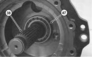
Illustration 25
36. Use a soft hammer in order to drive shaft (38) and bearing (47) from the motor housing.
 g01283195
g01283206
g01283209
g01283195
g01283206
g01283209
Illustration 26
37. Use Tooling (E) in order to remove retaining ring (48) from bearing (47).
Illustration 27
38. Use a suitable press in order to remove bearing (47) from shaft (38).
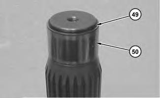
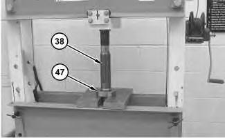
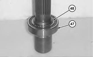
Illustration 28
39. Remove retaining ring (49) and bearing race (50).
g01283212 g01283232 g01283244
Previous Screen
Product: EXCAVATOR
Model: 390F EXCAVATOR FEH
Configuration: 390F L Excavator FEH00001-UP (MACHINE) POWERED BY C18 Engine
Disassembly and Assembly
390F Excavator Machine Systems Media
Travel Motor - Assemble
SMCS - 4351-016
Assembly Procedure
Note: Cleanliness is an important factor. Before assembly, all parts should be thoroughly cleaned in cleaning fluid. Allow the parts to air dry. Wiping cloths or rags should not be used to dry parts. Lint may be deposited on the parts which may cause later trouble. Inspect all parts. If any parts are worn or damaged, use new parts for replacement.
Note: Apply a light film of 10W oil to all components before assembly.
1. Use Tooling (F) in order to install lip seal (51) in the travel motor housing.
2. Install bearing (50) and retaining ring (49).
3. Raise the temperature of bearing (47). Install bearing (47) onto shaft (38).
 Illustration 1
g01283253
Illustration 2
g01283244
Illustration 3
g01283329
Illustration 4
g01283212
4. Use Tooling (E) in order to install retaining ring (48) onto bearing (47).
Illustration 5
g01283209
5. Install shaft (38) and bearing (47) into the motor housing.
Illustration 6
g01283206
6. Use Tooling (D) in order to install retaining ring (46) onto shaft (38).
Illustration 7
g01283195
7. Install piston (44) and pivots (45).
Illustration 8
g01283187
8. Install swashplate (43).
Illustration 9
g01283193
Illustration 1
g01283253
Illustration 2
g01283244
Illustration 3
g01283329
Illustration 4
g01283212
4. Use Tooling (E) in order to install retaining ring (48) onto bearing (47).
Illustration 5
g01283209
5. Install shaft (38) and bearing (47) into the motor housing.
Illustration 6
g01283206
6. Use Tooling (D) in order to install retaining ring (46) onto shaft (38).
Illustration 7
g01283195
7. Install piston (44) and pivots (45).
Illustration 8
g01283187
8. Install swashplate (43).
Illustration 9
g01283193
Illustration 10
Improper assembly of parts that are spring loaded can cause bodily injury.
To prevent possible injury, follow the established assembly procedure and wear protective equipment.
9. Install springs (42).
10. Install guide (41).
Illustration 11
11. Install retainer (40) and piston assemblies (39) into barrel assembly (37). These components must be reinstalled in the original location.
g01283175
g01283155
12.
Note: Barrel assembly (37), piston assemblies (39), and retainer (40) must remain intact during installation onto shaft (38).
Illustration 12 g01283139
Position the travel motor sideways.
Illustration 13
g01283138
13. Carefully install barrel assembly (37) onto shaft (38).
Illustration 14
g01283133
14. Install separator plates (35) and friction plates (36) into the travel motor.
Illustration 15
15. Install O-ring seals (33) and (34) into the travel motor.
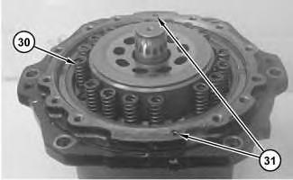
Illustration 16
Note: Piston (32) must be reinstalled in the original location.
16. Install piston (32).
17
g01283129
g01283110
Illustration
g01283350
Improper assembly of parts that are spring loaded can cause bodily injury.
To prevent possible injury, follow the established assembly procedure and wear protective equipment.
Note: Note the location of springs (30) for installation.
17. Install springs (30) and O-ring seals (31) to the travel motor.
18. Lower the temperature of bearing (28). Install bearing (28) in the head.
19. Install O-ring seals (25), (26), and (27) on pressure reducing valve (24).
Illustration 18
g01283096
Illustration 19
g01283088
g01283083
20. Install pressure reducing valve (24). Tighten pressure reducing valve (24) to a torque of 44 ± 4 N·m (33 ± 3 lb ft).
21. Install cap (23).
g01283075
22. Install O-ring seal (22) onto plug (17). Install spool (21) and plug (17) to the head.
23. Install O-ring seal (19) onto plug (18). Install spring (20) and plug (18) to the head.
24. Tighten plugs (17) and (18) to a torque of 74 ± 7 N·m (55 ± 5 lb ft).
Illustration 20
Illustration 21
Illustration 22
25. Install spool (16).
Illustration 23
26. Install plug (15).
Illustration 24
Improper assembly of parts that are spring loaded can cause bodily injury.
To prevent possible injury, follow the established assembly procedure and wear protective equipment.
27. Install O-ring seals (10), (12), and (14) and backup rings (11) and (13).
28. Install piston (5), spring (6), spool (7), and spring (8) in body (9). Install cap (4) in body (9).
29. Repeat Steps 27 and 28 for the assembly of the other relief valve.
g01283060
g01283057
g01283049
Suggest:
If the above button click is invalid.
Please download this document first, and then click the above link to download the complete manual.
Thank you so much for reading

Illustration 25
g01283045
30. Install relief valves (3). Tighten relief valves (3) to a torque of 177 ± 18 N·m (131 ± 13 lb ft).
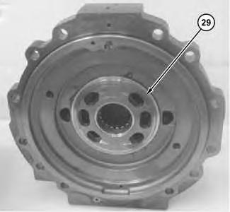
Illustration 26
g01283396
31. Use light grease to install port plate (29) on the head.