Shutdown SIS
Previous Screen
Product: EXCAVATOR
Model: 385B EXCAVATOR BLY
Configuration: 385B & 385B L Excavators BLY00001-UP (MACHINE) POWERED BY 3456 Engine
Disassembly and Assembly
385B and 5090B Excavators Excavator Systems
Final Drive - Disassemble
SMCS - 4050-015
Disassembly Procedure Table 1
Required Tools
Start By:
a. Remove the final drive. Refer to Disassembly and Assembly, "Final Drive - Remove".
1. Thoroughly clean the outside of the final drive prior to disassembly.
2. Fasten the final drive to Tooling (A). Put an alignment mark across the sections of the final drive for assembly purposes. All parts must be reinstalled in the original locations. The weight of the final drive is approximately 1020 kg (2250 lb).
3. Remove socket head bolts (1) from the final drive cover.
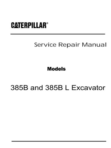
4. Fasten Tooling (B) and a suitable lifting device to cover (2).
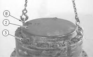
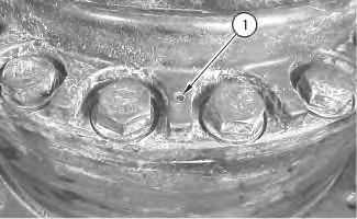
 Illustration 1
g00865168
Illustration 2
g00865172
Illustration 3
g00865173
Illustration 1
g00865168
Illustration 2
g00865172
Illustration 3
g00865173
5. Remove bolts (3). Use a soft faced hammer to break the seal between the cover and the ring gear. Remove cover (2). The weight of the cover is approximately 95 kg (210 lb).
6. Remove spacer (4) and the shims from the cover.
7. Remove socket head bolts (5) and ring gear (6) from the cover.
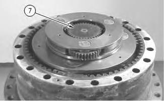
8. Remove sun gear (7).
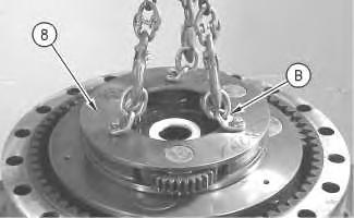
Illustration 4 g00865183 Illustration 5 g00865487 Illustration 6 g008655019. Use a hoist and Tooling (B) to remove carrier assembly (8). The weight of the carrier assembly is approximately 43 kg (95 lb).
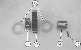
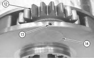
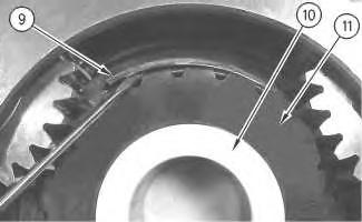 Illustration 7
g00865534
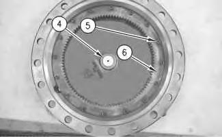
10. Remove retaining ring (9), spacer (10), and sun gear (11).
Illustration 8
g00865551
11. Drive spring pin (13) into shaft (14). Remove shaft (14) and gear assembly (12).
Illustration 9
g00865614
Illustration 7
g00865534
10. Remove retaining ring (9), spacer (10), and sun gear (11).
Illustration 8
g00865551
11. Drive spring pin (13) into shaft (14). Remove shaft (14) and gear assembly (12).
Illustration 9
g00865614
12. Remove washers (15) and bearing (16) from gear (17). Remove spring pin (13) from shaft (14).

13. Repeat Steps 11 and 12 for the remaining gear assemblies.
Illustration 10
g00865671
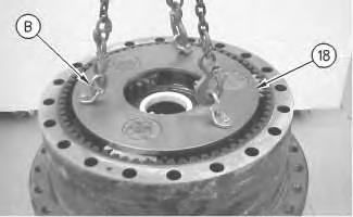
14. Use a hoist and Tooling (B) to remove carrier assembly (18). The weight of the carrier assembly is approximately 95 kg (210 lb).
Illustration 11
g00865717
15. Remove retaining ring (19), spacer (20), and gear assembly (21).
Illustration 12
g00865736
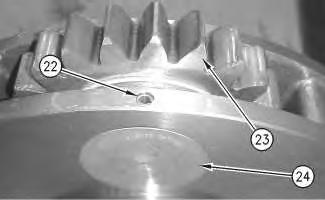
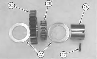
16. Drive spring pin (22) into planetary shaft (24). Remove planetary shaft (24) and gear assembly (23).
Illustration 13
g00865753
17. Remove thrust washers (27) and bearing (26) from planetary gear (25). Remove spring pin (22) from shaft (24).
18. Repeat Steps 16 and 17 for the remaining gear assemblies.
Illustration 14
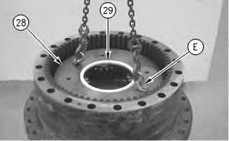
19. Use a hoist and Tooling (B) to remove carrier assembly (28). The weight of the carrier assembly is approximately 132 kg (290 lb). Remove spacer (29).
g0086586220. Drive spring pin (31) into shaft (32). Remove planetary shaft (32) and gear assembly (30).
21. Remove thrust washers (33) and (37), and bearings (34) and (36) from planetary gear (35). Remove spring pin (31) from shaft (32).
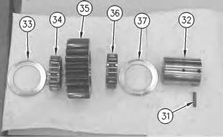
22. Repeat Steps 20 and 21 for the remaining gear assemblies.
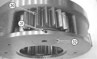 Illustration 15
g00865872
Illustration 16
g00865884
Illustration 17
g00865931
Illustration 15
g00865872
Illustration 16
g00865884
Illustration 17
g00865931
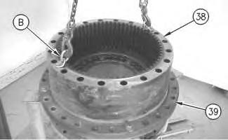
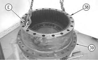
23. Use a hoist and Tooling (B) to remove ring gear (38) from housing (39). The weight of the ring gear is approximately 155 kg (340 lb).
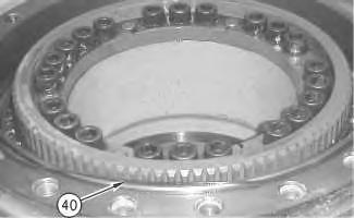
24. Remove O-ring seal (40) from the main housing.
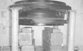
25. Place wood blocks under the final drive in order to support the motor housing.
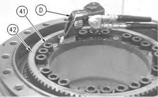
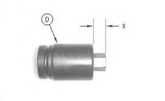
Illustration 18 g00865939 Illustration 19 g00865955 Illustration 20 g0086604726. Use Tooling (D) to remove bolts (41) from gear (42).
Note: A part of Tooling (D) must be modified. Cut Length (X) on a 9U-7418 Hex Bit Socket to a length of 14 mm (0.55 inch).
27. Install Tooling (E) in the gear, as shown. Tighten Tooling (E) evenly in order to loosen the gear. Remove the gear from the motor housing.
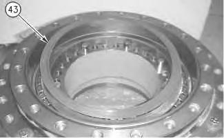
 Illustration 21
g00865969
Illustration 22
g00866066
Illustration 23
g00866072
Illustration 21
g00865969
Illustration 22
g00866066
Illustration 23
g00866072
28. Remove shims (43) from the motor housing.
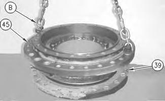
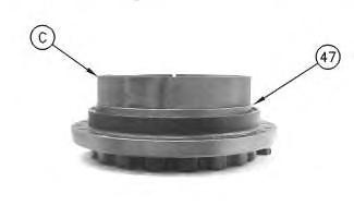
29. Remove bolts (44). Use Tooling (C) and a hoist to separate main housing (45) from motor housing (39). The motor housing will rest on the wood blocks. The weight of the main housing is approximately 250 kg (550 lb).
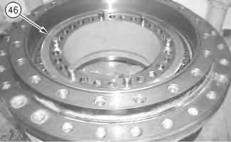
30. Remove bearing (46) from the main housing.

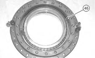
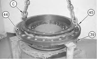 Illustration 24 g00866085
Illustration 25 g00866095
Illustration 26 g00866100
Illustration 24 g00866085
Illustration 25 g00866095
Illustration 26 g00866100
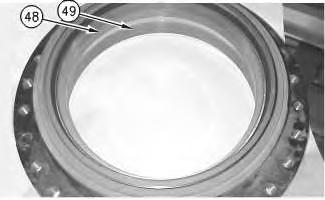
31. Remove Duo-Cone seal (47), and bearing cups (48) and (49) from the main housing.

Illustration 27
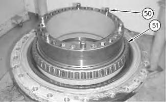
32. Remove pins (50), if necessary.
33. Remove bearing (51).
34. Remove Duo-Cone seal (52) from the motor housing.
Copyright 1993 - 2020 Caterpillar Inc. All Rights Reserved. Private Network For SIS Licensees.
g00866156Shutdown SIS
Previous Screen
Product: EXCAVATOR
Model: 385B EXCAVATOR BLY
Configuration: 385B & 385B L Excavators BLY00001-UP (MACHINE) POWERED BY 3456 Engine
Disassembly and Assembly
385B and 5090B Excavators Excavator Systems
Final Drive - Assemble
SMCS - 4050-016
Assembly Procedure
Table 1
Required Tools
1. Make sure that all parts of the final drive are thoroughly clean and free of dirt and debris prior to assembly.
Note: Check the condition of all the O-ring seals that are used in the final drive. If any of the seals are worn or damaged, use new parts for replacement.
2. Reassemble the final drive on wood blocks and Tooling (A).
3. Apply 5P-3931 Anti-Seize Compound to the surfaces that contact the bearing cones. Install the bearing cone with a press. Raise the temperature of bearing (51) and install the bearing.
4. Apply 5P-3931 Anti-Seize Compound to the surfaces that contact pins (50). Install the pins.
5. Apply 5P-3931 Anti-Seize Compound to the surfaces that contact the two bearing cups. Install bearing cups (48) and (49).
6. Use Tooling (B) and a suitable lifting device to install main housing (45) on motor housing (39). The weight of the main housing is approximately 250 kg (550 lb).
7. Install bearing (46) and the bearing cone.
8. Use the following procedure to determine the bearing preload and the correct number of shims.
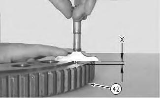 Illustration 3
g00875677
Illustration 4
g00875859
Illustration 3
g00875677
Illustration 4
g00875859
a. Use a depth micrometer in order to measure the step length of the coupling gear (42). Take measurements at several different locations around the gear. Compute the average of the measured dimensions and record the number. Call this Dimension (X).
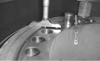
b. Use Tooling (F) to apply a load of 10700 kPa (1550 psi) in order to seat the bearings. A pressure of 10700 kPa (1550 psi) on the 3S-6224 Electric Hydraulic Pump Gp will result in a pressure of 10000 kg (22050 lb) on the bearings. Rotate the housing in order to seat the bearing. Reduce the load on the 3S-6224 Electric Hydraulic Pump Gp to 4825 kPa (700 psi).
c. Rotate Tooling (F) by 90° and repeat Step 8.b.
d. Maintain the load on the bearings. Use a depth micrometer and measure the distance between the top face of motor housing and the bearing cone. Take this measurement in several locations around the bearing. Compute the average of the measured dimensions and record the number. Call this Dimension (Y).
e. Determine the correct thickness of the shim pack that will be installed between the bearing cone and the coupling gear. The shim pack thickness is equal to Dimension (Y) minus Dimension (X). Tolerance for the shim pack is 0.1 mm (0.003 inch).
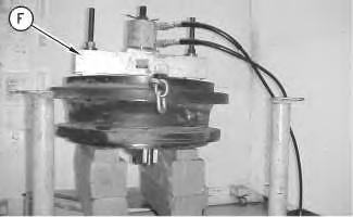 Illustration 5 g00603328
Illustration 6
g00876170
Illustration 7
g00876133
Illustration 5 g00603328
Illustration 6
g00876170
Illustration 7
g00876133
Note: If two shims are required, install the thinner shim next to the coupling gear when the coupling gear is installed.
9. Use Tooling (B) and a suitable lifting device to remove the main housing from the motor housing. The weight of the main housing is approximately 250 kg (550 lb).
Note: Refer to Disassembly and Assembly, "Duo-Cone Conventional Seals - Install".
Note: The rubber seals and all surfaces that contact the seals must be clean and dry. After installation of the seals, apply clean SAE 30 oil on the contact surfaces of the metal seals.
g00876775
10. Use Tooling (C) to install Duo-Cone seal (47) in the main housing.
g00876788
11. Use Tooling (C) to install Duo-Cone seal (52) in the motor housing.
Note: Make sure that the Duo-Cone seals are not scratched or damaged during the assembly of the main housing or during the assembly of the motor housing. After installation of the main housing on the motor housing, there will be a small gap between the components. The gap is caused by the Duo-Cone seals. The gap will be eliminated during installation of the gear.
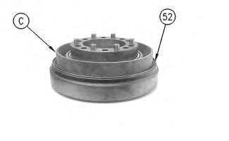 Illustration 8
Illustration 9
Illustration 8
Illustration 9
12. Fasten Tooling (B) and a hoist to main housing (45). Place the main housing in position on motor housing (39). Make sure that the Duo-Cone seals are not scratched or damaged during installation. The weight of the main housing is approximately 250 kg (550 lb).
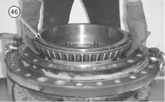 Illustration 10
g00875677
Illustration 11 g00876801
13. Install bearing (46) and the bearing cone.
Illustration 12
g00866072
Illustration 10
g00875677
Illustration 11 g00876801
13. Install bearing (46) and the bearing cone.
Illustration 12
g00866072
Illustration 13
14. Place shims (43) in the correct position on the motor housing. If two shims were required, put the thinner shim in contact with coupling gear (42). Make sure that all of the holes in the components are in alignment with each other. Put coupling gear (42) in the original position on the motor housing.
15. Apply 9S-3263 Thread Lock Compound on the threads of bolts (41). Install the bolts to secure coupling gear (42) in place. Tighten the bolts evenly and tighten the bolts in diagonally opposite pairs. Tighten bolts to a torque of 900 ± 100 N·m (665 ± 75 lb ft).
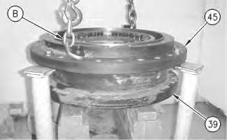
Illustration 14
16. Install O-ring seal (40) in the main housing.
g00866047 g00865939Illustration 15
g00876919
17. Use Tooling (B) and a hoist to position housings (39) and (45) on Tooling (A). Remove the wood blocks. The weight of both housings is approximately 430 kg (950 lb).
Illustration 16
g00876937
18. Thoroughly clean the mating surface of main housing (39) that contacts ring gear (38). Apply a bead of 1U-8846 Gasket Sealant on the mating surface of ring gear (38). Use Tooling (E) and a suitable lifting device. Place the ring gear in position on the main housing. Make sure that the alignment mark on the main housing and the ring gear line up with each other. It may be necessary to use a soft faced hammer to seat the ring gear on the main housing.
19. Assemble carrier assembly (28), as follows:
Illustration 17
g00865884g00865872
a. Apply clean SAE 30 oil on bearings (34) and (36). Install two bearings (34) and (36) in planetary gear (35).
b. Install thrust washers (33) and (37) on each side of the planetary gear.
c. Install the planetary gear and thrust washers in carrier assembly (28).
d. Install planetary shaft (32) in carrier assembly (28) and through planetary gear assembly (30). Make sure that the spring pin hole in the planetary shaft is in alignment with the spring pin hole in the carrier.
g00513451
e. Install spring pin (31) in the carrier and into the planetary shaft. Make sure that the spring pin hole in the planetary shaft is in alignment with the spring pin hole in the carrier.
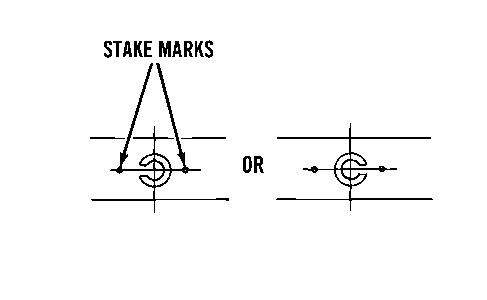
f. Orient the split in spring pin (31) horizontally to the carrier. Align the split in the spring pin to the left or to the right. Make a stake mark on each side of the spring pin hole in the carrier. This will prevent the spring pin from falling out of the spring pin
Illustration 18 Illustration 19hole. Each stake mark should be approximately 1.5 mm (0.06 inch) to 3.00 mm (0.118 inch) from the outside diameter of the spring pin hole.
g. Repeat Steps 19.a through 19.f in order to install the other three planetary gears in carrier assembly (28).
20. Fasten Tooling (E) and a hoist to carrier assembly (28). Put the carrier assembly in position in the ring gear. It may be necessary to move the carrier assembly back and forth during installation in order to ensure that all gears engage properly.
21. Install spacer (29).
22. Assemble carrier assembly (21), as follows:
a. Apply clean SAE 30 oil on bearing (26). Install bearing (26) in planetary gear (25).
b. Install thrust washers (27) on each side of the planetary gear.
c. Install the thrust washers and the planetary gear in carrier assembly (28).
Illustration 20 g00865862 Illustration 21 g00865753g00865736
d. Install planetary shaft (24) in carrier assembly (28) and through the planetary gear assembly. Make sure that the spring pin hole in the planetary shaft is in alignment with the spring pin hole in the carrier.
g00513451
e. Orient the split in the spring pin (22) horizontally to the carrier. Align the split in the spring pin to the left or to the right. Make a stake mark on each side of the spring pin hole in the carrier. This will prevent the spring pin from falling out of the spring pin hole. Each stake mark should be approximately 1.5 mm (0.06 inch) to 3.00 mm (0.118 inch) from the outside diameter of the spring pin hole.
f. Repeat Steps 22.a through 22.e in order to install the other two planetary gears in carrier assembly (28).
Illustration 22
Illustration 23
23. Install gear assembly (21), spacer (20), and retaining ring (19).
24. Use a hoist and Tooling (B) to install carrier assembly (18). The weight of the carrier assembly is approximately 95 kg (210 lb).
25. Apply clean SAE 30 oil on bearing (16). Install washers (15) and bearing (16) in gear (17).
Illustration 24
g00865717
Illustration 25
g00865671
Illustration 26
g00865614
g00865551
26. Install gear assembly (12), shaft (14), and drive spring pin (13) into shaft (14).
27. Repeat Steps 25 and 26 for the remaining gear assemblies.
g00865534
28. Install sun gear (11), spacer (10), and retaining ring (9).
g00865501
29. Use a hoist and Tooling (B) to install carrier assembly (8). The weight of the carrier assembly is approximately 43 kg (95 lb).
Illustration 27
Illustration 28
Illustration 29
Suggest:
If the above button click is invalid.
Please download this document first, and then click the above link to download the complete manual.
Thank you so much for reading

Illustration 30 g00865487
30. Install sun gear (7).
Illustration 31
g00865183
31. Install the shims and spacer (4) in the cover.
32. Install ring gear (6) and socket head bolts (5) in the cover.
Illustration 32
g00865173
33. Use Tooling (B) and a suitable lifting device to position cover (2). Install bolts (3). The weight of the cover is approximately 95 kg (210 lb).