Shutdown SIS
Previous Screen
Product: MOBILE HYD POWER UNIT
Model: 336E HVG MOBILE HYD POWER UNIT RBS
Configuration: 336E L HVG UHD Mobile Hydraulic Power Unit RBS00001-UP (MACHINE) POWERED BY C9.3 Engine
Disassembly and Assembly
C9.3
Engines for Caterpillar Built Machines
Flywheel - Install
SMCS - 1156-012
Installation Procedure Table 1
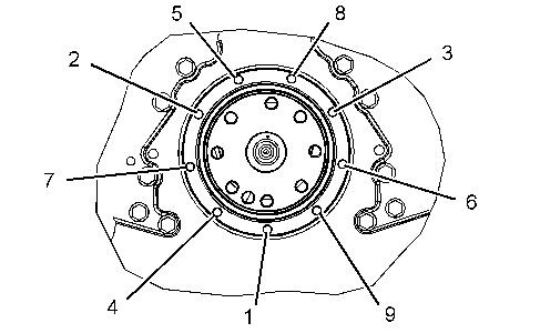
1. Raise the temperature of the flywheel ring gear. Do not use a torch to heat the flywheel ring gear. Install the flywheel ring gear on the flywheel. Position the flywheel ring gear with the part number toward the crankshaft. Allow the flywheel ring gear to cool. Use a soft hammer in order to seat the flywheel ring gear against the shoulder of the flywheel.
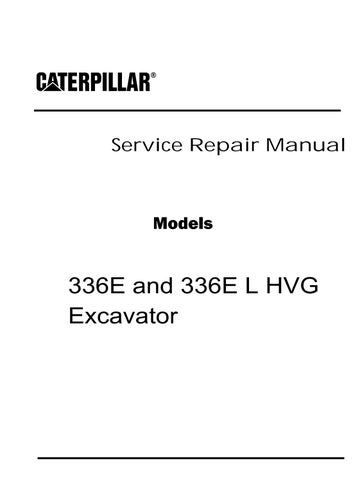
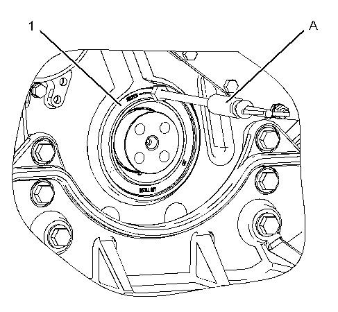
Illustration 1
g01138041
2. Attach Tooling (B) and a suitable lifting device to flywheel (2). The weight of flywheel (2) is approximately 40 kg (85 lb).
3. Position flywheel (2) on Tooling (A).
4. Apply Tooling (D) to the threads of bolts (1).
Note: Tooling (C) should be removed at this time, if Tooling (C) was used in the removal procedure for the flywheel.
5. Install bolts (1). Remove Tooling (A) and install remaining bolt (1). Tighten the bolts evenly to a torque of 300 ± 40 N·m (221 ± 30 lb ft).
6. Check the flywheel runout. Refer to Testing and Adjusting, "Flywheel - Inspect".
Copyright 1993 - 2020 Caterpillar Inc.
Shutdown SIS
Previous Screen
Product: MOBILE HYD POWER UNIT
Model: 336E HVG MOBILE HYD POWER UNIT RBS
Configuration: 336E L HVG UHD Mobile Hydraulic Power Unit RBS00001-UP (MACHINE) POWERED BY C9.3 Engine
Disassembly and Assembly
C9.3
Engines for Caterpillar Built Machines
Crankshaft Rear Seal - Remove
SMCS - 1161-011
Removal Procedure
Start By:
A. Remove the flywheel. Refer to Disassembly and Assembly, "Flywheel - Remove".
NOTICE
Care must be taken to ensure that fluids are contained during performance of inspection, maintenance, testing, adjusting, and repair of the product. Be prepared to collect the fluid with suitable containers before opening any compartment or disassembling any component containing fluids.
Refer to Special Publication, NENG2500, "Dealer Service Tool Catalog" for tools and supplies suitable to collect and contain fluids on Cat products.
Dispose of all fluids according to local regulations and mandates.
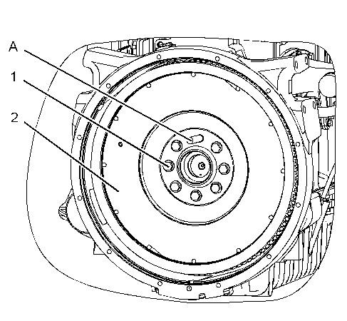
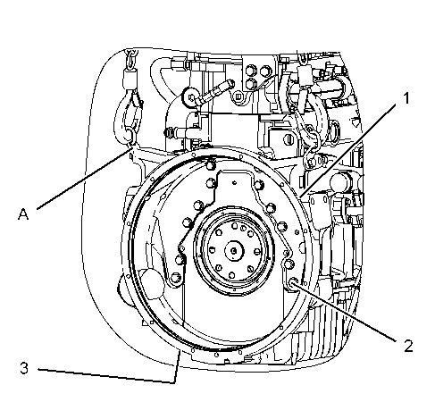
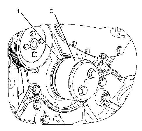
Illustration 1
1. Remove bolts (2) .
2. Remove crankshaft rear seal (1) from the crankshaft.
g01140085
Note: Refer to Reuse and Salvage Guidelines, SEBF8039, "Crankshaft Visual Inspection and Magnetic Particle Inspection" for the correct inspection procedure of the crankshaft seal surface.
Note: Refer to Reuse and Salvage Guidelines, SEBF9217, "Specifications for Crankshafts C7, C9, C-9, C10, C11, C12, C-12, C13, C-13, C15, C-15, C18, C-18, C27, C30, and C32 Engines" or the correct specifications of the crankshaft.
Copyright 1993 - 2020 Caterpillar Inc.
All Rights Reserved. Private Network For SIS Licensees.
Shutdown SIS
Previous Screen
Product: MOBILE HYD POWER UNIT
Model: 336E HVG MOBILE HYD POWER UNIT RBS
Configuration: 336E L HVG UHD Mobile Hydraulic Power Unit RBS00001-UP (MACHINE) POWERED BY C9.3 Engine
Disassembly and Assembly
C9.3
Engines for Caterpillar Built Machines
Crankshaft Rear Seal - Install
SMCS - 1161-012
Installation Procedure
NOTICE
Keep all parts clean from contaminants.
Contaminants may cause rapid wear and shortened component life.
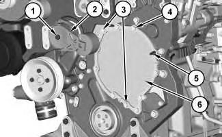
Illustration 2
Numerical tightening sequence for bolts (2).
Note: If required, install a crankshaft wear sleeve at engine overhaul. For more information please refer to the following Reuse and Salvage Guidelines. Refer to Reuse and Salvage Guidelines, SEBF9217, "Specifications for Crankshafts C7, C9, C-9, C10, C11, C12, C-12,
Illustration 1 g01140085
g03698745
C13, C-13, C15, C-15, C18, C-18, C27, C30, and C32 Engines" or the correct specifications of the crankshaft. Refer to Reuse and Salvage Guidelines, SEBF8039, "Crankshaft Visual Inspection and Magnetic Particle Inspection" for the correct inspection procedure of the crankshaft seal surface.
1. If a crankshaft wear sleeve is necessary, refer to Step 1.a through Step 1.d to install the crankshaft wear sleeve. If a crankshaft wear sleeve is not necessary, refer to Step 2.
a. Clean and polish the crankshaft of imperfections.
b. Use Tooling (A) to clean the outside diameter of the crankshaft and the inside diameter of the crankshaft wear sleeve.
c. Apply Tooling (B) to the outside diameter of the crankshaft and the inside diameter of the crankshaft wear sleeve.
d. Use Tooling (C) to install the crankshaft wear sleeve.
Note: Leave the shipping sleeve in place to install the crankshaft rear seal. The crankshaft rear seal must be installed dry.
Note: If the seal group, O-ring seal, and the shipping sleeve are separated, these components should not be used.
2. Lubricate the O-ring seal with clean engine oil that is on the back of the crankshaft rear seal (1).
3. Position crankshaft rear seal (1) and the shipping sleeve over the crankshaft. Push crankshaft rear seal (1) in place. This will dislodge the shipping sleeve.
Note: Do not remove the shipping sleeve until bolts (2) are installed.
4. Install new bolts (2) hand tight. Then, tighten bolts (2) in numerical sequence, shown in Illustration 2. Tighten bolts (2) to a torque of 12 ± 3 N·m (106 ± 27 lb in).
End By:
a. Install the flywheel. Refer to Disassembly and Assembly, "Flywheel - Install".
Shutdown SIS
Previous Screen
Product: MOBILE HYD POWER UNIT
Model: 336E HVG MOBILE HYD POWER UNIT RBS
Configuration: 336E L HVG UHD Mobile Hydraulic Power Unit RBS00001-UP (MACHINE) POWERED BY C9.3 Engine
Disassembly and Assembly
C9.3
Engines for Caterpillar Built Machines
Flywheel Housing - Remove and Install
SMCS - 1157-010
Removal Procedure Table 1
Required Tools
Tool Part Number Part Description Qty
A 138-7575 Link Bracket 2
Start By:
a. Remove the flywheel.
Illustration 1
g01138072
1. Fasten Tooling (A) and a suitable lifting device to flywheel housing (1). The weight of flywheel housing (1) is approximately 25 kg (55 lb).
2. Remove bolts (2).
3. Remove bolts (3) (not shown) that fasten the engine oil pan to flywheel housing (1). Remove flywheel housing (1).
Installation Procedure
Table 2
Required Tools
Tool Part Number
A 138-7575 Link Bracket
B - LoctiteHigh Flex Form-In-Place Gasket
1. Apply Tooling (B) to the entire mounting surface of the flywheel housing prior to installation.
Illustration 2
g01138072
2. Fasten Tooling (A) and a suitable lifting device to flywheel housing (1). The weight of flywheel housing (1) is approximately 25 kg (55 lb). Position flywheel housing (1) on the engine block.
3. Install bolts (2).
4. Install bolts (3) (not shown) that fasten the engine oil pan to flywheel housing (1).
End By:
a. Install the flywheel.
Previous Screen
Product: MOBILE HYD POWER UNIT
Model: 336E HVG MOBILE HYD POWER UNIT RBS
Configuration: 336E L HVG UHD Mobile Hydraulic Power Unit RBS00001-UP (MACHINE) POWERED BY C9.3 Engine
Disassembly and Assembly
C9.3
Engines for Caterpillar Built Machines
Rear Power Take-Off (RPTO) - Remove
SMCS - 1165-011-RE
Removal Procedure
Required Tools
Start By:
A. Remove the crankshaft rear seal. Refer to Disassembly and Assembly, "Crankshaft Rear SealRemove".
NOTICE
Keep all parts clean from contaminants.
Contaminants may cause rapid wear and shortened component life.
1. Install Tooling (A) in the crankshaft through crankshaft gear (17) .
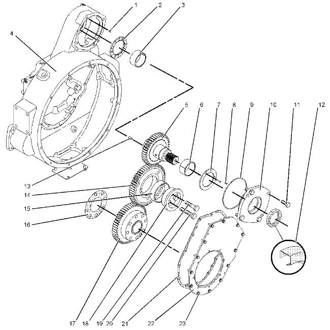
2. Remove bolts (23) , cover (22) , and gasket (21) . Remove crankshaft gear (17) from the crankshaft. Remove seal (16) .
3. Remove bolts (19) , bolt (20) , idler shaft (18) , and idler gear (14) .
4. Remove bearing (15) from idler gear (14) with Tooling (B) .
5. Remove lip seal (12) , bolts (11) , and adapter assembly (10) . Remove O-ring seal (9) , dowels (8) , thrust washer (7) , and bearing (6) from adapter assembly (10) .
6. Remove PTO shaft (5) from flywheel housing (4) . Remove dowel (13) .
7. Remove thrust washer (2) and dowels (1) .
Illustration 1 g01103652Previous Screen
Product: MOBILE HYD POWER UNIT
Model: 336E HVG MOBILE HYD POWER UNIT RBS
Configuration: 336E L HVG UHD Mobile Hydraulic Power Unit RBS00001-UP (MACHINE) POWERED BY C9.3 Engine
Disassembly and Assembly
C9.3
Engines for Caterpillar Built Machines
Rear Power Take-Off (RPTO) - Install
SMCS - 1165-012-RE
Installation Procedure
NOTICE
Keep all parts clean from contaminants.
Contaminants may cause rapid wear and shortened component life.
Shutdown SIS
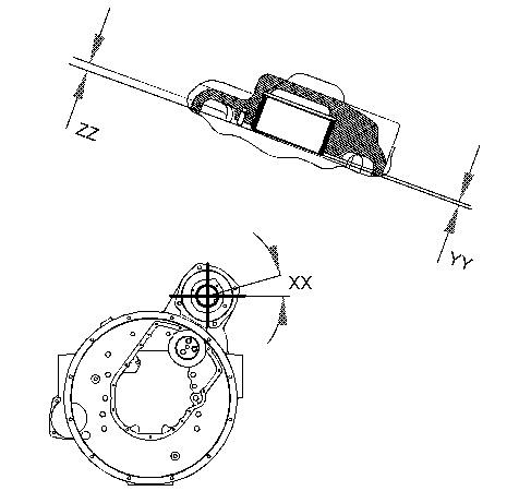
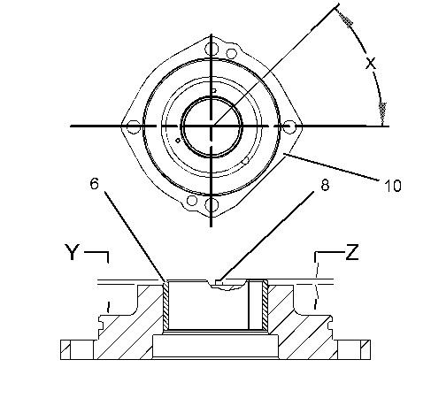
Illustration 4 g01103675
1. Use Tooling (B) to install bearing (3) in flywheel housing (4) . The bearing joint is located at an Angle (XX) that is 15 ± 3 degrees from the horizontal centerline. The oil hole in the bearing must align with the oil gallery in the flywheel housing. The bearing should extend beyond the surface of the flywheel housing by a Distance (YY) of 3.1 ± .5 mm (0.12 ± 0.02 inch).
2. Install dowels (1) in flywheel housing (4) . The dowels should extend beyond the surface of the flywheel housing by a Distance (ZZ) of 3.5 ± .2 mm (0.14 ± 0.01 inch).
3. Install thrust washer (2) into flywheel housing (4) .
4. Place adapter assembly (10) on the work surface. The outside face should be down. Install bearing (6) in adapter assembly (10) with Tooling (B) . The split in the bearing should be located at Angle (X) , which is 45 ± 10 degrees from the centerline of adapter assembly (10) . The bearing should extend beyond the surface of adapter assembly (10) by a Distance (Y) of 3.1 ± 0.5 mm (0.12 ± 0.02 inch).
5. Install dowels (8) and thrust washer (7) in adapter assembly (10) . The dowels should extend beyond the surface of adapter assembly (10) by a Distance (Z) of 3.5 ± 0.2 mm (0.14 ± 0.01 inch).
6. Install O-ring seal (9) on adapter assembly (10) .
7. Use Tooling (D) to install lip seal (12) . Lubricate lip seal (12) lightly with the lubricant that is being sealed. Lip seal (12) should be installed to a depth of 2.5 ± 0.5 mm (0.1 ± 0.02 inch).
8. Install PTO shaft (5) and adapter assembly (10) into flywheel housing (4) and install bolts (11) . Ensure that the flat side of adapter assembly (10) is against the flywheel housing. This will ensure that the oil passage is located toward the flywheel housing.
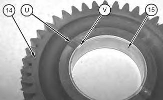
9. Install bearing (15) in idler gear (14) with Tooling (B) . Bearing Relief Groove (V) must line up with Relief Groove (U) in idler gear (14) within 2 degrees. Bearing (15) must not extend beyond either face of gear.
10. Install idler gear (14) on idler shaft (18) and bolts (19) and (20) . Install the shaft and gear assembly in the flywheel housing.
11. Install Tooling (A) in the crankshaft. Install seal (16) and crankshaft gear (17) .
12. Install gasket (21) , cover (22) , and bolts (23) .
End By: Install the crankshaft rear seal.
Shutdown SIS
Previous Screen
Product: MOBILE HYD POWER UNIT
Model: 336E HVG MOBILE HYD POWER UNIT RBS
Configuration: 336E L HVG UHD Mobile Hydraulic Power Unit RBS00001-UP (MACHINE) POWERED BY C9.3 Engine
Disassembly and Assembly
C9.3
Engines for Caterpillar Built Machines
Vibration Damper and Pulley - Remove and Install
SMCS - 1205-010
Removal Procedure
Illustration 1
g06119915
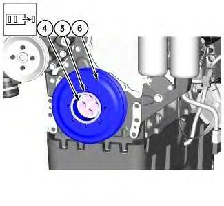
1. Remove bolts (1) and remove spacer (2). Remove vibration damper (3).
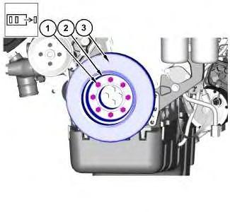
Illustration 2
g06119979
2. Remove bolts (4) and remove spacer (5). Remove pulley (6).
Installation Procedure
1. Install Vibration Damper (3) and Pulley (6) in the reverse order of removal.
a. Tighten bolts (4) to a torque of 200 ± 25 N·m (148 ± 18 lb ft).
b. Tighten bolts (1) to a torque of 55 ± 10 N·m (41 ± 7 lb ft).
Shutdown SIS
Previous Screen
Product: MOBILE HYD POWER UNIT
Model: 336E HVG MOBILE HYD POWER UNIT RBS
Configuration: 336E L HVG UHD Mobile Hydraulic Power Unit RBS00001-UP (MACHINE) POWERED BY C9.3 Engine
Disassembly and Assembly
C9.3
Engines for Caterpillar Built Machines
Crankshaft Front Seal - Remove
SMCS - 1160-011
Removal Procedure Table 1
Required Tools
Start By:
a. Remove the crankshaft vibration damper and pulley. Refer to Disassembly and Assembly, "Vibration Damper and Pulley - Remove and Install".
NOTICE
Keep all parts clean from contaminants.
Contaminants may cause rapid wear and shortened component life.
1. Use Tooling (B) to carefully drill three evenly spaced holes in crankshaft front seal (1).
2. Alternate between the drilled holes and use Tooling (A) to remove crankshaft front seal (1).
Shutdown SIS
Previous Screen
Product: MOBILE HYD POWER UNIT
Model: 336E HVG MOBILE HYD POWER UNIT RBS
Configuration: 336E L HVG UHD Mobile Hydraulic Power Unit RBS00001-UP (MACHINE) POWERED BY C9.3 Engine
Disassembly and Assembly
C9.3
Engines for Caterpillar Built Machines
Crankshaft Front Seal - Install
SMCS - 1160-012
Installation Procedure Table 1
Required Tools
Tool Part Number Part Description Qty
C 1U-7430 Front Seal Installer 1
NOTICE
Keep all parts clean from contaminants.
Contaminants may cause rapid wear and shortened component life.
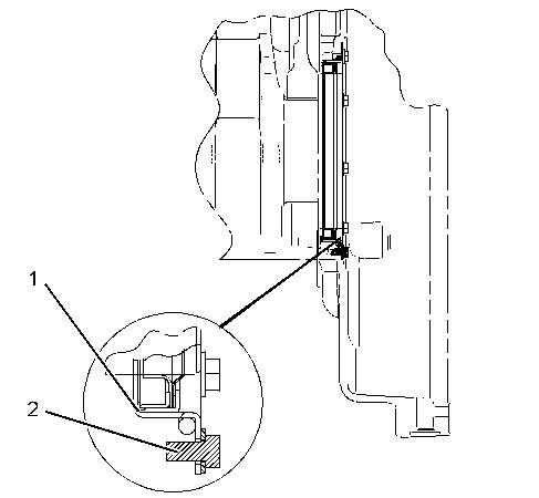
Illustration 1 g01138218
Note: The crankshaft seal is designed to be installed dry.
1. Use Tooling (C) to install crankshaft front seal (1).
End By:
a. Install the crankshaft vibration damper and pulley. Refer to Disassembly and Assembly, "Vibration Damper and Pulley - Remove and Install".
Shutdown SIS
Previous Screen
Product: MOBILE HYD POWER UNIT
Model: 336E HVG MOBILE HYD POWER UNIT RBS
Configuration: 336E L HVG UHD Mobile Hydraulic Power Unit RBS00001-UP (MACHINE) POWERED BY C9.3 Engine
Disassembly and Assembly
C9.3
Engines for Caterpillar Built Machines
Front Cover - Remove and Install
SMCS - 1166-010
Removal Procedure
Start By:
a. Remove vibration damper and pulley.
1. Remove bolt (1) and the belt tensioner (2). Remove bolts (3) and bolts (4). Remove stud bolt (5) and front remove cover (6) and the gasket.
Installation Procedure
1. Install the front cover (6) in the reverse order of removal.
Suggest:
If the above button click is invalid.
Please download this document first, and then click the above link to download the complete manual.
Thank you so much for reading

Shutdown SIS
Previous Screen
Product: MOBILE HYD POWER UNIT
Model: 336E HVG MOBILE HYD POWER UNIT RBS
Configuration: 336E L HVG UHD Mobile Hydraulic Power Unit RBS00001-UP (MACHINE) POWERED BY C9.3 Engine
Disassembly and Assembly
C9.3
Engines for Caterpillar Built Machines
Housing (Front) - Remove
SMCS - 1151-011
Removal Procedure
Start By:
a. Remove the crankshaft front seal.
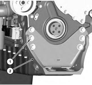
b. Remove the camshaft.
1. Remove bolts (1) and remove engine mount (2).