Shutdown SIS
Previous Screen
Product: EXCAVATOR
Model: 336D2 GC EXCAVATOR NBN
Configuration: 336D2 GC Excavator NBN00001-UP (MACHINE) POWERED BY C9 Engine
Disassembly and Assembly
330D, 336D, 336D2, 340D and 340D2 Excavators and 336D MHPU Mobile Hydraulic Power Unit Machine Systems
Piston Pump (Hydraulic Fan) - Assemble
SMCS - 1387-016-QP; 5070-016-HFN
Assembly Procedure
Table 1
Required Tools Tool
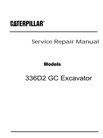
1. Lower the temperature of bearing cup (49). Install bearing cup (49).
2. Install lip seal (48).
3. Use Tooling (B) in order to install retaining ring (47).
4. Raise the temperature of bearing cone (46).
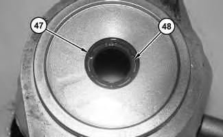 Illustration 2
g01212913
Illustration 3
g01213404
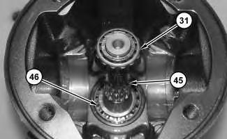
5. Install bearing cone (46) onto shaft (45).
Illustration 4
g01213405
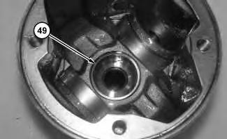
6. Install bearing cone (46), shaft (45), and bearing cone (31).
Illustration 2
g01212913
Illustration 3
g01213404
5. Install bearing cone (46) onto shaft (45).
Illustration 4
g01213405
6. Install bearing cone (46), shaft (45), and bearing cone (31).
Illustration 5 g01213407
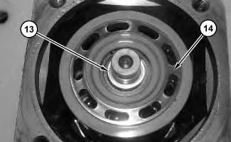
7. Lower the temperature of bearing cone (26). Install bearing cone (26).
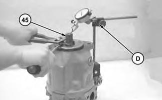
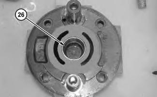
Illustration 6 g01212900
8. Position head (23) onto the housing.
9. Install bolts (22).
Illustration 7 g01213409
10. Use Tooling (D) in order to determine the end play of shaft (45).
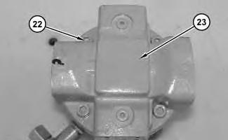
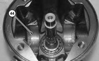 Illustration 8 g01212900
11. Remove bolts (22) and head (23).
Illustration 9 g01213405
12. Remove bearing cone (31).
Illustration 10 g01213433
13. Install bearings (44).
Illustration 8 g01212900
11. Remove bolts (22) and head (23).
Illustration 9 g01213405
12. Remove bearing cone (31).
Illustration 10 g01213433
13. Install bearings (44).
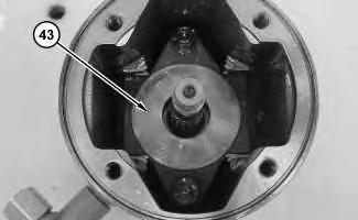
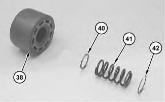
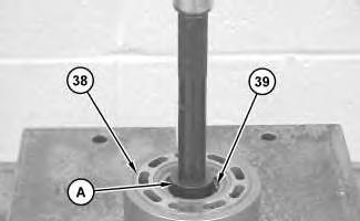 Illustration 11 g01212910
14. Install swashplate (43).
Illustration 12 g01373818
15. Install shim (40), spring (41), and shim (42) to barrel (38).
Illustration 13 g01212908
Illustration 11 g01212910
14. Install swashplate (43).
Illustration 12 g01373818
15. Install shim (40), spring (41), and shim (42) to barrel (38).
Illustration 13 g01212908
Improper assembly of parts that are spring loaded can cause bodily injury.
To prevent possible injury, follow the established assembly procedure and wear protective equipment.
16. Use Tooling (A), Tooling (B), and a suitable press in order to install retaining ring (39) into
 barrel (38).
Illustration 14
g01212907
17. Install pins (37) into barrel (38).
Illustration 15
g01212906
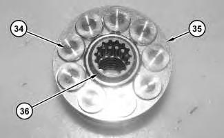
18. Install bearing (36), retainer (35), and pistons (34).
barrel (38).
Illustration 14
g01212907
17. Install pins (37) into barrel (38).
Illustration 15
g01212906
18. Install bearing (36), retainer (35), and pistons (34).
Note: Shim thickness was determined on Step 9.
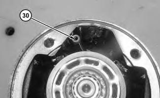
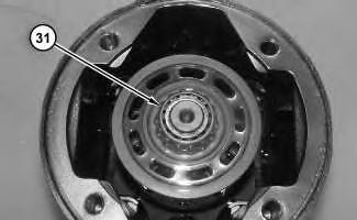
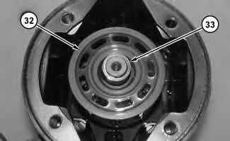 Illustration 16
g01212905
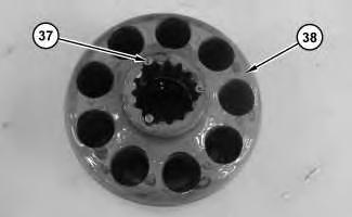
19. Install rotating group (32) and shim (33).
Illustration 17
g01212904
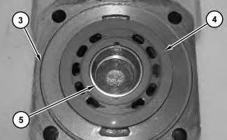
20. Install bearing cone (31).
Illustration 18
g01212903
21. Install piston (30).
Illustration 16
g01212905
19. Install rotating group (32) and shim (33).
Illustration 17
g01212904
20. Install bearing cone (31).
Illustration 18
g01212903
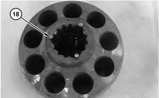
21. Install piston (30).
Illustration 19
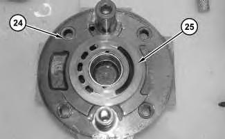
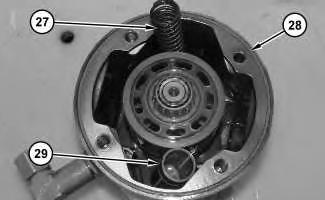
Illustration 20
Illustration 21
Improper assembly of parts that are spring loaded can cause bodily injury.
To prevent possible injury, follow the established assembly procedure and wear protective equipment.
24. Install head (23) and bolts (22).
Improper assembly of parts that are spring loaded can cause bodily injury.
To prevent possible injury, follow the established assembly procedure and wear protective equipment.
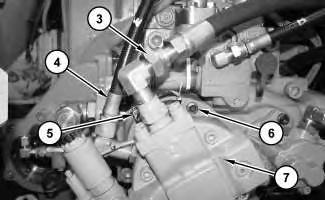
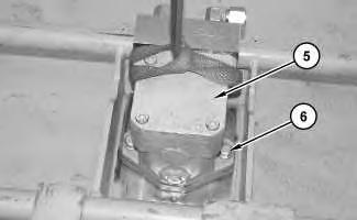
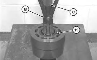
25. Install spool (15), poppet (16), spring (17), spring (18), shim (19), O-ring seal (20), and housing (21) into housing (2).
26. Install retainer (7), spring (8), retainer (9), spool (10), O-ring seal (12), backup ring (11), Oring seal (13), and cartridge (14).
27. Install screw (6) into housing (2).
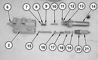 Illustration 22
g01212898
Illustration 22
g01212898
Illustration 23
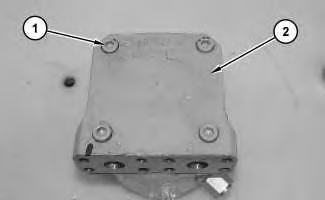
28. Install coil (4) and nut (5).
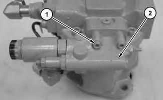
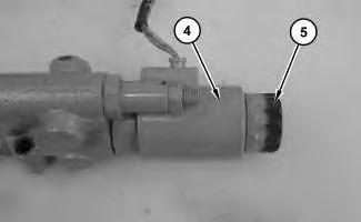
Illustration 24
29. Install O-ring seals (3).
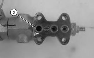
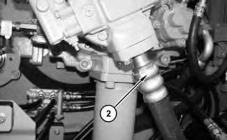
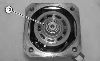
Illustration 25
30. Install controller (2) and bolts (1).
End By:
a. Install the piston pump. Refer to Disassembly and Assembly, "Piston Pump (Hydraulic Fan) - Install".
Copyright 1993 - 2020 Caterpillar Inc. All Rights Reserved. Private Network For SIS Licensees.
Fri Aug 7 23:47:09 UTC+0800 2020
Shutdown SIS
Previous Screen
Product: EXCAVATOR
Model: 336D2 GC EXCAVATOR NBN
Configuration: 336D2 GC Excavator NBN00001-UP (MACHINE) POWERED BY C9 Engine
Disassembly and Assembly
330D, 336D, 336D2, 340D and 340D2 Excavators and 336D MHPU Mobile Hydraulic Power Unit Machine Systems
Piston Pump (Hydraulic Fan) - Install
SMCS - 1387-012-QP; 5070-012-HFN
Installation Procedure
Note: Cleanliness is an important factor. Before assembly, all parts should be thoroughly cleaned in cleaning fluid. Allow the parts to air dry. Wiping cloths or rags should not be used to dry parts. Lint may be deposited on the parts which may cause later trouble. Inspect all parts. If any parts are worn or damaged, use new parts for replacement.
1.
Shutdown SIS
Previous Screen
Product: EXCAVATOR
Model: 336D2 GC EXCAVATOR NBN
Configuration: 336D2 GC Excavator NBN00001-UP (MACHINE) POWERED BY C9 Engine
Disassembly and Assembly
330D, 336D, 336D2, 340D and 340D2 Excavators and 336D MHPU Mobile Hydraulic Power Unit Machine Systems
Piston Motor (Hydraulic Fan) - Remove
SMCS - 1386-011-QP; 5058-011-FM
Removal Procedure
Start By:
a. Remove the fan. Refer to Disassembly and Assembly, "Fan - Remove".
Note: Cleanliness is an important factor. Before the disassembly procedure, the exterior of the component should be thoroughly cleaned. This will help to prevent dirt from entering the internal mechanism.
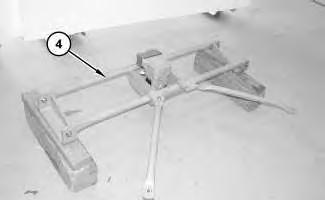
1. Bend locking tabs (1) backward.
2. Remove bolts (2) and hub (3).
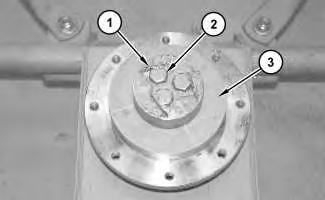
Illustration 2
g01207416
3. Use a suitable lifting device to position fan motor assembly (4) onto suitable cribbing. The weight of fan motor assembly (4) is approximately 68 kg (150 lb).
Illustration 3
g01207418
4. Attach a suitable lifting device to piston motor (5). The weight of piston motor (5) is approximately 23 kg (50 lb).
5. Remove bolts (6) and fan motor (5).
Copyright 1993 - 2020 Caterpillar Inc.
All Rights Reserved.
Private Network For SIS Licensees.
Fri Aug 7 23:49:00 UTC+0800 2020
Shutdown SIS
Previous Screen
Product: EXCAVATOR
Model: 336D2 GC EXCAVATOR NBN
Configuration: 336D2 GC Excavator NBN00001-UP (MACHINE) POWERED BY C9 Engine
Disassembly and Assembly
330D, 336D, 336D2, 340D and 340D2 Excavators and 336D MHPU Mobile Hydraulic Power Unit Machine Systems
Piston Motor (Hydraulic Fan) - Disassemble
SMCS - 1386-015-QP; 5058-015-FM; 5058-015-HFN
Disassembly Procedure
Table 1
Required Tools Tool
A 9S-9152
B 1P-1861 Retaining Ring Pliers 1
C 1P-0510 Driver Gp 1
Start By:
a. Remove the piston motor. Refer to Disassembly and Assembly, "Piston Motor (Hydraulic Fan) - Remove".
Personal injury can result from being struck by parts propelled by a released spring force.
Make sure to wear all necessary protective equipment.
Follow the recommended procedure and use all recommended tooling to release the spring force.
1. Remove bolts (1) and head (2).
Illustration 2
2. Remove O-ring seal (3), port plate (4), and bearing cup (5).
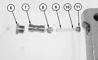
Illustration 3
Personal injury can result from being struck by parts propelled by a released spring force.
Make sure to wear all necessary protective equipment.
Follow the recommended procedure and use all recommended tooling to release the spring force.
 3. Remove plug (6), sleeve (7), poppet (8), spring (9), poppet (10), and O-ring seal (11).
Illustration 4
g01207279
4. Remove bearing cone (12).
Illustration 5
g01207280
5. Remove shim (13) and rotating group (14).
3. Remove plug (6), sleeve (7), poppet (8), spring (9), poppet (10), and O-ring seal (11).
Illustration 4
g01207279
4. Remove bearing cone (12).
Illustration 5
g01207280
5. Remove shim (13) and rotating group (14).
6. Remove pistons (15) and retainer (16).
7. Remove bearing (17).
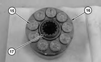 Illustration 6
g01207281
Illustration 7
g01207282
8. Remove pins (18).
Illustration 8
g01207283
Illustration 6
g01207281
Illustration 7
g01207282
8. Remove pins (18).
Illustration 8
g01207283
Personal injury can result from being struck by parts propelled by a released spring force.
Make sure to wear all necessary protective equipment.
Follow the recommended procedure and use all recommended tooling to release the spring force.
9. Use Tooling (C) and Tooling (B) in order to remove retaining ring (19).
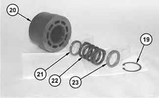
10. Remove shim (23), spring (22), and shim (21).
11. Remove swashplate (24) and shaft (25).
Illustration 9 g01207284 Illustration 10 g01207285Illustration 11
12. Use Tooling (A) in order to remove bearing cone (26) from shaft (25).
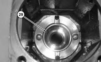
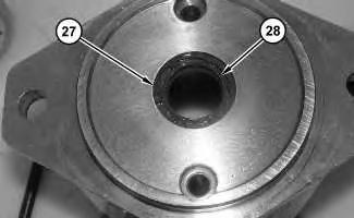
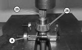
Illustration 12
13. Use Tooling (C) in order to remove retaining ring (27).
14. Remove lip seal (28).
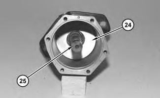
Illustration 13
15. Remove bearing cup (29).
g01207287 g01207286 g01207288Shutdown SIS
Previous Screen
Product: EXCAVATOR
Model: 336D2 GC EXCAVATOR NBN
Configuration: 336D2 GC Excavator NBN00001-UP (MACHINE) POWERED BY C9 Engine
Disassembly and Assembly
330D, 336D, 336D2, 340D and 340D2 Excavators and 336D MHPU Mobile Hydraulic Power Unit Machine Systems
Piston Motor (Hydraulic Fan) - Assemble
SMCS - 1386-016-QP; 5058-016-FM; 5058-016-HFN
Assembly Procedure Table 1
Required Tools
2. Install lip seal (28).
3. Use Tooling (C) in order to install retaining ring (27).
4. Raise the temperature of bearing cone (26).
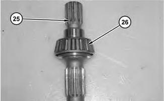 Illustration 2
g01207286
Illustration 3
g01207624
5. Install bearing cone (26) onto shaft (25).
Illustration 4
g01207285
6. Install shaft (25) and swashplate (24).
Illustration 2
g01207286
Illustration 3
g01207624
5. Install bearing cone (26) onto shaft (25).
Illustration 4
g01207285
6. Install shaft (25) and swashplate (24).
Improper assembly of parts that are spring loaded can cause bodily injury.
To prevent possible injury, follow the established assembly procedure and wear protective equipment.
7. Install shim (21), spring (22), and shim (23).
8. Use Tooling (C) and Tooling (B) in order to install retaining ring (19).
Illustration 5
g01207283
Illustration 6
g01207284
Illustration 7 g01207282
9. Install pins (18).
Illustration 8 g01207281
10. Install bearing (17).
11. Install pistons (15) and retainer (16).
Illustration 9 g01207280
12. Install rotating group (14) and shim (13).
Suggest:
If the above button click is invalid.
Please download this document first, and then click the above link to download the complete manual.
Thank you so much for reading

Improper assembly of parts that are spring loaded can cause bodily injury.
To prevent possible injury, follow the established assembly procedure and wear protective equipment.
Illustration 10
g01207279
13. Install bearing cone (12).
Illustration 11
g01207278
14. Install O-ring seal (11), poppet (10), spring (9), poppet (8), sleeve (7), and plug (6).