Previous Screen
Product: EXCAVATOR
Model: 330-A L EXCAVATOR 5YM
Configuration: 330, 330L Excavators 5YM00001-UP (MACHINE)
Disassembly and Assembly
3304B and 3306B Engines for Caterpillar Built Machines
Compression Brake - Install
SMCS - 1119-012
Installation Procedure
NOTICE
Keep all parts clean from contaminants.
Contaminants may cause rapid wear and shortened component life.
Shutdown SIS
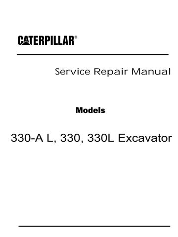
Illustration 1
g00471010
1. Install Compression Brake (B) and oil tube (4) .
2. Install Compression Brake (A) .
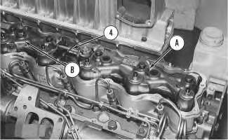
Illustration 2 g00471009
3. Connect wires (3) and (2). Install four bolts (1) .
End By: Install the valve mechanism cover. Refer to Disassembly and Assembly, "Valve Mechanism Cover - Remove and Install".
Copyright 1993 - 2020 Caterpillar Inc. All Rights Reserved. Private Network For SIS Licensees.
Shutdown SIS
Previous Screen
Product: EXCAVATOR
Model: 330-A L EXCAVATOR 5YM
Configuration: 330, 330L Excavators 5YM00001-UP (MACHINE)
Disassembly and Assembly
3304B and 3306B Engines for Caterpillar Built Machines
Rocker Shaft and Pushrod - Remove
SMCS - 1102-011; 1208-011
Removal Procedure
Start By:
A. Remove the valve mechanism cover. Refer to Disassembly and Assembly, "Valve Mechanism Cover - Remove and Install".
NOTICE
Keep all parts clean from contaminants.
Contaminants may cause rapid wear and shortened component life.
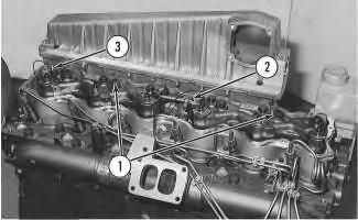
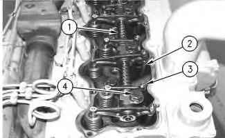
g00539802
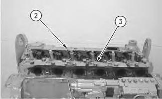
1. Remove six bolts (3) and rocker shaft assembly (2). Remove the O-ring seal from the rear rocker shaft support.
2. Put identification marks on pushrods (1) in order to identify the location of the pushrods in the engine. Remove pushrods (1) from the engine. Repeat this process for each pushrod.
Shutdown SIS
Previous Screen
Product: EXCAVATOR
Model: 330-A L EXCAVATOR 5YM
Configuration: 330, 330L Excavators 5YM00001-UP (MACHINE)
Disassembly and Assembly
3304B and 3306B Engines for Caterpillar Built Machines
Rocker Shaft - Disassemble
SMCS - 1102-015
Disassembly Procedure
Start By:
A. Remove the rocker shaft and pushrods. Refer to Disassembly and Assembly, "Rocker Shaft and Pushrods - Remove".
NOTICE
Keep all parts clean from contaminants.
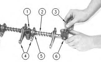
Contaminants may cause rapid wear and shortened component life. Illustration
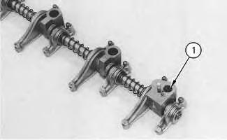
1. Remove O-ring seal (1) from the rear support bracket.
Note: Replace the O-ring seal when the head bolt is removed from the rear rocker shaft support.
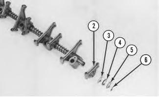
2. Remove retainer ring (6), washer (5), spring (4), washer (3) and rocker arm (2). Note the number of washers (3) that are used at both ends of the shaft. Remove rocker arms (2) from each end of the rocker shaft.
3. Remove the pin from the rear rocker shaft support (7) with a hammer and a suitable punch. Remove rear rocker shaft support (7) .
4. Remove the remaining rocker arms, springs, washers and rocker shaft supports.
5. Remove the plugs from each end of the shaft, if necessary.
 Illustration 2
g00490027
Illustration 3
g00449687
Illustration 2
g00490027
Illustration 3
g00449687
Previous Screen
Product: EXCAVATOR
Model: 330-A L EXCAVATOR 5YM
Configuration: 330, 330L Excavators 5YM00001-UP (MACHINE)
Disassembly and Assembly
3304B and 3306B Engines for Caterpillar Built Machines
Rocker Shaft - Assemble
SMCS - 1102-016
Assembly Procedure
NOTICE
Keep all parts clean from contaminants.
Contaminants may cause rapid wear and shortened component life.
NOTICE
Care must be taken to ensure that fluids are contained during performance of inspection, maintenance, testing, adjusting and repair of the product. Be prepared to collect the fluid with suitable containers before opening any compartment or disassembling any component containing fluids.
Refer to Special Publication, NENG2500, "Caterpillar Tools and Shop Products Guide" for tools and supplies suitable to collect and contain fluids on Caterpillar products.
Dispose of all fluids according to local regulations and mandates.
Illustration 1
1. Install rocker arms (4), supports (1), washer (5) and springs (2) on the rocker shaft.
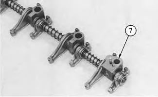
2. Install rear rocker shaft support (6) on the rocker shaft. Ensure that the hole in the rear rocker shaft support is aligned with the hole in the rocker shaft.
3. Install pin (3) through the rocker shaft support and the rocker shaft with a hammer.
4. Pin (3) must extend 9.60 mm (.378 inch) above the rocker shaft support.
g00449863 Illustration 2 g00449625Illustration 3
g00449628
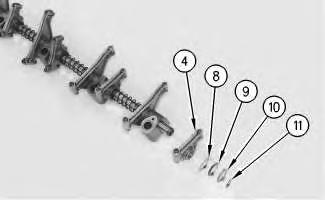
5. Install O-ring seal (7). Install rocker arm (4), washer (8), springs (9), washer (10) and retainer ring (11) .
Note: Make sure that the correct number of washers (8) are installed on the shaft.
6. Install the plugs in each end of the rocker shaft if the plugs were removed.
End By: Install the rocker shaft and pushrods. Refer to Disassembly and Assembly, "Rocker Shaft and Pushrods - Install".
Previous Screen
Product: EXCAVATOR
Model: 330-A L EXCAVATOR 5YM
Configuration: 330, 330L Excavators 5YM00001-UP (MACHINE)
Disassembly and Assembly
3304B and 3306B Engines for Caterpillar Built Machines
Rocker Shaft and Pushrod - Install
SMCS - 1102-012; 1208-012
Installation Procedure
NOTICE
Keep all parts clean from contaminants.
Contaminants may cause rapid wear and shortened component life.
Shutdown SIS
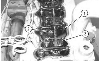
2. Install rocker shaft assembly (1) in position on the cylinder head.
NOTICE
Ensure that the dowels on each end of the rocker shaft assembly are in alignment with the holes in the cylinder head.
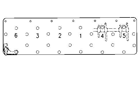
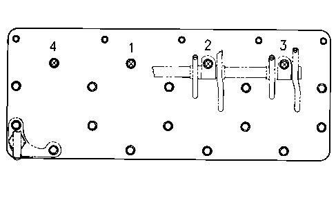
Illustration 2 g00591852
3304B torque sequence
Illustration 3 g00544706
3306B torque sequence
Note: Replace the O-ring seal when the bolt toward the rear of the engine is installed in the rocker shaft support.
3. Apply 6V-4876 Lubricant on the threads of six bolts (4) except for the bolt that passes through the rear rocker shaft support (bolt (6) in Illustration 3). Install six bolts (4) in the rocker shaft assembly.
4. Refer to Illustration 3. Tighten six bolts (4) for the rocker shaft, as follows:
a. Tighten all the bolts in the numerical sequence to a torque of 155 N·m (115 lb ft).
b. Tighten all the bolts in the numerical sequence to a torque of 250 ± 17 N·m (185 ± 13 lb ft).
c. Tighten all the bolts again in the numerical sequence to a final torque of 250 ± 17 N·m (185 ± 13 lb ft).
5. The assembled length of the springs at both ends of the rocker shaft must be 1.50 ± 0.25 mm (.059 ± .010 inch). Remove the washers or install the washers behind the springs to change the assembled length of the springs.
6. Adjust the inlet valve lash to 0.38 ± 0.08 mm (.015 ± .003 inch) and adjust the exhaust valve lash to 0.64 ± 0.08 mm (.025 ± .003 inch). Refer to Testing and Adjusting, "Air Inlet and Exhaust System" for more information on setting the valve lash. Tighten the locknuts for the adjusting screws (3) to a torque of 29 ± 7 N·m (21 ± 5 lb ft). Refer to Specifications, "Valve Rocker Arms and Lifters".
End By:
a. Install the valve mechanism cover. Refer to Disassembly and Assembly, "Valve Mechanism Cover - Remove and Install". Copyright 1993 - 2020 Caterpillar Inc.
Previous Screen
Product: EXCAVATOR
Model: 330-A L EXCAVATOR 5YM
Configuration: 330, 330L Excavators 5YM00001-UP (MACHINE)
Disassembly and Assembly
3304B and 3306B Engines for Caterpillar Built Machines
Cylinder Head - Remove
SMCS - 1100-011
Removal Procedure
Start By:
A. Remove the fuel injection lines. Refer to Disassembly and Assembly, "Fuel Injection Lines - Remove and Install".
B. Remove the exhaust manifold. Refer to Disassembly and Assembly, "Exhaust ManifoldRemove and Install".
C. Remove the rocker shaft and pushrods. Refer to Disassembly and Assembly, "Rocker Shaft and Pushrods - Remove".
NOTICE
Keep all parts clean from contaminants.
Contaminants may cause rapid wear and shortened component life.
NOTICE
Care must be taken to ensure that fluids are contained during performance of inspection, maintenance, testing, adjusting and repair of the machine. Be prepared to collect the fluid with suitable containers before opening any compartment or disassembling any component containing fluids.
Refer to Special Publication, NENG2500, "Caterpillar Tools and Shop Products Guide", for tools and supplies suitable to collect and contain fluids in Caterpillar machines.
Dispose of all fluids according to local regulations and mandates.
1. Loosen hose clamp (2) on the hose that connects the oil cooler to water pump elbow (1) .
2. Remove two bolts (3) that fasten water pump elbow (1) to the cylinder head. Remove two bolts (4) that fasten water pump elbow (1) to the water pump.

3. Carefully remove water pump elbow (1) and the gaskets from the engine.
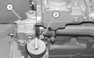 Illustration 1
g00505124
Illustration 2
g00505164
Illustration 1
g00505124
Illustration 2
g00505164
4. Disconnect tube (5) from the inlet manifold.
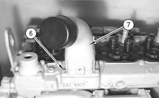
5. Remove four bolts (6) and remove air inlet pipe (7) .
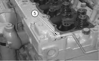 Illustration 3 g00538842
Illustration 4 g00538845
Illustration 5
g00541454
Illustration 3 g00538842
Illustration 4 g00538845
Illustration 5
g00541454
Do not set the cylinder head on a hard, flat surface. Damage may occur to the fuel injection nozzle tips.
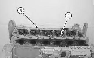
6. Remove all bolts (8) and (9) that hold the cylinder head to the cylinder block.
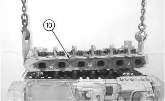
Illustration 6 g00505311
7. Attach the proper lifting device in order to remove cylinder head (10) from the engine. Remove cylinder head (10) from the engine. The weight of cylinder head (10) is approximately 95 kg (210 lb).
Previous Screen
Product: EXCAVATOR
Model: 330-A L EXCAVATOR 5YM
Configuration: 330, 330L Excavators 5YM00001-UP (MACHINE)
Disassembly and Assembly
3304B and 3306B Engines for Caterpillar Built Machines
Cylinder Head - Install
SMCS - 1100-012
Installation Procedure
NOTICE
Keep all parts clean from contaminants.
Contaminants may cause rapid wear and shortened component life.
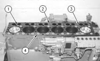
Note: When the cylinder head is removed, a new spacer plate gasket must be installed. Refer to Disassembly and Assembly, "Spacer Plate - Remove and Install".
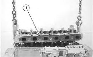
1. Ensure that the surface of the cylinder head is clean and dry. Install a new dry cylinder head gasket onto the cylinder block.
2. Fasten the proper lifting device to cylinder head (1). Put cylinder head (1) in position on the cylinder block. Remove the lifting device after cylinder head (1) is positioned.
3. Apply clean engine oil to the threads and the washer faces of cylinder head bolts (2) and (3). Install cylinder head bolts (2) and (3). Tighten the cylinder head bolts finger tight.
Note: Do not tighten the cylinder head bolts at this time.
4. Install pushrods (4). Make sure that the pushrods are installed in the original location and that the pushrods are seated correctly in the valve lifters.
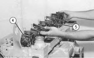
5. Loosen the adjusting screws on rocker arms (5) for valve clearance. This will prevent a bent valve or a broken pushrod during installation.
6. Install a new O-ring seal in the rear rocker arm support.
7. Apply clean engine oil to all the rocker shaft bolts except bolt (25). Refer to illustration 5.
8. Put rocker shaft assembly (5) in position on the cylinder head. Make sure that the dowels in the rocker shaft supports are aligned with the dowel holes in the cylinder head.
9. Ensure that the rocker arms are aligned with the pushrods and install the rocker shaft mounting bolts. Tighten the rocker shaft mounting bolts finger tight.
Illustration 2 g00541497 Illustration 3 g005114933304B torque sequence
10. Tighten the cylinder head bolts by hand, as follows:
a. Tighten all the bolts (1 through 18) in the numerical sequence to a torque of 150 ± 15 N·m (115 ± 12 lb ft).

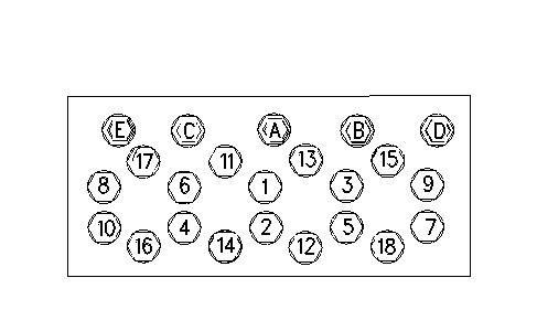
b. Tighten all the bolts (1 through 18) again in the numerical sequence to a torque of 250 ± 17 N·m (185 ± 13 lb ft).
c. Tighten all the bolts (1 through 18) again in the numerical sequence to a final torque of 250 ± 17 N·m (185 ± 13 lb ft).
d. Tighten all the remaining bolts (A through E) to a torque of 43 ± 7 N·m (32 ± 5 lb ft).
Illustration 4 g00602759Illustration 5 g00328807
3306B torque sequence
11. Tighten the cylinder head bolts by hand, as follows:

a. Tighten all the bolts (1 through 26) in the numerical sequence to a torque of 150 ± 15 N·m (115 ± 12 lb ft).
b. Tighten all the bolts (1 through 26) in the numerical sequence to a torque of 250 ± 17 N·m (185 ± 13 lb ft).
c. Tighten all the bolts (1 through 26) again in the numerical sequence to a final torque of 250 ± 17 N·m (185 ± 13 lb ft).
d. Tighten all the remaining bolts (A through G) to a torque of 43 ± 7 N·m (32 ± 5 lb ft).
12. Adjust the inlet valve lash to 0.38 mm (.015 inch) and the exhaust valve lash to 0.64 mm (.025 inch). Tighten the locknuts for the adjusting screws to a torque of 29 ± 7 N·m (22 ± 5 lb ft). Refer to the Testing and Adjusting, "Air Inlet and Exhaust System" topic for additional information on valve lash adjustments.
13. Put the gasket and air inlet pipe (7) in position on the cylinder head. Install four bolts (6) to fasten air inlet pipe (7) to the cylinder head.
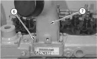 Illustration 6
g00511911
Illustration 7
g00541522
Illustration 6
g00511911
Illustration 7
g00541522
14. Connect tube (8) to the inlet manifold.
Illustration 8
15. Put the gaskets and water pump elbow (11) in position on the engine. Install two bolts (9) that fasten water pump elbow (11) to the cylinder head. Install two bolts (10) that fasten water pump elbow (11) to the water pump.
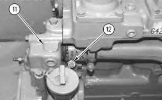
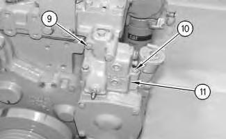
Illustration 9
16. Tighten hose clamp (12).
End By:
a. Install the valve mechanism cover. Refer to Disassembly and Assembly, "Valve Mechanism Cover - Remove and Install".
b. Install the exhaust manifold. Refer to Disassembly and Assembly, "Exhaust ManifoldRemove and Install".
c. Install the fuel injection lines. Refer to Disassembly and Assembly, "Fuel Injection LinesRemove and Install".
Copyright 1993 - 2020 Caterpillar Inc. All Rights Reserved.
g00541524 g00541527Previous Screen
Product: EXCAVATOR
Model: 330-A L EXCAVATOR 5YM
Configuration: 330, 330L Excavators 5YM00001-UP (MACHINE)
Disassembly and Assembly
3304B and 3306B Engines for Caterpillar Built Machines
Spacer Plate - Remove and Install
SMCS - 1221-010
Removal Procedure
Start By:
A. Remove the cylinder head. Refer to Disassembly and Assembly, "Cylinder HeadRemove".
NOTICE
Keep all parts clean from contaminants.
Contaminants may cause rapid wear and shortened component life. Illustration
g00540847
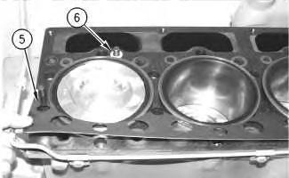
1. Remove O-ring seal (1), water seals (3) and water directors (4) from spacer plate (2) .
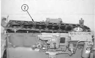
Illustration 2
NOTICE
Do not damage the dowels as the spacer plate is removed.
2. Remove spacer plate (2) from the cylinder head.
Illustration 3
3. Remove O-ring seal (6) and spacer plate gasket (5) from the cylinder head.
Installation Procedure
 g00540857
g00540895
g00540857
g00540895
Suggest:
If the above button click is invalid.
Please download this document first, and then click the above link to download the complete manual.
Thank you so much for reading

Keep all parts clean from contaminants.
Contaminants may cause rapid wear and shortened component life.
1. Thoroughly clean the mating surfaces between the spacer plate and the cylinder block.
2. Install new spacer plate gasket (5) and new O-ring seal (6) .
Note: If the dowels in the cylinder block have been removed for any reason, the overall height of the installation is 16.0 ± 5.0 mm (.63 ± .20 inch).
Note: Both surfaces of the spacer plate, spacer plate gasket and the top of the cylinder block must be clean and dry. Do not use any gasket adhesive or other substances on these surfaces.