Assembly Procedure
Note: Cleanliness is an important factor. Before assembly, all parts should be thoroughly cleaned in cleaning fluid. Allow the parts to air dry. Wiping cloths or rags should not be used to dry parts. Lint may be deposited on the parts which may cause later trouble. Inspect all parts. If any parts are worn or damaged, use new parts for replacement. All disassembly and all assembly procedures must be performed on a clean work surface and in a clean hydraulic area. Keep cleaned parts covered and protected at all times.
Note: O-ring seals, gaskets, and seals should always be replaced. A used O-ring seal may not have the same sealing properties as a new O-ring. Use Tooling (K) during the assembly procedure.
Note: Apply a light film of hydraulic oil to all components before assembly.
Note: Some of the images that are in this procedure do not show the sprocket assembly that is attached to the final drive housing. If necessary, the weights that are given include the weight of the sprocket assembly.
1. Apply Tooling (P) to the outer diameter of the bearings.


2. Use a suitable press to Install bearings (40) and (41). Make sure that bearing (41) and bearing (40) contact the counterbore in housing (36).
3. Use Tooling (N) to install Duo-Cone seal (39B).
4. Use Tooling (N) to install Duo-Cone seal (39A) onto housing (38).
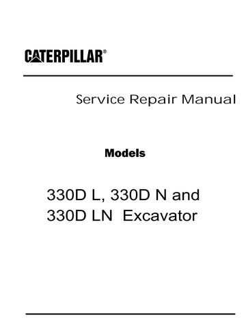
Illustration 1 g01147975 Illustration 2 g01147981 Illustration 3 g011479305. Use Tooling (E) and a suitable lifting device to install housing (36) onto housing (38). The weight of housing (36) is approximately 100 kg (220 lb).
6. Remove Tooling (E) from housing (36).
Illustration 4 g01147724
7. Install stopper plate (35). Do not tighten stopper plate assembly (35) at this time.

Note: Stopper plate (35) will secure housing (36) to housing (38).
8. Install Tooling (E) and a suitable lifting device to housing (36). The combined weight of housing assembly (36) and (38) is approximately 120 kg (265 lb). Install housing assembly (36) and (38) in a suitable press.

9. Remove stopper plate (35).
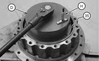
Illustration 5 g01147727
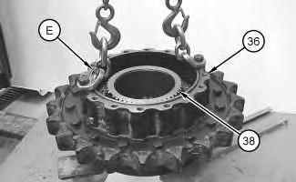
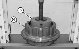
10. Assemble Tooling (D), as shown.
11. Install Tooling (D) into housing (36), as shown.
12. Apply a force of 4000 kg (8818 lb) to the top of Tooling (D). Rotate housing (36) to seat the bearings.
13. Reduce the force on the top of Tooling (D) to 3000 kg (6615 lb).

14. Use Tooling (H) to take a measurement in three locations. Average the three measurements and record the average measurement as Dimension (W).
15. Remove Tooling (D).
16. Separate Tooling (D).
Illustration 6 g01147731 Illustration 7 g01147737Illustration 8 g01147743
17. Use a micrometer to measure the thickness at three locations of the spacer from Tooling (D). Record the average measurement as Dimension (X).
Illustration 9 g01147742
18. Use a micrometer to measure the thickness at three locations of stopper plate (35). Record the average measurement as Dimension (Y).

19. Subtract Dimension (X) from Dimension (Y) and record this figure as Dimension (Z).
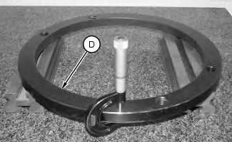 Illustration 10
g01147724
Illustration 10
g01147724
20. Install stopper plate (35) onto housing (38). Do not tighten stopper plate (35) at this time. Stopper plate (35) will secure the final drive assembly while the final drive assembly is repositioned onto Tooling (A).
21. Use Tooling (E) and a suitable lifting device to reposition the final drive assembly onto Tooling (A). The combined weight of housing assembly (36) and (38) is approximately 120 kg (265 lb).
22. Secure the final drive assembly to Tooling (A).
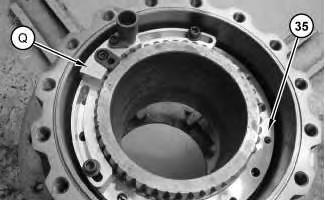
Illustration 11
23. Secure the spanner socket from Tooling (D) to stopper plate (35).
24. to determine the final bearing preload, add Dimension (W) to Dimension (Z) and record this figure as Dimension (V).
25. Use Tooling (H) to measure the distance in three locations.
26. Tighten stopper plate (35) until the average of the measurements is equal to Dimension (V).
27. Remove Tooling (D).
Illustration 12
28. Install Tooling (Q) and a suitable vacuum onto stopper plate (35).
g01148004 g01372092Illustration 13 g01147789
29. Use a suitable drill and Tooling (Q) to drill a hole to the depth of 15 mm (0.6 inch) in the stopper plate and in housing (38).
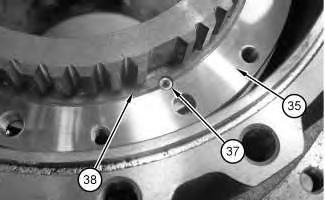
Illustration 14 g01147796
30. Install dowel (37).
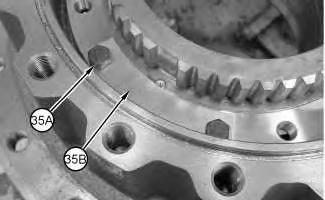
Illustration 15 g01147650
31. Apply Tooling (R) to bolts (35A). Install plate (35B) and bolts (35A).
32. Repeat Steps 28 through 31 for the opposite side of stopper plate (35).
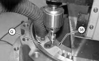
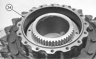

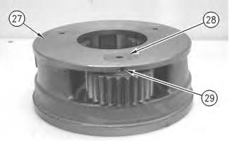 Illustration 16 g00781807
33. Install O-ring seal (34) on housing (36).
Illustration 17 g00781730
34. Install gear (33) on housing (36).
Illustration 18 g00781719
35. Assemble carrier assembly (27), as follows.
Illustration 16 g00781807
33. Install O-ring seal (34) on housing (36).
Illustration 17 g00781730
34. Install gear (33) on housing (36).
Illustration 18 g00781719
35. Assemble carrier assembly (27), as follows.
Illustration 19 g00781607
a. Use a deburring tool to remove the metal burr from the openings in the carrier.
b. Install two bearings (31) in planetary gear (32).
c. Install thrust washers (30) and planetary gear (32) in the carrier assembly.
d. Install planetary shaft (28) in the carrier assembly.
e. Align the split in spring pin (29) to the top or to the bottom. Make a stake mark on each side of the spring pin hole in the carrier. Each stake mark should be approximately 1.50 mm (0.059 inch) from the outside diameter of the spring pin hole.

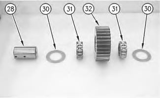
Illustration 20 g00903073
36. Repeat Steps 35.a through 35.e to install the other two planetary gears in the carrier.
f. Drive spring pin (29) into planetary shaft (28) with a hammer and a punch.Illustration 21 g00781559
37. Use two people to install carrier assembly (27) in gear (33). The weight of carrier assembly (27) is approximately 38 kg (85 lb).
Illustration 22
38. Install spacer (26). Install gear (25).
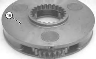
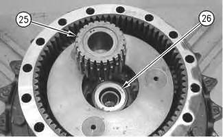
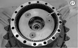
Illustration 23
39. Assemble carrier assembly (19), as follows.
g00781529 g01148010Illustration 24 g00781516
a. Use a deburring tool to remove the metal burr from the openings in the carrier.
b. Install bearing (23) in planetary gear (24).
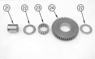
c. Install thrust washers (22) and planetary gear (24) in the carrier assembly.
d. Install planetary shaft (21) in the carrier assembly.
Illustration 25 g00903073 e. Drive spring pin (20) into planetary shaft (21) with a hammer and a punch.f. Align the split in the spring pin to the top or to the bottom. Make a stake mark on each side of the spring pin hole in the carrier. Each stake mark should be approximately 1.50 mm (0.059 inch) from the outside diameter of the spring pin hole.

g. Repeat Steps 39.a through 39.f to install the other two planetary gears in the carrier.
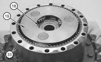
40. Install carrier assembly (19) into gear (33).
41. Install retaining ring (18).
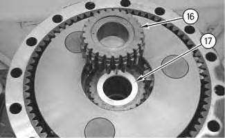
Illustration 26 g00879368 Illustration 27 g01148011 Illustration 28 g0078141242. Install spacer (17). Install gear (16).
Note: Make sure that the oil passages in the shafts are oriented toward the center of carrier assembly (15).

43. Raise the temperature of carrier assembly (15). Lower the temperature of the shafts. Install the shafts into carrier assembly (15) until the groove of the shafts is at Dimension (A). Dimension (A) equals 25.00 ± 0.10 mm (0.984 ± 0.004 inch).
44. Make eight stake marks at distance of Dimension (C) from each shaft. Dimension (C) equals 2.0 ± 1.0 mm (0.08 ± 0.04 inch). The width of each stake mark should be equal to Dimension (B). Dimension (B) equals 4.0 ± 1.0 mm (0.16 ± 0.04 inch).
Illustration 29 g0138959845. Assemble carrier assembly (15), as follows.
a. Install carrier assembly in position on gear (16).
b. Install retaining ring (14) onto gear (16).
c. Install washer (11). Install bearing assembly (13). Install gear (12). Install washer (11). Install retaining ring (10) with Tooling (C).
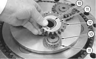
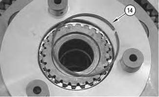
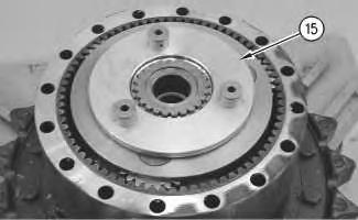 Illustration 30 g00781407
Illustration 31 g00781401
Illustration 32 g00780432
Illustration 30 g00781407
Illustration 31 g00781401
Illustration 32 g00780432
d. Repeat Steps 45.a through 45.c for the other two planetary gears.
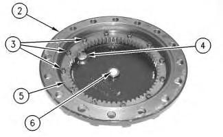
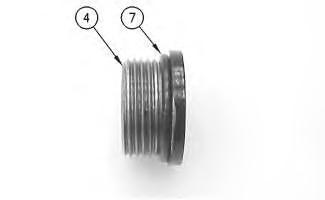
 Illustration 33 g00780428
46. Install spacer (9). Install gear (8).
Illustration 34 g00879365
47. Install O-ring seal (7) on plugs (4).
Illustration 35 g00879362
48. Install plugs (4) and spacer (6) in cover (2).
Illustration 33 g00780428
46. Install spacer (9). Install gear (8).
Illustration 34 g00879365
47. Install O-ring seal (7) on plugs (4).
Illustration 35 g00879362
48. Install plugs (4) and spacer (6) in cover (2).
49. Position gear (5). Install bolts (3).
Illustration 36 g00708090
Illustration 37 g00708089
50. Place a piece of solder in the center of gear (8).

Note: You may need to apply some grease to the solder to keep the solder in position on gear (8).
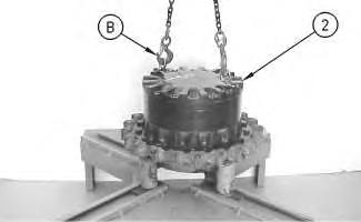
51. Use Tooling (B) and a suitable lifting device to Install cover (2). The weight of cover (2) is approximately 32 kg (70 lb).
52. Install four bolts (1) at 90 degrees from each other. Tighten bolts (1) in a crisscross pattern to a torque of 420 ± 60 N·m (310 ± 44 lb ft). Turn bolts (1) anadditional60 ± 5 degrees.
53. Remove bolts (1).
54. Use Tooling (B) and a suitable lifting device to remove cover (2). The weight of cover (2) is approximately 32 kg (70 lb).
55. Use a micrometer to measure the thickness of the solder. Record this measurement to determine the thickness of the shims for plate (6). Adjust the shims to obtain a clearance of 1.000 + 1.000 mm (0.0394 + 0.0394 inch) between plate (6) and gear (8).
56. Apply Tooling (M) to the mating surfaces of cover (2) and the housing.
57. Use Tooling (B) and a suitable lifting device to Install cover (2). The weight of cover (2) is approximately 32 kg (70 lb).
58. Apply Tooling (R) to bolts (1). Install bolts (1) and the washers. Tighten bolts (1) in a crisscross pattern to a torque of 900 ± 100 N·m (664 ± 74 lb ft).
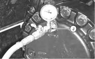
59. Remove plug (4) (not shown). Attach Tooling (J) to cover (2). Reduce the air pressure at the source to 103 kPa (15 psi). Apply air pressure to Tooling (J). This air will test the Duo-Cone seals.
60. Use the ball valve on Tooling (J) to eliminate the air pressure to the final drive. A pressure of 98 kPa (14.2 psi) must be maintained for 30 seconds.
61. Remove Tooling (J). Install plug (6). Torque plug (6) to 80 ± 10 N·m (59 ± 7 lb ft).
62. Remove the final drive from Tooling (A). The weight of the final drive assembly is approximately 310 kg (683 lb).
End By:
a. If necessary, install the final drive sprocket. Refer to Disassembly and Assembly, "Final Drive Sprocket - Remove and Install".
b. Install the final drive. Refer to Disassembly and Assembly, "Final Drive - Install".
Copyright 1993 - 2020 Caterpillar Inc. All Rights Reserved. Private Network For SIS Licensees.
Illustration 38 g00783362Shutdown SIS
Previous Screen
Product: EXCAVATOR
Model: 330D LN EXCAVATOR GGE
Configuration: 330D L & 330D N Hydraulic Excavator GGE00001-UP (MACHINE) POWERED BY C-9 Engine
Disassembly and Assembly
330D, 336D, 336D2, 340D and 340D2 Excavators and 336D MHPU Mobile Hydraulic Power Unit Machine Systems
Final Drive - Assemble - Type-Two
SMCS - 4050-016
S/N - B6H568-UP
S/N - DTS1-UP
S/N - EAH1-UP
S/N - EDX1-UP
S/N - EFT1-UP
S/N - ERN275-UP
S/N - FAR1-UP
S/N - FFK1-UP
S/N - GGE1-UP
S/N - GGH1-UP
S/N - HHK1-UP
S/N - J2F1-UP
S/N - JBT1-UP
S/N - JLP299-UP
S/N - JTN1-UP
S/N - JWR1-UP
S/N - KDJ1-UP
S/N - LMG1-UP
S/N - LRM1-UP
S/N - M3M1-UP
S/N - M3N1-UP
S/N - M4T1-UP
S/N - MDS1-UP
S/N - MEY179-UP
S/N - MPL1-UP
S/N - MWP1-UP
S/N - MYG1-UP
S/N - MYP1-UP
S/N - NBD169-UP
S/N - NBN1-UP
S/N - PGW1-UP
S/N - PPN1-UP
S/N - PRF1-UP
S/N - PTB1-UP
S/N - RAS573-UP
S/N - T2Y226-UP
S/N - THJ1-UP
S/N - TLY1-UP
S/N - W3K1-UP
S/N - WDC1-UP
S/N - WET1-UP
S/N - WRK1-UP
S/N - XBH1-UP
S/N - YCF1-UP
S/N - ZCT1-UP
S/N - ZML1-UP
Assembly Procedure
1. Make sure that all parts of the final drive are thoroughly clean and free of dirt and debris prior to assembly. Check the condition of all O-ring seals that are used in the final drive. If any of the seals are damaged, use new parts for replacement.
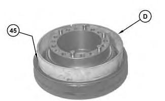
Illustration 1 g03873123
2. Use Tooling (D) to install Duo-Cone seal (45) .
Illustration 2 g03873131
3. Apply Tooling (F) to the surface of dowels (46) . Install dowels (46) .
4. Raise the temperature of lower bearing cone (47) . Install lower bearing cone (47) on motor housing (48) .
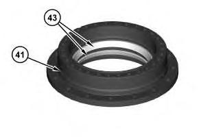
Illustration 3 g03873115
5. Lower the temperature of bearing cups (43) . Install bearing cups (43) in sprocket housing (41) .

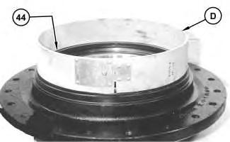
6. Use Tooling (D) to install Duo-Cone seal (44) .
7. Attach Tooling (B) and a suitable lifting device to sprocket housing (41) . The weight of sprocket housing (41) is approximately 110 kg (243 lb). Install sprocket housing (41) .
8. Raise the temperature of upper bearing cone (42) . Install upper bearing cone (42) .
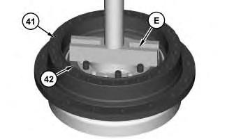
 Illustration 4
g03873145
Illustration 5
g03873151
Illustration 4
g03873145
Illustration 5
g03873151
9. Use Tooling (E) and a suitable press in order to apply force to upper bearing cone (42) . Apply a force of 4000 kg (8818 lb) to the top of Tooling (E) . Rotate sprocket housing (41) in order to seat the roller bearings.
10. Reduce the force on top of Tooling (E) to 3000 ± 300 kg (6614 ± 661 lb). Use Tooling (K) in order to measure Dimension (X) . Record Dimension (X) .

Suggest:
If the above button click is invalid.
Please download this document first, and then click the above link to download the complete manual.
Thank you so much for reading

11. Remove Tooling (E) .
12. Use Tooling (K) in order to measure Dimension (W) on coupling gear (39) . Record Dimension (W) .
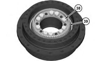
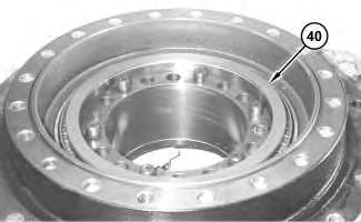
 Illustration 8 g03873199
Illustration 9
g03873204
Illustration 10
g03873207
Illustration 8 g03873199
Illustration 9
g03873204
Illustration 10
g03873207