Service
Previous Screen
Product: EXCAVATOR
Model: 330C MH EXCAVATOR D3C
Configuration: 330C Hydraulic Material Handler D3C00001-UP (MACHINE) POWERED BY C-9 Engine
Disassembly and Assembly
330C Excavator Machine Systems
Travel Motor - Disassemble
SMCS - 4351-015
Disassembly Procedure
A. Remove the travel motor. Refer to Disassembly and Assembly, "Travel Motor - Remove".
Care must be taken to ensure that fluids are contained during performance of inspection, maintenance, testing, adjusting and repair of the product. Be prepared to collect the fluid with suitable containers before opening any compartment or disassembling any component containing fluids.
Refer to Special Publication, NENG2500, "Caterpillar Dealer Service Tool Catalog" for tools and supplies suitable to collect and contain fluids on Caterpillar products.
Dispose of all fluids according to local regulations and mandates.
1. Thoroughly clean the outside of the travel motor prior to disassembly.
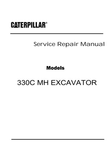
2. Fasten the travel motor in Tooling (A) in a vertical position. The weight of the travel motor is approximately 60 kg (132 lb).
3. Put an alignment mark across the head and the body of the travel motor for assembly purposes. The head must be reinstalled in the head's original position on the body of the travel motor.
Illustration 1
g00887295
Note: During the removal of head (2) from the travel motor, be careful not to damage the mating surfaces of the components.
Spring force can cause personal injury or death.
Do not repair until you have read the Operation and Maintenance Manual.
4. Remove bolts (1) .
5. Remove head (2) from the body of the travel motor.
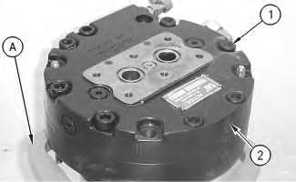
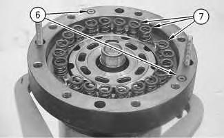
6. Remove O-ring seal (3) , port plate (4) , and bearing (5) .
7. Remove O-ring seals (6) . Remove springs (7) .
 Illustration 2 g00887302
Illustration 3 g00887311
Illustration 2 g00887302
Illustration 3 g00887311
This is an example of the use of Tooling (B) .
g00890074
8. Place a shop towel over brake piston (8) . Retain brake piston (8) with Tooling (B) . Apply approximately 525 kPa (75 psi) of shop air pressure to brake release Port (Y) . Make sure that the shop air pressure is free of water. Brake piston (8) will move up the piston guide, and out of the piston guide. Remove brake piston (8) from the body of the travel motor.
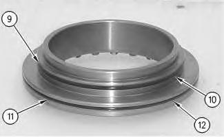

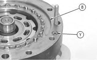 Illustration 4
g00887331
Illustration 5
Illustration 4
g00887331
Illustration 5
9. Remove seal (9) and backup ring (10) from the brake piston.
10. Remove seal (11) and backup ring (12) from the brake piston.
11. Remove plates (13) and friction discs (14) .
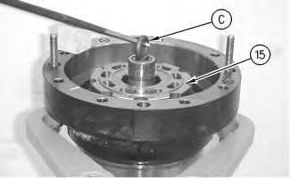
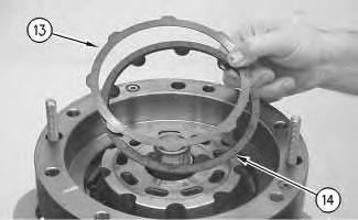 Illustration 6
g00887336
Illustration 7
g00887355
Illustration 8 g00887401
Illustration 6
g00887336
Illustration 7
g00887355
Illustration 8 g00887401
Illustration 9
g00887405
12. Install Tooling (C) into shaft (15) . Use a prybar to remove the rotating assembly (16) from the housing.
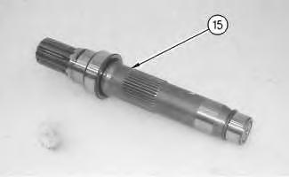
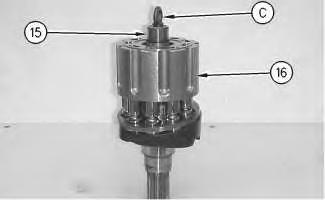
13. Remove Tooling (C) from shaft (15) .
Illustration 10
g00887424
14. Remove shaft (15) from rotating assembly (16) .
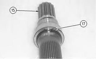
Illustration 11
g00887426
15. Use Tooling (D) in order to remove retaining ring (17) from shaft (15) .
Illustration 12
g00887445
16. Install shaft (15) into a suitable press. Remove bearing race (18) from the shaft.
Illustration 13
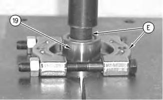
17. Rotate shaft (15) . Install shaft (15) into a suitable press. Install Tooling (E) . Remove bearing race (19) from shaft (15) .
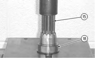 g00887463
Illustration 14 g00887501
18. Remove cam plate (20) from barrel assembly (21) .
Illustration 15 g00887520
19. Remove piston assemblies and retainer plate (22) from barrel assembly (21) .
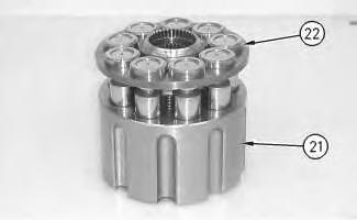
Note: Place marks on the pistons and the barrel assembly. The pistons must be returned to the original position.
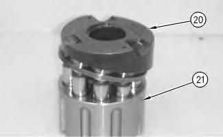
Illustration 16
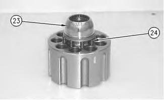
20. Remove ball (23) and springs (24) .
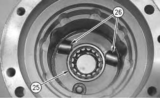
Illustration 17 g00887578
21. Remove bearing (25) .
22. Remove keys (26) and locating pins (not shown) from the body of the travel motor.
Illustration 18
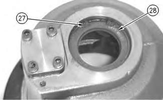
23. Rotate the housing. Use Tooling (F) in order to remove retaining ring (27) .
24. Remove seal (28) .
 g00887558
g00887589
g00887558
g00887589
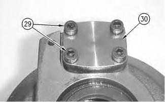
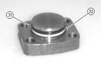
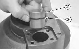 Illustration 19 g00887619
25. Remove bolts (29) and cover (30) .
Illustration 20 g00887729
26. Remove seal (31) and backup ring (32) .
Illustration 21 g00887754
27. Remove piston actuator (33) and seal (34) .
Illustration 19 g00887619
25. Remove bolts (29) and cover (30) .
Illustration 20 g00887729
26. Remove seal (31) and backup ring (32) .
Illustration 21 g00887754
27. Remove piston actuator (33) and seal (34) .
Previous Screen
Product: EXCAVATOR
Model: 330C MH EXCAVATOR D3C
Configuration: 330C Hydraulic Material Handler D3C00001-UP (MACHINE) POWERED BY C-9 Engine
Disassembly and Assembly
330C
Travel Motor - Assemble
SMCS - 4351-016
Assembly Procedure
Required Tools
Note: Replace all O-ring seals and gaskets. Apply a light film of"10W" oil to all components before assembly.
Note: Cleanliness is an important factor. Before assembly, all parts should be thoroughly cleaned in cleaning fluid. Allow the parts to air dry. Wiping cloths or rags should not be used to dry parts. Lint may be deposited on the parts which may cause trouble later. Inspect all parts. If any parts are worn or damaged, use new parts for replacement. All disassembly and all assembly procedures
must be performed on a clean work surface and in a clean hydraulic area. Keep cleaned parts covered and protected at all times.
Illustration 1
g00887762
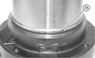
1. Install O-ring seal (35) onto the housing of the travel motor.
Illustration 2
g00887754
2. Install seal (34) and piston actuator (33) .
Illustration 3 g00887729
3. Install backup ring (32) and seal (31) .
Illustration 4 g00887619
4. Install cover (30) and bolts (29) . Tighten bolts (29) to a torque of 28 ± 7 N·m (21 ± 5 lb ft).
Illustration 5 g00887589
5. Apply Tooling (G) to the mating surface of seal (28) . Use Tooling (E) in order to install seal (28) .
6. Use Tooling (F) in order to install retaining ring (27) .
7. Rotate the housing.
8. Install keys (26) and locating pins (not shown) into the body of the travel motor.
9. Install bearing (25) .
Improper assembly of parts that are spring loaded can cause bodily injury.
To prevent possible injury, follow the established assembly procedure and wear protective equipment.
Illustration 6 g00887578 Illustration 7 g0088755810. Install springs (24) into the barrel. Install ball (23) onto springs (24) .
11. Install piston assemblies and retainer plate (22) into barrel assembly (21) .
Note: Take note of the mark on the piston assembly and the barrel assembly. The pistons must be returned to the same position.
12.
Illustration 8 g00887520 Illustration 9 g00887501 Install cam plate (20) onto barrel assembly (21) .Illustration 10
g00888697
13. Install shaft (15) into a suitable press. Install bearing race (19) onto shaft (15) .
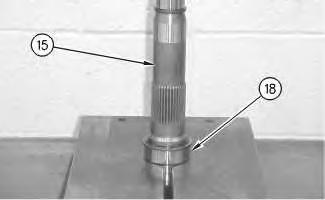
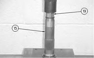
Illustration 11
g00887426
14. Rotate shaft (15) in the suitable press. Use Tooling (D) to install retaining ring (17) onto shaft (15) .
Illustration 12
g00888710
15. Install bearing race (18) onto shaft (15) .
Note: Bearing race (18) must contact retaining ring (17) .
Illustration 13
g00887405
16. Install Tooling (C) into shaft (15) . Install shaft (15) into rotating assembly (16) .
17. Place the pump housing into Tooling (A) .
Illustration 14
g00887401
18. Use Tooling (C) in order to install rotating assembly (16) into the housing.
Illustration 15
g00887501
Illustration 16 g00887578
19. The notches in cam plate (20) must align with keys (26) . The keys are located in the bottom of the housing of the travel motor.
Illustration 17
g00887355
20. Install plates (13) and friction discs (14) into the housing.
Note: Install the plates and the discs alternately.
21. Install backup ring (12) and seal (11) onto the brake piston.
22. Install backup ring (10) and seal (9) onto the brake piston.
23. Rotate brake piston (8) .
24. Install brake piston (8) into the housing.
Note: Brake piston (8) must be level upon installation. The brake piston must be level in order to prevent damage to the O-ring seals.
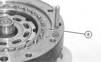 Illustration 18
g00887336
Illustration 19
g00888967
Illustration 20
g00887311
25. Install springs (7) and O-ring seals (6) .
Illustration 21
g00887302
26. Install O-ring seal (3) , port plate (4) , and bearing (5) .
Illustration 22
g00887295
27. Install head (2) onto the body of the travel motor.
Illustration 18
g00887336
Illustration 19
g00888967
Illustration 20
g00887311
25. Install springs (7) and O-ring seals (6) .
Illustration 21
g00887302
26. Install O-ring seal (3) , port plate (4) , and bearing (5) .
Illustration 22
g00887295
27. Install head (2) onto the body of the travel motor.
Note: During the installation of head (2) onto the travel motor, be careful not to damage the mating surfaces of the components.
28. Install bolts (1) . Tighten bolts (1) to a torque of 240 ± 40 N·m (177 ± 30 lb ft).
End By: Install the travel motor. Refer to Disassembly and Assembly, "Travel Motor - Install".
Shutdown SIS
Previous Screen
Product: EXCAVATOR
Model: 330C MH EXCAVATOR D3C
Configuration: 330C Hydraulic Material Handler D3C00001-UP (MACHINE) POWERED BY C-9 Engine
Disassembly and Assembly
330C Excavator Machine Systems Media
Travel Motor - Install
SMCS - 4351-012
Installation Procedure Table 1 Required Tools
Tool Part Number Part Description Qty A Threaded Rod 2
NOTICE
Care must be taken to ensure that fluids are contained during performance of inspection, maintenance, testing, adjusting and repair of the product. Be prepared to collect the fluid with suitable containers before opening any compartment or disassembling any component containing fluids.
Refer to Special Publication, NENG2500, "Caterpillar Dealer Service Tool Catalog" for tools and supplies suitable to collect and contain fluids on Caterpillar products.
Dispose of all fluids according to local regulations and mandates.
1.
Suggest:
If the above button click is invalid.
Please download this document first, and then click the above link to download the complete manual.
Thank you so much for reading

2. Install new O-ring seal (5) . Apply clean hydraulic oil on the O-ring seal.
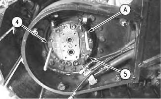
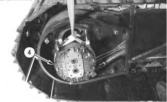
3. Fasten a suitable lifting device to travel motor (4) , as shown. The weight of travel motor (4) is approximately 57 kg (125 lb).
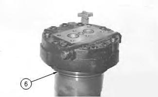 Illustration 1
g00878123
Illustration 2
g00707267
Illustration 3
g00878121
Illustration 1
g00878123
Illustration 2
g00707267
Illustration 3
g00878121