Previous Screen
Product: EXCAVATOR
Model: 330C L EXCAVATOR CAP Configuration: 330C L & 330C LN Excavators CAP00001-UP (MACHINE) POWERED BY C-9 Engine
Disassembly and Assembly 330C Excavator Machine Systems
Final Drive - Disassemble
SMCS - 4050-015
Disassembly Procedure Table 1
Required Tools
Start By:
A. Remove the final drive. Refer to Disassembly and Assembly, "Final Drive - Remove".
Note: Cleanliness is an important factor. Before the disassembly procedure, the exterior of the component should be thoroughly cleaned. This will prevent dirt from entering the internal mechanism.
1. Put an alignment mark across the sections of the final drive for assembly purposes. The parts must be reinstalled in the part's original locations.
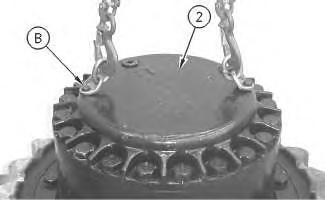
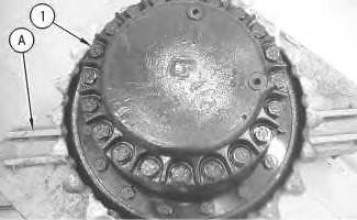
2. Use Tooling (H) and a suitable lifting device to position the final drive on Tooling (A). The combined weight of the final drive assembly is approximately 550 kg (1200 lb).
3. Remove bolts (1) .
4. Use Tooling (B) and a suitable lifting device to remove cover (2). The weight of cover (2) is approximately 32 kg (70 lb).
Illustration 3
5. Remove bolts (3) and gear (4). Check plate (6). Replace plate (6) if plate (6) is worn. Remove plugs (5) from cover (2) .
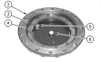
Illustration 4
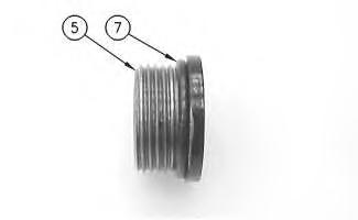
6. Remove O-ring seals (7) from plugs (5) .
 g00892888
g00892906
7. Remove gear (8) and spacer (9) .
8. Use Tooling (C) to remove retaining ring (10). Remove washer (11) and gear (12). Remove bearing assembly (13) and washer (14) .
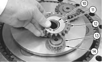
9. Repeat Step 8 for the other two gear assemblies.
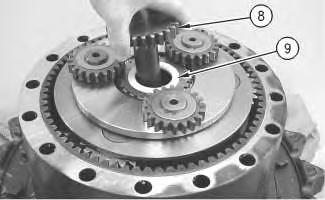 Illustration 5
g00892930
Illustration 6
g00892965
Illustration 7
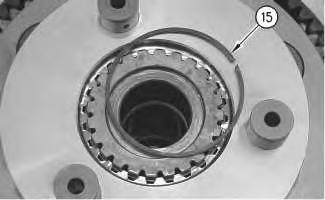
10. Remove retaining ring (15) .
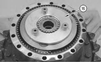
11. Remove carrier assembly (16) .
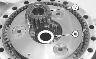
12. Remove gear (17) and spacer (18) .
 g00892968
Illustration 8
g00892975
Illustration 9
g00892977
13. Use Tooling (D) and a suitable lifting device to remove planetary carrier (19). The weight of planetary carrier (19) is approximately 48 kg (105 lb).
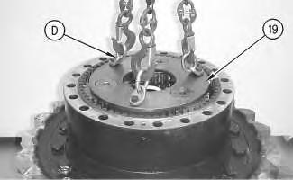
14. Remove retainer ring (21). Lift planetary carrier (19) off sun gear (20) .
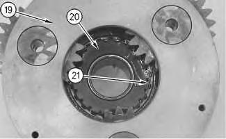 Illustration 10 g00892997
Illustration 11 g00893019
Illustration 12
g00896860
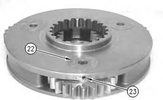
15. Drive spring pin (23) into planetary shaft (22) .
Illustration 13
g00893043
16. Remove planetary shaft (22). Use a suitable punch to remove spring pin (23) from planetary shaft (22) .
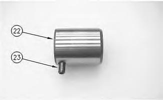
Illustration 14
g00896863
17. Remove washers (24) and bearing (25) from planetary gear (26) .
18. Repeat Steps 15 through 17 for the other two planetary gears.
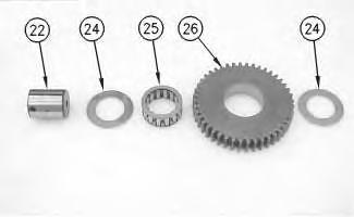
Illustration 15
19. Remove spacer (27) .
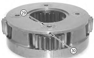
20. Use two people to remove carrier assembly (28). The weight of carrier assembly (28) is approximately 38 kg (85 lb).
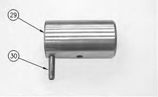
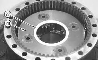
Illustration 16
21. Drive spring pin (30) into shaft (29) .
g00897431 g00893652Illustration 17
g00893658
22. Remove shaft (29). Use a suitable punch to remove spring pin (30) from shaft (29) .
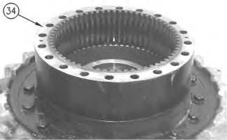
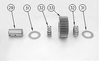
Illustration 18 g00893674
23. Remove washers (31) and bearings (32) from planetary gear (33) .
24. Repeat Steps 21 through 23 for the other three planetary gears.
Illustration 19 g00893683
25. Use two people to remove gear (34). The weight of gear (34) is approximately 41 kg (90 lb).
Illustration 20
26. Remove O-ring seal (35) .
Illustration 21
27. Remove bolt (36A) and plate (36B) from both sides of stopper plate (36) .
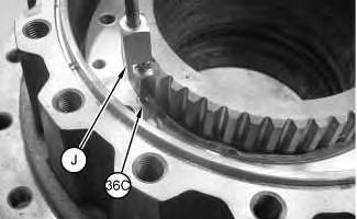
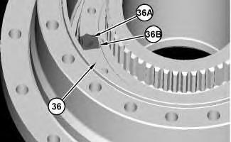
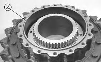
Illustration 22
Typical example
28. Use Tooling (J) to remove dowels (36C) .
Illustration 23
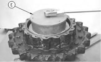
29. Secure the spanner socket from Tooling (E) to stopper plate (36). Use Tooling (E) to remove stopper plate (36) .
Illustration 24
30. Use Tooling (F) and a suitable lifting device to remove sprocket housing (38) from housing (37). The weight of sprocket housing (38) is approximately 385 kg (850 lb).
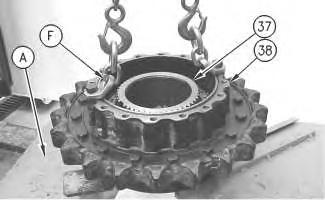
 g00893837
g00893850
31. Remove Duo-Cone seal (39) from housing (37) .
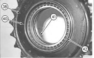
32. Rotate sprocket housing (38) .
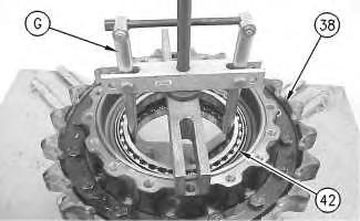
33. Remove Duo-Cone seal (40) .
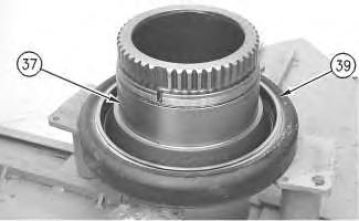 Illustration 25
g00893858
Illustration 26
g00893865
Illustration 27
g00893872
34. Use Tooling (G) in order to remove bearings (41) and (42) from sprocket housing (38) .
35. If necessary, remove the final drive sprocket from the sprocket housing. Refer to Disassembly and Assembly, "Final Drive Sprocket - Remove and Install".
Previous Screen
Product: EXCAVATOR
Model: 330C L EXCAVATOR CAP Configuration: 330C L & 330C LN
Disassembly and Assembly
CAP00001-UP (MACHINE) POWERED BY C-9 Engine
330C Excavator Machine Systems
Final Drive - Assemble
SMCS - 4050-016
Assembly Procedure
Required Tools
S 1U-8846 Gasket Sealant 1
T FT-2770 Leak Down Test Tool 1
Note: Cleanliness is an important factor. Before assembly, all parts should be thoroughly cleaned in cleaning fluid. Allow the parts to air dry. Wiping cloths or rags should not be used to dry parts. Lint may be deposited on the parts which may cause later trouble. Inspect all parts. If any parts are worn or damaged, use new parts for replacement. All disassembly and all assembly procedures must be performed on a clean work surface and in a clean hydraulic area. Keep cleaned parts covered and protected at all times.
Note: O-rings, gaskets, and seals should always be replaced. A used O-ring may not have the same sealing properties as a new O-ring. Use Tooling (L) during the assembly procedure.
Note: Some of the images that are in this procedure do not show the sprocket assembly that is attached to the final drive housing. If necessary, the weights that are given include the weight of the sprocket assembly.
Note: Apply a light film of hydraulic oil to all components before assembly.
1. Install the final drive sprocket if the sprocket was removed from the main housing. Refer to Disassembly and Assembly, "Final Drive Sprocket - Remove and Install".
Illustration 1
g00893865
2. Apply Tooling (M) to the outer diameter of bearings (41) and (42) .
3. Use a suitable press to install bearings (41) and (42) in the original locations in sprocket housing (38) .
4. Make sure that bearings (41) and (42) contact the counterbore in sprocket housing (38) .
5. Use Tooling (K) to install Duo-Cone seal (40) .

7.
Tooling (F) and a suitable lifting device to position sprocket housing (38) on housing (37) . The weight of sprocket housing (38) is approximately 295 kg (650 lb).


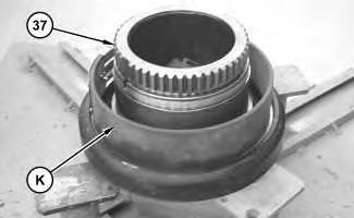 Illustration 2 g01151065
Illustration 3 g00893858
6. Use Tooling (K) to install Duo-Cone seal (39) .
Illustration 4 g00893850
Use
8. Remove Tooling (F) from sprocket housing (38) .
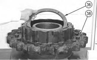
Note: A new stopper plate (36) should be used.
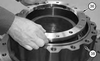
9. Install stopper plate (36) . Do not tighten stopper plate (36) at this time.
Note: Stopper plate (36) will secure housing (37) to sprocket housing (38) .
10. Use Tooling (F) and a suitable lifting device to position housing (37) and sprocket housing (38) into a suitable press. The combined weight of housing (37) and sprocket housing (38) is approximately 385 kg (850 lb).
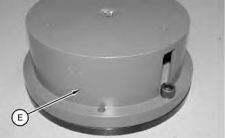
11. Remove stopper plate (36) .
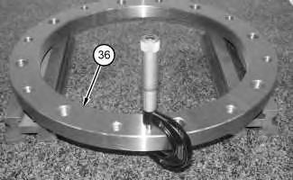
12. Assemble Tooling (E) , as shown.
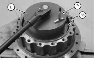
Illustration 5 g00894301 Illustration 6 g0115099213. Install Tooling (E) into sprocket housing (38) , as shown.
14. Apply a force of 4000 kg (8820 lb) to the top of Tooling (E) . Rotate sprocket housing (38) in order to seat the bearings.
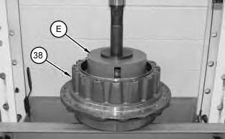
15. Reduce the force on the top of Tooling (E) to 3000 kg (6600 lb).
16. Use Tooling (P) to take a measurement in three locations. Average the three measurements and record this figure as Dimension (W) .
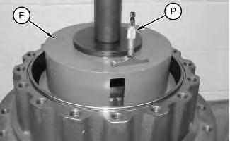 Illustration 7
g01150993
Illustration 8
g01150994
Illustration 9 g01150996
17. Remove Tooling (E) .
18. Separate Tooling (E) .
19. Use a micrometer in order to measure the thickness at three locations of the spacer from Tooling (E) . Record the average measurement as Dimension (X) .
Illustration 10 g01150997
20. Use a micrometer in order to measure the thickness at three locations of stopper plate (36) . Record the average measurement as Dimension (Y) .
21. Subtract Dimension (X) from Dimension (Y) and record this figure as Dimension (Z) .
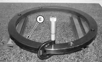
Illustration 11
g01151019
22. Install stopper plate (36) onto housing (37) . Do not tighten the stopper plate at this time. Note: Stopper plate (36) will secure the final drive assembly while the final drive assembly is repositioned onto Tooling (A) .
23. Use Tooling (F) and a suitable lifting device to reposition the final drive assembly onto Tooling (A) . The combined weight of housing (37) and sprocket housing (38) is approximately 385 kg (850 lb).
24. Secure the final drive assembly to Tooling (A) .
Illustration 12
g01150998
25. Secure the spanner socket from Tooling (E) to stopper plate (36) .
26. In order to determine the final bearing preload, add Dimension (W) to Dimension (Z) and record this figure as Dimension (V) .
27. Use Tooling (P) to measure the distance in three locations.
28. Tighten stopper plate (36) until the average of the measurements is equal to Dimension (V) .
29. Remove Tooling (E) .
Illustration 13 g01150999
Typical Example
30. Align Tooling (Q) in the notch on stopper plate (36) . Secure Tooling (Q) to stopper plate (36) and fasten a suitable vacuum to Tooling (Q) .
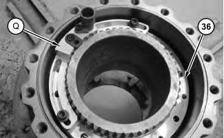
Illustration 14 g01151000
Typical Example
31. Use a suitable drill and Tooling (Q) in order to drill a hole to the depth of 15 mm (0.6 inch) in stopper plate (36) and housing (37) .
32. Remove Tooling (Q) .
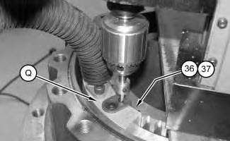
Illustration 15 g01151054
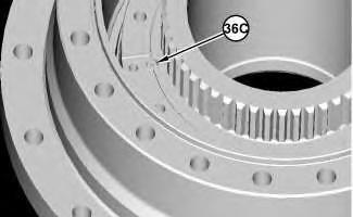
33. Install dowel (36C) .
Illustration 16
g01150936
34. Apply Tooling (R) to bolt (36A) . Install plate (36B) and bolt (36A) into stopper plate (36) .


35. Repeat Steps 30 through 34 for the other side of stopper plate (36) .
Illustration 17 g00893694
36. Install O-ring seal (35) .
37. Use two people to install gear (34) . The weight of gear (34) is approximately 41 kg (90 lb).

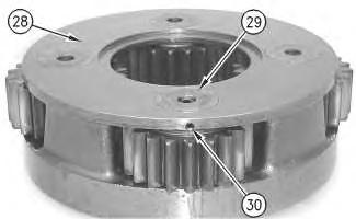

Illustration 19
38. Assemble carrier assembly (28) , as follows.
Illustration 18 g00893683 g00894968Illustration 20
g00893674
a. Install bearings (32) in planetary gear (33) .
b. Install thrust washers (31) and planetary gear (33) in the carrier assembly.
c. Use a deburring tool in order to remove the metal burr from the openings in the carrier. Install planetary shaft (29) in the carrier assembly.
d. Drive spring pin (30) into planetary shaft (29) .
g00941047
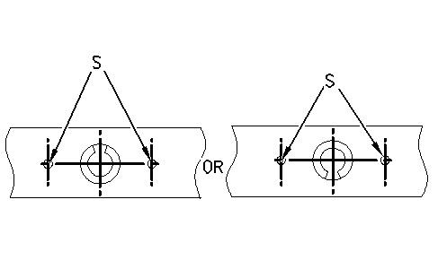
The stake mark is at position (S) .
e. Orient the split in spring pin (30) vertically to the carrier. Align the split in the spring pin to the top or to the bottom. Make a stake mark on each side of the spring pin hole in the carrier. Each stake mark should be approximately 1.5 mm (0.06 inch) from the outside diameter of the spring pin hole.
39. Repeat Steps 38.a through 38.e in order to install the remaining two planetary gears in the carrier assembly.
Illustration 21Suggest:
If the above button click is invalid.
Please download this document first, and then click the above link to download the complete manual.
Thank you so much for reading

40. Use two people to install carrier assembly (28) . The weight of carrier assembly (28) is approximately 38 kg (85 lb).


41. Install spacer (27) .
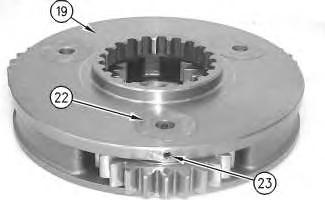
42. Assemble planetary carrier (19) , as follows.
Illustration 22 g00897431 Illustration 23 g00897548 Illustration 24 g00896863