Shutdown SIS
Previous Screen
Product: EXCAVATOR
Model: 329E LN EXCAVATOR RLD
Configuration: 329E L & 329E LN Excavators RLD00001-UP (MACHINE) POWERED BY C7.1 Engine
Disassembly and Assembly
324E and 329E Excavators and 329E MHPU Mobile Hydraulic Power Unit Machine Systems Media
Travel Motor - Disassemble
SMCS - 4351-015
S/N - JCZ1-UP
S/N - K2L1-UP
S/N - KTE1-UP
S/N - LDG1-UP
S/N - PNW1-UP
S/N - PTY1-UP
S/N - RDX1-UP
S/N - RLD1-UP
S/N - TLF1-UP
S/N - TST1-UP
S/N - WJK1-UP
S/N - ZCD1-UP
Disassembly Procedure
Table 1
Required Tools
Tool Part Number Part Description
F
Start By:
A. Remove the travel motor. Refer to Disassembly and Assembly, "Travel Motor - Remove".
NOTICE
Care must be taken to ensure that fluids are contained during performance of inspection, maintenance, testing, adjusting, and repair of the product. Be prepared to collect the fluid with suitable containers before opening any compartment or disassembling any component containing fluids.
Refer to Special Publication, NENG2500, "Dealer Service Tool Catalog" for tools and supplies suitable to collect and contain fluids on Cat products.
Dispose of all fluids according to local regulations and mandates.
1. Thoroughly clean the outside of the travel motor prior to disassembly.
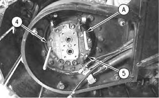
2. Fasten the travel motor in Tooling (A) in a vertical position. The weight of the travel motor is approximately 60 kg (132 lb).
3. Put an alignment mark across the head and the body of the travel motor for assembly purposes. The head must be reinstalled in the head's original position on the body of the travel motor.
Note: During the removal of head (2) from the travel motor, be careful not to damage the mating surfaces of the components.
Spring force can cause personal injury or death.
Do not repair until you have read the Operation and Maintenance Manual.
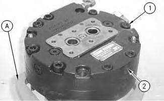
4. Remove bolts (1) .
5. Remove head (2) from the body of the travel motor.
6. Remove O-ring seal (3), port plate (4), and bearing (5) .
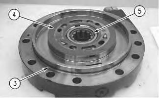 Illustration 1
g00887295
Illustration 2
g00887302
Illustration 1
g00887295
Illustration 2
g00887302
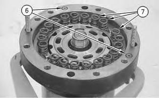
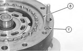
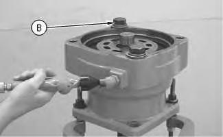 Illustration 3
g00887311
7. Remove O-ring seals (6). Remove springs (7) .
Illustration 4
g00887331
Illustration 5
g00890074
This is an example of the use of Tooling (B) .
Illustration 3
g00887311
7. Remove O-ring seals (6). Remove springs (7) .
Illustration 4
g00887331
Illustration 5
g00890074
This is an example of the use of Tooling (B) .
8. Place a shop towel over brake piston (8). Retain brake piston (8) with Tooling (B). Apply approximately 525 kPa (75 psi) of shop air pressure to brake release Port (Y). Make sure that the shop air pressure is free of water. Brake piston (8) will move up the piston guide, and out of the piston guide. Remove brake piston (8) from the body of the travel motor.
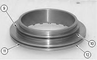
9. Remove seal (9) and backup ring (10) from the brake piston.
10. Remove seal (11) and backup ring (12) from the brake piston.
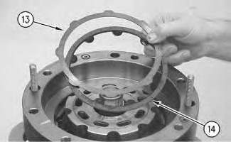
Illustration 6 g00887336 Illustration 7 g00887355 11. Remove plates (13) and friction discs (14) .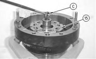
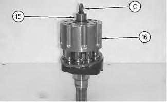
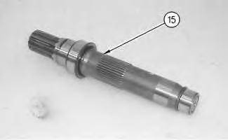 Illustration 8
g00887401
Illustration 9
g00887405
12. Install Tooling (C) into shaft (15). Use a prybar to remove the rotating assembly (16) from the housing.
13. Remove Tooling (C) from shaft (15) .
Illustration 10
g00887424
Illustration 8
g00887401
Illustration 9
g00887405
12. Install Tooling (C) into shaft (15). Use a prybar to remove the rotating assembly (16) from the housing.
13. Remove Tooling (C) from shaft (15) .
Illustration 10
g00887424
14. Remove shaft (15) from rotating assembly (16) .
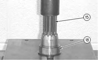
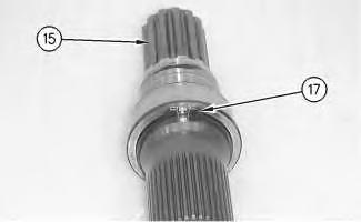
Illustration 11
g00887426
15. Use Tooling (D) in order to remove retaining ring (17) from shaft (15) .
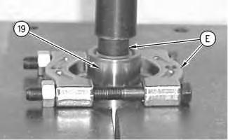
Illustration 12
g00887445
16. Install shaft (15) into a suitable press. Remove bearing race (18) from the shaft.
Illustration 13
g00887463
17. Rotate shaft (15). Install shaft (15) into a suitable press. Install Tooling (E). Remove bearing race (19) from shaft (15) .
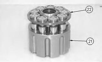
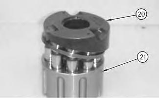
Illustration 14
g00887501
18. Remove cam plate (20) from barrel assembly (21) .
Illustration 15
g00887520
19. Remove piston assemblies and retainer plate (22) from barrel assembly (21) .
Note: Place marks on the pistons and the barrel assembly. The pistons must be returned to the original position.
Illustration 16 g00887558
20. Remove ball (23) and springs (24) .
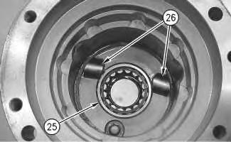
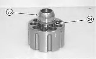
Illustration 17 g00887578
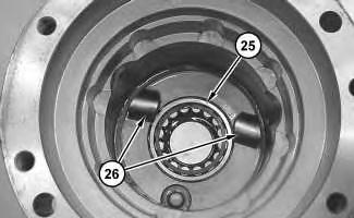
21. Remove bearing (25) .
22. Remove keys (26) and locating pins (not shown) from the body of the travel motor.
Illustration 18
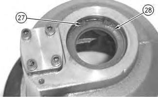
g0088758923. Rotate the housing. Use Tooling (F) in order to remove retaining ring (27) .
24. Remove seal (28) .
Illustration 19
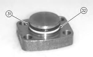
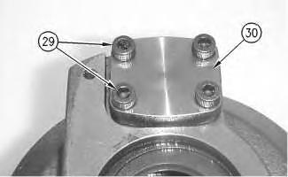
25. Remove bolts (29) and cover (30) .
Illustration 20
26. Remove seal (31) and backup ring (32) .
g00887619 g00887729Illustration 21
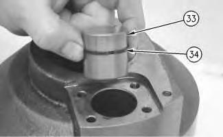
27. Remove piston actuator (33) and seal (34).
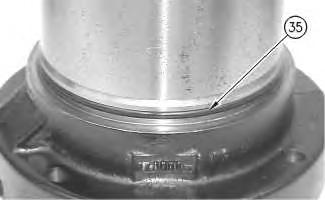
Illustration 22
28. Remove O-ring seal (35) from the housing of the travel motor. Copyright 1993 - 2020 Caterpillar Inc.
Shutdown SIS
Previous Screen
Product: EXCAVATOR
Model: 329E LN EXCAVATOR RLD
Configuration: 329E L & 329E LN Excavators RLD00001-UP (MACHINE) POWERED BY C7.1 Engine
Disassembly and Assembly
324E and 329E Excavators and 329E MHPU Mobile Hydraulic Power Unit Machine Systems Media
Travel Motor - Assemble
SMCS - 4351-016
Assembly Procedure
Illustration 1
g00887762
1. Install O-ring seal (35) onto the housing of the travel motor.
Illustration 2
g00887754
2. Install seal (34) and piston actuator (33). Lubricate the surfaces of piston actuator (33) with lubricant that is being sealed.
Illustration 3
g00887729
3. Install backup ring (32) and seal (31) .
4. Install cover (30) and bolts (29). Tighten bolts (29) to a torque of 28 ± 7 N·m (21 ± 5 lb ft).
5. Apply Tooling (G) to the mating surface of lip seal (28). Use Tooling (E) in order to install lip seal (28). Lubricate the sealing lip of lip seal (28) with lubricant that is being sealed.
6. Use Tooling (F) in order to install retaining ring (27) .
Illustration 4 g00887619
Illustration 5 g00887589
g02107975
7. Rotate the housing.
8. Install keys (26) and locating pins (not shown) into the body of the travel motor.
9. Install bearing (25) .
g00887558
Improper assembly of parts that are spring loaded can cause bodily injury.
To prevent possible injury, follow the established assembly procedure and wear protective equipment.
10. Install springs (24) into the barrel assembly. Install ball (23) onto springs (24). Lubricate ball (23) with lubricant that is being sealed.
Illustration 6
Illustration 7
Illustration 8
g00887520
11. Lubricate the piston assemblies with lubricant that is being sealed. Install piston assemblies and retainer plate (22) into barrel assembly (21).
Note: Take note of the mark on the piston assembly and the barrel assembly. The pistons must be returned to the same position.
Illustration 9
g00887501
12. Lubricate cam plate (20) with lubricant that is being sealed. Install cam plate (20) onto barrel assembly (21) .
Illustration 10
g00888697
13. Install shaft (15) into a suitable press. Install bearing race (19) onto shaft (15) .
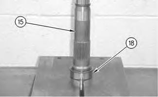
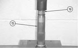
Illustration 11
g00887426
14. Rotate shaft (15) in the suitable press. Use Tooling (D) to install retaining ring (17) onto shaft (15) .
Illustration 12
g00888710
15. Install bearing race (18) onto shaft (15) .
Note: Bearing race (18) must contact retaining ring (17) .
Illustration 13
g00887405
16. Install Tooling (C) into shaft (15). Install shaft (15) into rotating assembly (16) .
17. Place the pump housing into Tooling (A) .
Illustration 14
g02107957
18. Use Tooling (C) in order to install rotating assembly (16) into the housing.
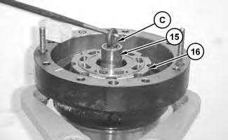 Illustration 15 g00887501
Illustration 16 g02107975
19. The notches in cam plate (20) must align with keys (26). The keys are located in the bottom of the housing of the travel motor.
Illustration 17 g00887355
20. Install plates (13) and friction discs (14) into the housing.
Illustration 15 g00887501
Illustration 16 g02107975
19. The notches in cam plate (20) must align with keys (26). The keys are located in the bottom of the housing of the travel motor.
Illustration 17 g00887355
20. Install plates (13) and friction discs (14) into the housing.
Note: Install the plates and the discs alternately.
21. Install backup ring (12) and seal (11) onto the brake piston.
22. Install backup ring (10) and seal (9) onto the brake piston.
23. Rotate brake piston (8) .
24. Install brake piston (8) into the housing.
Note: Brake piston (8) must be level upon installation. The brake piston must be level in order to prevent damage to the O-ring seals.
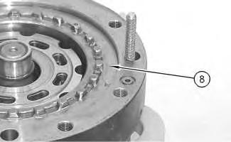 Illustration 18
g00887336
Illustration 19
g00888967
Illustration 18
g00887336
Illustration 19
g00888967
25. Install springs (7) and O-ring seals (6) .
26. Lubricate port plate (4) with lubricant that is being sealed. Install O-ring seal (3), port plate (4), and bearing (5) .
Illustration 20
g00887311
Illustration 21
g00887302
Illustration 22
g00887295
Improper assembly of parts that are spring loaded can cause bodily injury.
To prevent possible injury, follow the established assembly procedure and wear protective equipment.
27. Install head (2) onto the body of the travel motor.
Note: During the installation of head (2) onto the travel motor, be careful not to damage the mating surfaces of the components.
28. Install bolts (1). Tighten bolts (1) to a torque of 177 ± 18 N·m (130.5 ± 13.27 lb ft).
End By: Install the travel motor.
Copyright 1993 - 2020 Caterpillar Inc.
All Rights Reserved.
Private Network For SIS Licensees.
Mon May 4 16:30:32 UTC+0800 2020
Shutdown SIS
Previous Screen
Product: EXCAVATOR
Model: 329E LN EXCAVATOR RLD
Configuration: 329E L & 329E LN Excavators RLD00001-UP (MACHINE) POWERED BY C7.1 Engine
Disassembly and Assembly
324E and 329E Excavators and 329E MHPU Mobile Hydraulic Power Unit Machine Systems Media
Travel Motor - Install
SMCS - 4351-012
Installation Procedure Table 1 Required Tools Tool
A 9U-7692
NOTICE
Care must be taken to ensure that fluids are contained during performance of inspection, maintenance, testing, adjusting, and repair of the product. Be prepared to collect the fluid with suitable containers before opening any compartment or disassembling any component containing fluids.
Refer to Special Publication, NENG2500, "Dealer Service Tool Catalog" for tools and supplies suitable to collect and contain fluids on Cat products.
Dispose of all fluids according to local regulations and mandates.
1. Thoroughly clean the mating surfaces of the travel motor and the final drive.
Illustration 1
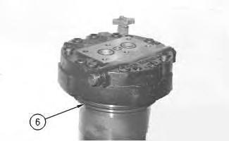
2. Install new O-ring seal (6). Apply clean hydraulic oil on the O-ring seal.
Illustration 2
3. Attach a suitable lifting device to travel motor (4), as shown.
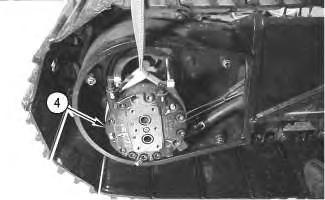
4. The weight of the travel motor is approximately 57 kg (125 lb).
 g00878123
g00707267
Illustration 3
g00878121
g00878123
g00707267
Illustration 3
g00878121
Suggest:
If the above button click is invalid.
Please download this document first, and then click the above link to download the complete manual.
Thank you so much for reading

5. Carefully install travel motor (4) onto Tooling (A). Slide the travel motor into the final drive.
6. Install one of three bolts (5) that secures the travel motor to the final drive.
7. Remove Tooling (A) .
Illustration 4 g00707275
Typical example
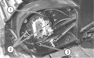
8. Install remaining bolts (2) .
9. Connect hose assembly (3). Connect hose assembly (1) .
10. Fill the final drive with oil.
ReferenceRefer to Operation and Maintenance Manual, "Lubricant Viscosities" for the proper oil viscosity.
ReferenceRefer to Operation and Maintenance Manual, "Final Drive Oil Level - Check" for the correct filling procedure.
11. Install high efficiency filters in place of the pilot filter, the case drain filter, and the return filter.
Note: High efficiency filters should not be run for more than 250 hours before you change back to the standard filters.
12. Obtain a hydraulic oil sample from the main S·O·S port.
ReferenceRefer to Operation and Maintenance Manual, "Sampling Interval and Location of Sampling Valve" for the correct location.
13. If the S·O·S sample exceeds ISO 18/15, flush the hydraulic system.
ReferenceRefer to Contamination Control Guidelines, SEBF8436, "Hydraulic System Flushing Procedure for 322C Hydraulic Excavators" for further information.