Previous Screen
Product: EXCAVATOR
Model: 328D LCR EXCAVATOR RMX
Configuration: 328D LCR Excavator RMX00001-UP (MACHINE) POWERED BY C7 Engine
Disassembly and Assembly
328D Excavator Machine Systems
Swing Drive - Disassemble
SMCS - 5459-015
Disassembly Procedure Table 1
Required Tools
Start By:
a. Remove the swing drive. Refer to Disassembly and Assembly, "Swing Drive - Remove"
NOTICE
Care must be taken to ensure that fluids are contained during performance of inspection, maintenance, testing, adjusting, and repair of the product. Be prepared to collect the fluid with suitable containers before opening any compartment or disassembling any component containing fluids.
Refer to Special Publication, NENG2500, "Dealer Service Tool Catalog" for tools and supplies suitable to collect and contain fluids on Cat® products.
Dispose of all fluids according to local regulations and mandates.
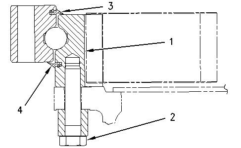
g00518369
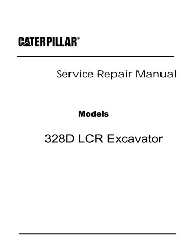
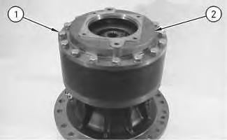
1. Position the swing drive on suitable cribbing, as shown. The weight of the swing drive is approximately 281 kg (620 lb).
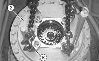
2. Put an alignment mark on the cover and the housing of the swing drive for assembly purposes.
3. Remove bolts (1) and cover (2).
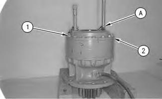
4. Install Tooling (A) to cover (2).
g00518372
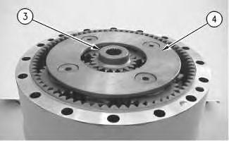
Illustration 1 Illustration 2 5. Use a suitable lifting device and Tooling (A) to remove cover (2) from the ring gear of the swing drive.6. Use two people to remove carrier assembly (3). The weight of the carrier assembly is approximately 23 kg (50 lb).
7. Use the following procedure to disassemble carrier assembly (3).
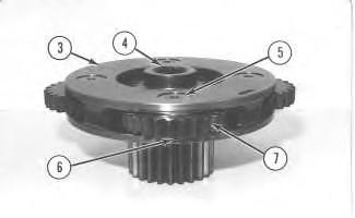

Illustration 5 g00518400
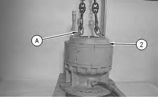
a. Remove sun gear (4) from carrier assembly (3).
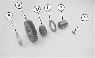
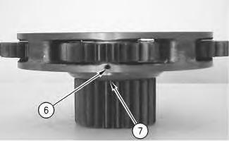
b. Drive spring pin (6) into planetary shaft (5) with a hammer and a punch.
Illustration 3 g00518397 Illustration 4 g00518398c. Remove planetary shaft (5), thrust washers (9), and planetary gear (7) from the carrier assembly.
d. Remove bearing (8) from planetary gear (7).
e. Remove spring pin (6) from planetary shaft (5) with a hammer and a punch.
f. Repeat Steps 7.a through 7.e to remove the other three planetary gears from the carrier assembly.
Illustration 6
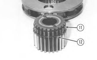
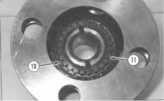
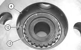
g. Remove retaining ring (10) with a screwdriver. Remove gear (11) from carrier (3).
Illustration 7
h. Remove retaining ring (12) from gear (11).
g00518543 g00518549Illustration 8
g00518551
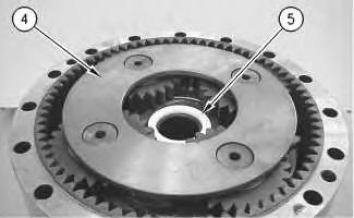
8. Remove retaining ring (15) that holds carrier assembly (13) in position.
9. Remove spacer (14) from carrier assembly (13).
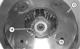
Illustration 9
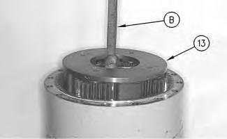
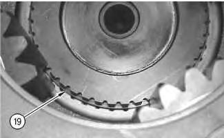
g00518552
10. Slide a piece of steel bar stock between the planetary gears in carrier assembly (13), as shown. Make sure that the steel bar stock is centered in the carrier assembly. Fasten Tooling (B) and a suitable lifting device to the steel bar stock, as shown. Slowly lift carrier assembly (13) from the swing drive housing. The weight of carrier assembly (13) is approximately 39 kg (86 lb).
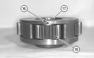
11. Use the following procedure to disassemble carrier assembly (13).
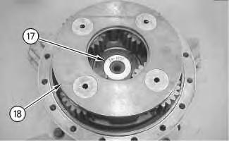
a. Drive spring pin (16) into planetary shaft (17) with a hammer and a punch.
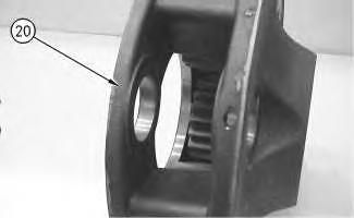
b. Remove planetary shaft (17), thrust washers (20), and planetary gear (18) from the carrier assembly.
c. Remove bearings (19) from planetary gear (18).
d. Remove spring pin (16) from planetary shaft (17) with a hammer and a punch.
e. Repeat Steps 11.a through 11.d to remove the other three planetary gears from the carrier assembly.
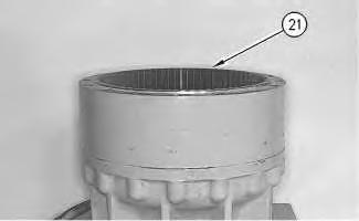
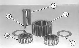 Illustration 10
g00518553
Illustration 11
g00518555
Illustration 12
g00518581
12. Use two people to remove ring gear (21) from the swing drive housing. The weight of the ring gear is approximately 39 kg (86 lb).
Illustration 10
g00518553
Illustration 11
g00518555
Illustration 12
g00518581
12. Use two people to remove ring gear (21) from the swing drive housing. The weight of the ring gear is approximately 39 kg (86 lb).
Illustration 13
13. Use Tooling (C) to remove retaining ring (22).
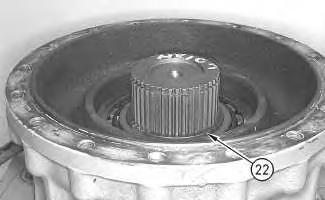
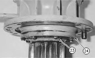
Illustration 14
14. Loosen, but do not remove bolts (23) that secure cage (24) to the swing drive housing.
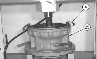
Illustration 15
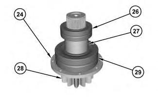
15. Place swing drive housing (25) in a suitable press, as shown. The combined weight of the swing drive housing (25), the pinion shaft (28) and the bearing cage (24) is approximately 136 kg (300 lb).
16. Place suitable cribbing directly under the pinion shaft to prevent pinion shaft (28) from falling when cage (24) is pressed out of the swing drive housing.
17. Remove and discard bolts (23) that secure cage (24) to the swing drive housing. Carefully press cage (24) and pinion shaft (28) as a unit out of swing drive housing (25). Discard pinion shaft (28), cage (24), bearing (29), sleeve (27), and bearing (26) as an assembly.
Previous Screen
Product: EXCAVATOR
Model: 328D LCR EXCAVATOR RMX
Configuration: 328D LCR Excavator RMX00001-UP (MACHINE) POWERED BY C7 Engine
Disassembly and Assembly
328D Excavator Machine Systems
Swing Drive - Assemble
SMCS - 5459-016
Assembly Procedure
Required Tools
Note: Cleanliness is an important factor. Before assembly, all parts should be thoroughly cleaned in cleaning fluid. Allow the parts to air dry. Wiping cloths or rags should not be used to dry parts. Lint may be deposited on the parts which may cause later trouble. Inspect all parts. If any parts are worn or damaged, use new parts for replacement.
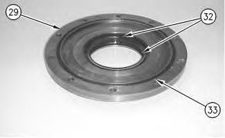
Illustration 1 g00869899
1. Install lip seals (32) and O-ring seal (33) in bearing cage (29).
Illustration 2 g00870134
Note: Lubricate the seals and the seal surface of the shaft before you install the cage assembly.
2. Carefully install cage (29) on shaft (31).
3. Raise the temperature of bearing (36) to 135 °C (275 °F) and use two people to install the bearing on shaft (31). The weight of bearing (36) is approximately 35 kg (77 lb).
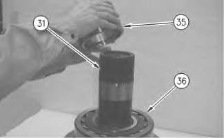
4. Install spacer (35) on shaft assembly (31). Install the spacer with relief against bearing (36).
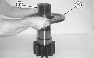 Illustration 3 g00870142
Illustration 4
g00870160
5. Raise the temperature of bearing (34) to 135 °C (275 °F). Install the bearing on shaft (31) and against spacer (35).
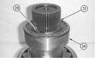
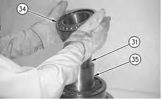
Illustration 5
g00870169
6. Use Tooling (A) to install retaining ring (28) on shaft (31) and against bearing (34).
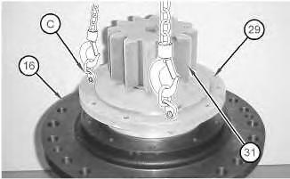
Illustration 6
g01041406
7. Install shaft assembly (31) in swing drive housing (16).
a. Apply 5P-3931 Anti-Seize Compound on the inside diameter of swing drive housing (16).
b. Lower the temperature of shaft assembly (31).
c. Attach Tooling (C) and a suitable lifting device to the shaft assembly.
d. Install the shaft assembly into swing drive housing (16). Bearing (34) must be within the bore of the swing drive housing.
e. Remove Tooling (C) and the suitable lifting device from the shaft assembly. Attach Tooling (C) and the suitable lifting device to the swing drive housing.
f. Lift the swing drive vertically. Use a hammer and a drift to align bearing (34) in the lower bore of the swing drive housing. When the bearing is properly aligned in the bore, shaft assembly (31) will drop into the proper position within the swing drive housing.
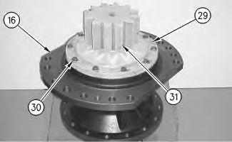
Illustration 7
g00870264
8. Apply 1U-8846 Sealant on the threads of bolts (30).
9. Install bolts (30) and washers in bearing cage (29) and swing drive housing (16).
g00869483
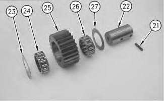 Illustration 8
Illustration 9
10. Install bearings (24) and (26) in gear (25).
g00870281
11. Install gear (25) and washers (23) and (27) in carrier (20).
12. Lower the temperature of shaft (22). Install the shaft in carrier assembly (20).
13. Install pin (21) in the carrier assembly and the shaft.
14. Use a hammer and a center punch to stake the pin in the carrier housing.
15. Repeat Steps 10 through Steps 14 on the remaining gear assemblies.
Illustration 10
g00869464
16. Use a suitable lifting device to install carrier assembly (20). The weight of carrier assembly (20) is approximately 68 kg (150 lb).
Illustration 11
17. Install retaining ring (19).
Illustration 12 g00869406
18. Install spacer (17) in carrier assembly (18).
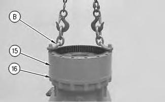
Illustration 13
19. Make sure that the mating surfaces of ring gear (15) and swing drive housing (16) are thoroughly clean.
 g00869460
g00869390
g00869460
g00869390
20. Apply 1U-8846 Gasket Sealant to the face of swing drive housing (16) and the face of ring gear (15).
21. Use Tooling (B) and a suitable lifting device to install ring gear (15) in swing drive housing (16). The weight of ring gear (15) is approximately 80 kg (175 lb).

22. Install retaining ring (14) into the sun gear.
23. Install sun gear (13) in carrier assembly (4). Install upper retaining ring (12).
24. Assemble carrier assembly (4).
Illustration 14 g00869383 Illustration 15 g00869377Illustration 16 g00869315
a. Apply clean SAE 30W oil on bearing (10). Install bearing (10) in planetary gear (9).
b. Install thrust washer (8) on one side of planetary gear (9).
c. Install thrust washer (11) on the other side of planetary gear (9).
d. Use a deburring tool to remove the metal burr from the openings in the carrier.
e. Install planetary gear (9) and the thrust washers in carrier assembly (4).
f. Install planetary shaft (7) through the gear assembly into the carrier assembly. Make sure that the spring pin hole in the planetary shaft is in alignment with the spring pin hole in the carrier.
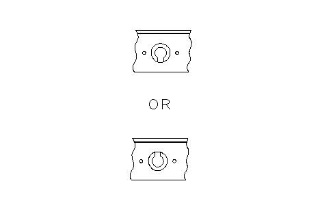
Illustration 17 g00869309 Illustration 18 g00703700g. Drive spring pin (6) into shaft (7). Orient the split in spring pin (6) vertically to the carrier. Align the split in the spring pin to the top or the bottom. Make a stake mark on each side of the spring pin hole in the carrier. Each stake mark should be approximately 2.25 ± 0.75 mm (0.09 ± 0.03 inch) from the outside diameter of the spring pin hole.
h. Repeat Steps 24.a through 24.g to install the other three planetary gears in the carrier.
25. Use two people to install carrier assembly (4) in the ring gear. The weight of the carrier assembly is approximately 36 kg (80 lb).
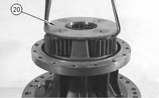
26. Install spacer (5) in carrier assembly (4).
27. Install sun gear (3) in carrier assembly
Illustration 19 g00869294 Illustration 20 g00869281 (4).Illustration 21
g00869266
28. Make sure that the mating surfaces of the ring gear and cover (2) are thoroughly clean.
29. Apply 1U-8846 Gasket Sealant on the flange surface of the ring gear and cover (5).
30. Install cover (2) and bolts (1).
End By:
a. Install the swing drive. Refer to Disassembly and Assembly, "Swing Drive - Remove and Install".
Shutdown SIS
Previous Screen
Product: EXCAVATOR
Model: 328D LCR EXCAVATOR RMX
Configuration: 328D LCR Excavator RMX00001-UP (MACHINE) POWERED BY C7 Engine
Disassembly and Assembly
328D Excavator Machine Systems
Swing Drive - Install
SMCS - 5459-012
Installation Procedure Table 1
Required Tools
1. Apply Tooling (D) on the locating pin and the pin bore in the main frame. Apply Tooling (E) on the mating surface of the main frame and the swing drive housing.
g00875735
2. Attach Tooling (B) and a suitable lifting device to swing drive (2), as shown. The weight of swing drive (2) is approximately 510 kg (1125 lb). Install swing drive (2) into the original position. Be careful not to damage the pinion gear.
Note: During installation, the locating pin for the swing drive can come out of the swing drive housing. The locating pin can be installed with a hammer after the swing drive is in place.
3. Use Tooling (A) to install bolts (1) that secure the swing drive to the main frame.
4. Before assembly, remove compound, oil, and dust from female threads, then apply Tooling (D) to the threads of bolts (1).
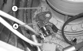
5. Tighten bolts (1) in an alternating sequence to a torque of 250 ± 25 N·m (184 ± 18 lb ft). Turn an additional angle of 45 ± 5 degrees. Refer to Service Magazine , M0083843 , "An Improved Bolt Tightening Procedure for the Critical Joints Is Now Used on all Excavators" for more detailed information.
6. Fill the swing drive with oil. Refer to Operation and Maintenance Manual, "Swing Drive Oil - Change".
End By:
Illustration 1 Illustration 2 g01206242Install the swing motor. Refer to Disassembly and Assembly, "Swing Motor - Install"
Previous Screen
Product: EXCAVATOR
Model: 328D LCR EXCAVATOR RMX
Configuration: 328D LCR Excavator RMX00001-UP (MACHINE) POWERED BY C7 Engine
Swing Gear and Bearing - Remove
SMCS - 7063-011
Removal Procedure
a. Remove the undercarriage frame. Refer to Disassembly and Assembly, "Upper Frame and Undercarriage Frame - Separate".
1. Remove all of the grease from the swing gear and bearing. Put the grease in a suitable container for storage or disposal.
g00520664
2. Put an alignment mark on swing gear and bearing (1) and on the undercarriage frame assembly for assembly purposes. Attach Tooling (A) and a suitable lifting device to swing gear and bearing (1), as shown. Apply slight lifting tension to the swing gear and bearing.
g00520670
3. Use Tooling (B) in order to remove bolts (2) and the spacers that hold swing gear and bearing (1) to the undercarriage frame.
4. Remove swing gear and bearing (1). The weight of the swing gear and bearing (1) is approximately 280 kg (615 lb).
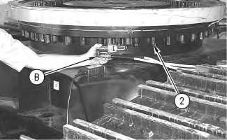
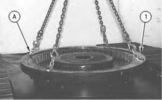 Illustration 1
Illustration 2
Illustration 1
Illustration 2
Suggest:
If the above button click is invalid.
Please download this document first, and then click the above link to download the complete manual.
Thank you so much for reading

Illustration 3
g00721855
Note: Inner dust seal (3) and outer dust seal (4) may have been installed dry in the swing gear and bearing or inner dust seal (3) and outer dust seal (4) may have been bonded to the swing gear and bearing.
5. Remove inner dust seal (3) and outer dust seal (4) from the swing gear and bearing.
6. Clean the seal grooves of the inner dust seal and the outer dust seal with a fine grit sandpaper. Use a cleaning solvent to clean the sealing grooves. Make sure that the seal grooves are thoroughly clean and dry prior to installing the new dust seals.