Shutdown SIS
Previous Screen
Product: EXCAVATOR
Model: 326F EXCAVATOR EBK
Configuration: 326F L Excavators EBK00001-UP (MACHINE) POWERED BY C7.1 Engine
Disassembly and Assembly
326F, 329F and 330F Excavators Machine Systems
Final Drive - Disassemble
SMCS - 4050-015
Disassembly Procedure
Table 1
Required Tools
Start By:
a. Remove the final drive.
1. Put an alignment mark across the sections of the final drive for assembly purposes. The parts must be reinstalled to the original locations.
g00892878
2. Use Tooling (G) and a suitable lifting device to position the final drive assembly onto Tooling (A). The weight of the final drive assembly is approximately 550 kg (1200 lb).
3. Remove bolts (1).
g00892883
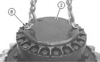
4. Use Tooling (B) and a suitable lifting device to remove cover (2). The weight of cover (2) is approximately 32 kg (70 lb).
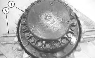 Illustration 1
Illustration 2
Illustration 3
g00892888
Illustration 1
Illustration 2
Illustration 3
g00892888
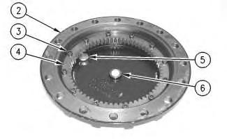
5. Remove bolts (3) and gear (4). Check plate (6). Replace plate (6) if plate (6) is worn. Remove plugs (5) from cover (2).
6. Remove O-ring seals (7) from plugs (5).
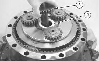
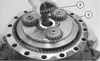
Remove gear (8) and spacer (9).
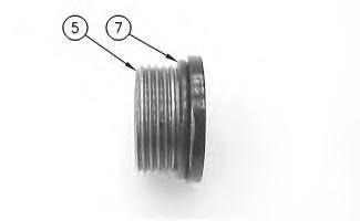 Illustration 4 g00892906
Illustration 5 g00892930
7.
Illustration 6 g00892965
Illustration 4 g00892906
Illustration 5 g00892930
7.
Illustration 6 g00892965
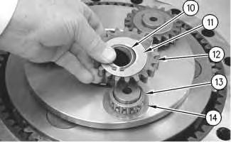
8. Use Tooling (C) to remove retaining ring (10). Remove washer (11) and gear (12). Remove bearing assembly (13) and washer (14).
9. Repeat Step 8 for the other two gear assemblies.
Illustration 7
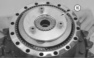
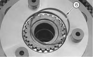
10. Remove retaining ring (15).
Illustration 8
11. Remove carrier assembly (16).
g00892968 g00892975Illustration 9 g02408860
12. Use a suitable press to remove the shafts from carrier assembly (16).
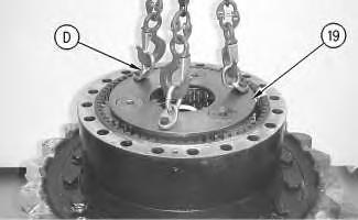
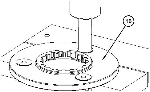
Illustration 10
13. Remove gear (17) and spacer (18).
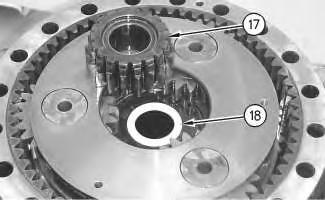
g00892977
Illustration 11
g00892997
14. Use Tooling (D) and a suitable lifting device to remove planetary carrier (19). The weight of planetary carrier (19) is approximately 48 kg (105 lb).
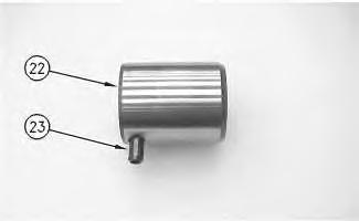
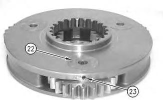
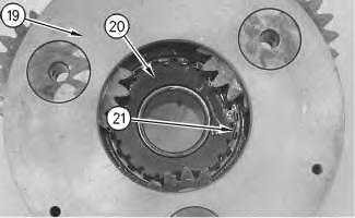 Illustration 12
g00893019
15. Remove retaining ring (21). Lift planetary carrier (19) off sun gear (20).
Illustration 13
g00896860
16. Drive spring pin (23) into planetary shaft (22).
Illustration 14
g00893043
Illustration 12
g00893019
15. Remove retaining ring (21). Lift planetary carrier (19) off sun gear (20).
Illustration 13
g00896860
16. Drive spring pin (23) into planetary shaft (22).
Illustration 14
g00893043
17. Remove planetary shaft (22). Use a suitable punch to remove spring pin (23) from planetary shaft (22).
Illustration 15
18. Remove washers (24) and bearing (25) from planetary gear (26).
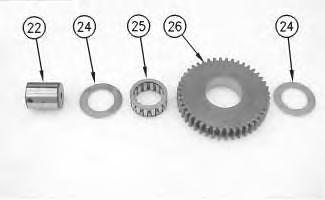
19. Repeat Steps 16 through 18 for the other two planetary gears.
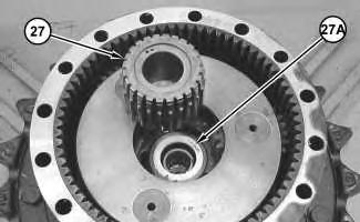
Illustration 16
20. Remove gear (27). Remove spacer (27A).
Illustration 17
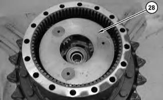
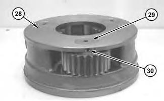
g00896863 g01842853 g0184297421. Use two people to remove carrier assembly (28). The weight of carrier assembly (28) is approximately 38 kg (85 lb).
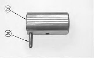
22. Drive spring pin (30) into shaft (29).
23. Remove shaft (29). Use a suitable punch to remove spring pin (30) from shaft (29).
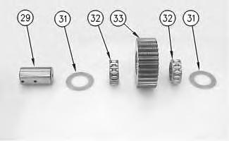
24. Remove washers (31) and bearings (32) from planetary gear (33).
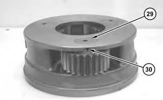 Illustration 18 g01843140
Illustration 19 g00893658
Illustration 20 g00893674
Illustration 18 g01843140
Illustration 19 g00893658
Illustration 20 g00893674
25. Repeat Steps 22 through 24 for the other three planetary gears.
26. Fasten Tooling (E) and a suitable lifting device to ring gear (34), as shown. Remove ring gear (34) from sprocket housing (35). The weight of ring gear (34) is approximately 66 kg (146 lb).
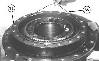
27. Remove O-ring seal (36) from sprocket housing (35).
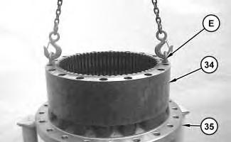 Illustration 21 g01208300
Illustration 22 g01208542
Illustration 23
g01208553
Illustration 21 g01208300
Illustration 22 g01208542
Illustration 23
g01208553
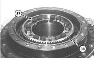
28. Remove bolts (37) from coupling gear (38).
29. Install Tooling (H) in coupling gear (38). Tighten the Tooling (H) evenly in order to loosen coupling gear (38). Remove the coupling gear from the motor housing.
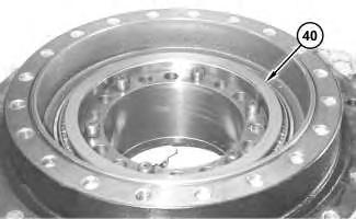
30. Remove shims (40) from the motor housing.
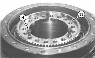 Illustration 24 g03431447
Illustration 25 g01208578
Illustration 26 g01208625
Illustration 24 g03431447
Illustration 25 g01208578
Illustration 26 g01208625
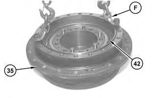
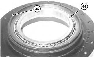
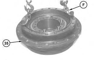
Note: Inner cones and outer bearing cones (42) and (44) are a slip fit on the motor housing. While you remove sprocket housing (35) from the motor housing, inner bearing cone (42) and outer bearing cones (44) may stay with the sprocket housing or the inner bearing cone may stay on the motor housing.
31. Fasten Tooling (F) and a suitable lifting device to sprocket housing (35). Separate the sprocket housing from the motor housing. The weight of sprocket housing (35) is approximately 109 kg (240 lb).
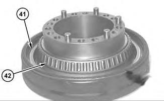
Illustration 27
g01208626
32. Remove the locating pins from the motor housing.
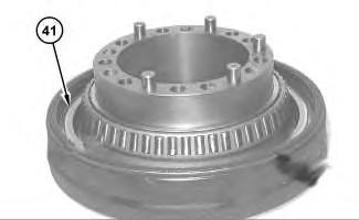
33. Remove Duo-Cone seal (41) from the motor housing.
34. If inner bearing cone (42) remained on the motor housing, then remove the inner bearing cone.
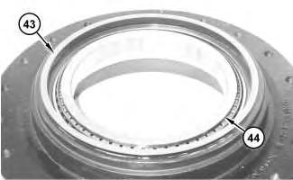
Illustration 28
g03431456
35. Remove Duo-Cone seal (43) from the sprocket housing.
36. If outer bearing cone (44) remained on the sprocket housing, then remove the outer bearing cone.
37. Remove the bearing cups from the sprocket housing.
Previous Screen
Product: EXCAVATOR
Model: 326F EXCAVATOR EBK
Configuration: 326F L Excavators EBK00001-UP (MACHINE) POWERED BY C7.1 Engine
Disassembly and Assembly
326F, 329F and 330F Excavators Machine Systems
Final Drive - Assemble
SMCS - 4050-016
Assembly Procedure
Required Tools
1. Make sure that all parts of the final drive are thoroughly clean and free of dirt and debris prior to assembly. Check the condition of all O-ring seals that are used in the final drive. If any of the seals are damaged, use new parts for replacement. Reassemble the final drive on Tooling (A).
Illustration 1
g03431464
Note: New final drives are equipped with angular contact ball bearings.
2. Apply Tooling (H) to the surfaces inside sprocket housing (35) that contacts the bearing cups. Install a bearing cup that is in each side of the sprocket housing with a press. Make sure that the bearing cups are properly seated.
3. Apply Tooling (H) to the surfaces inside the sprocket housing that contacts bearing cones (44).
4. Install outer bearing cone (44) in the sprocket housing.
Illustration 2
g01208625
5. Attach Tooling (F) and a suitable lifting device to sprocket housing (35). The weight of sprocket housing (35) is approximately 109 kg (240 lb). Install sprocket housing (35) on the motor housing. Carefully install inner bearing cone (42) on the sprocket housing.
g01208578
6. Adjust the bearing preload of the final drive. Determine the correct number of shims (40) that are required for the proper bearing preload, as follows:
Note: New final drives are equipped with angular contact ball bearings that require pre-load like the old roller bearings.
g01208987
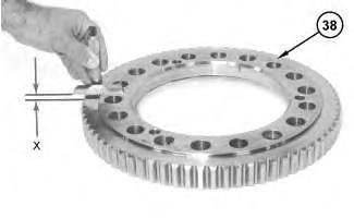
a. Use a depth micrometer to measure the step height of coupling gear (38) at several locations around the gear. Find the average for the measured dimensions around the gear and record the dimension. Call this Dimension (X).
b. Apply a load of 4000 kg (8820 lb) to the bearing cones.
c. Rotate sprocket housing (35) several times to seat the bearing cones.
d. Reduce the load to 1000 ± 100 kg (2205 ± 220 lb).
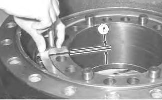
Illustration 3 Illustration 4e. With the bearing cones loaded, measure the distance between the top face of the motor housing and the top face of the bearing cone. Take measurements in several locations around the motor housing. Find the average of the measured dimensions, and record the dimensions. Call this Dimension (Y).
f. Determine the correct thickness of the shims which are used between the bearing cones and the coupling gear . Use the following equation to determine the shim pack thickness.
Shim pack thickness ... (Y) − (X) ± 0.05 mm (0.002 inch)
Note: If two shims are required, install the thinnest shim next to the coupling gear during final assembly.
7. Attach Tooling (F) and a suitable lifting device to sprocket housing (35). Separate sprocket housing (35) from the motor housing.
Reference: Refer to Disassembly and Assembly, "Duo-Cone Conventional Seals - Install".
Note: The rubber seals and all surfaces that contacts the seals must be clean and dry. After installation of the seals, put clean SAE 30 oil on the contact surfaces of the metal seals.
Illustration 5 g00631001 Illustration 6 g03431699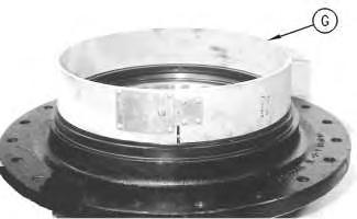
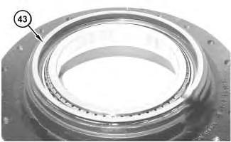
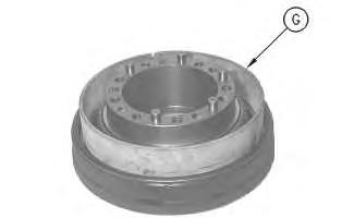 Illustration 7 g00631006
Illustration 8 g01208999
8. Use Tooling (G) to install Duo-Cone seal (43) in the sprocket housing.
Illustration 9 g00631014
Illustration 7 g00631006
Illustration 8 g01208999
8. Use Tooling (G) to install Duo-Cone seal (43) in the sprocket housing.
Illustration 9 g00631014
Illustration 10
g03431475
9. Use Tooling (G) to install Duo-Cone seal (41) in the motor housing.
10. Apply Tooling (H) in the bores for the locating pins that are in the motor housing. Reinstall the locating pins in the motor housing.
Illustration 11
g01208625
11. Make sure that inner bearing cone (42) is seated properly on the motor housing.
Note: Do not scratch Duo-Cone seal (41) or damage the Duo-Cone seal in the main housing, or the motor housing during assembly of the two components. After installation of the main housing on the motor housing, there will be a small gap between the components. The gap between the components is caused by the Duo-Cone seal. The gap will be eliminated during the installation of the coupling gear .
12. Fasten Tooling (F) and a suitable lifting device to sprocket housing (35). Carefully install the sprocket housing on the motor housing.
13. Install the outer bearing cone on the sprocket housing. Make sure that the outer bearing cone is properly seated.
Illustration 12
g01208578
14. Install shims (40) that were determined in Steps 6.a through 6.f on the end of the sprocket housing. If shims were required, make sure that the thinnest shim is installed on top.
Illustration 13
g01208553
15. Put coupling gear (38) in the original position on the motor housing.
16. Apply Tooling (J) on the threads of bolts (37) that hold coupling gear (38) in position. Tighten bolts (37) evenly and tighten the bolts in diagonally opposite pairs to a torque of 570 ± 80 N·m (420 ± 60 lb ft).
Illustration 14
g0120854217. Install O-ring seal (36) in sprocket housing (35).
18. Thoroughly clean the mating surface of sprocket housing (35) that contacts ring gear (34).
19. Apply a bead of Tooling (K) on the mating surface of ring gear (34).
20. Attach Tooling (E) and a suitable lifting device to ring gear (34). Put ring gear (34) in position on the sprocket housing. The weight of ring gear (34) is approximately 66 kg (146 lb). Make sure that the alignment mark upon the sprocket housing and the ring gear line with each other.
Illustration 15 g01208300
Illustration 16 g01843479
Illustration 17
g00893674
21. Assemble carrier assembly (28), as follows.
a. Install bearings (32) in planetary gear (33).
b. Install thrust washers (31) and planetary gear (33) in the carrier assembly.
c. Use a deburring tool to remove the metal burr from the openings in the carrier. Install planetary shaft (29) in the carrier assembly.
d. Drive spring pin (30) into planetary shaft (29).
Illustration 18
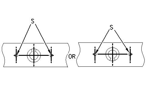
The stake mark is at position (S).
g00941047
e. Orient the split in spring pin (30) vertically to the carrier. Align the split in the spring pin to the top or to the bottom. Make a stake mark on each side of the spring pin hole in the carrier. Each stake mark should be approximately 2.25 ± 0.75 mm (0.089 ± 0.030 inch) from the outside diameter of the spring pin hole.
22. Repeat Steps 21.a through 21.e to install the other two planetary gears in the carrier assembly.
23. Use two people to install carrier assembly (28). The weight of carrier assembly (28) is approximately 38 kg (85 lb).
24. Install spacer (27A). Install gear (27).
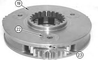 Illustration 19
g01842974
Illustration 20
g01842853
Illustration 21
g00897548
Illustration 19
g01842974
Illustration 20
g01842853
Illustration 21
g00897548
Illustration 22
g00896863
25. Assemble planetary carrier (19), as follows.
a. Install bearing (25) in planetary gear (26).
b. Install thrust washers (24) and planetary gear (26) in the planetary carrier.
c. Use a deburring tool to remove the metal burr from the openings in the carrier. Install planetary shaft (22) in planetary carrier (19).
d. Drive spring pin (23) into planetary shaft (22).
Illustration 23
The stake mark is at position (S).
g00941047
e. Orient the split in spring pin (23) vertically to the carrier. Align the split in the spring pin to the top or to the bottom. Make a stake mark on each side of the spring pin hole in the carrier. Each stake mark should be approximately 2.25 ± 0.75 mm (0.089 ± 0.030 inch) from the outside diameter of the spring pin hole.
f. Repeat Steps 25.a through 25.e to install the other two planetary gears in the carrier.
26. Position sun gear (20) in planetary carrier (19) and install retaining ring (21).
27. Use Tooling (D) and a suitable lifting device to install planetary carrier (19) into gear (34). The weight of planetary carrier (19) is approximately 48 kg (105 lb).
28. Install spacer (18) and gear (17).
Illustration 24
g00893019
Illustration 25
g00892997
Illustration 26
g00892977
Illustration 27
g01389807
Note: Make sure that the oil passages in the shafts are oriented toward the center of carrier assembly (16).
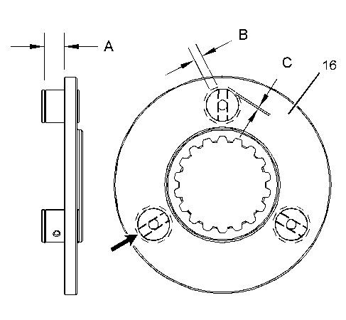
29. Raise the temperature of carrier assembly (16). Lower the temperature of the shafts. Install the shafts into carrier assembly (16) until the groove of the shafts is at Dimension (A). Dimension (A) equals 25.00 ± 0.10 mm (0.984 ± 0.004 inch).
30. Make eight stake marks at distance of Dimension (C) from each shaft. Dimension (C) equals 2.0 ± 1.0 mm (0.08 ± 0.04 inch). The width of each stake mark should be equal to Dimension (B). Dimension (B) equals 4.0 ± 1.0 mm (0.16 ± 0.04 inch).
Suggest:
If the above button click is invalid.
Please download this document first, and then click the above link to download the complete manual.
Thank you so much for reading

31. Install carrier assembly (16).
32. Install retaining ring (15).
33. Install washer (14) and bearing assembly (13). Install gear (12) and washer (11). Use Tooling (C) to install retaining ring (10).
34. Repeat Step 33 for the other two planetary gears.
Illustration 29
g00892968
Illustration 30
g00892965
Illustration 31
g00780428