325D, 325D L and 325D LN Excavator
Service Repair Manual Models
F
Start By:
1H-3112
1P-5551
F
Start By:
1H-3112
1P-5551
1
a. Remove the final drive. Refer to Disassembly and Assembly, "Final Drive - Remove".
Note: Cleanliness is an important factor. Before the disassembly procedure, the exterior of the component should be thoroughly cleaned. This will prevent dirt from entering the internal mechanism.
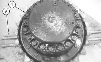
1. Put an alignment mark across the sections of the final drive for assembly purposes. The parts must be reinstalled in the part's original locations.
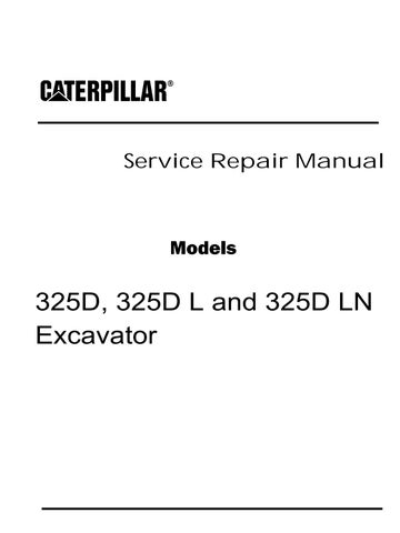
2. Fasten the final drive to Tooling (A), as shown. The combined weight of the final drive and final drive sprocket is approximately 312 kg (688 lb).
3. Remove bolts (1) and the washers that hold the cover in position.
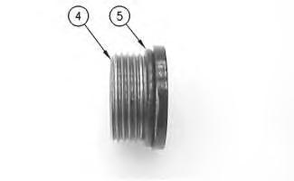
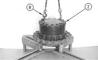
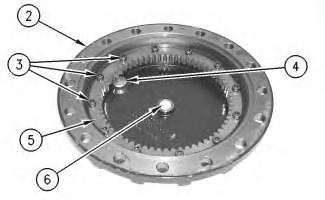
4. Remove the setscrews from the cover. Fasten Tooling (B) and a suitable lifting device to cover (2), as shown. The weight of cover (2) is approximately 32 kg (70 lb). Remove cover (2).
5. Remove thrust plate (3) from cover (2).
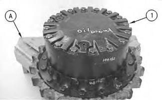
6. Remove plugs (4) from cover (2).
Illustration 2 g00708090 Illustration 3 g00708091Illustration 4 g00708235
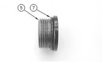
7. Remove O-ring seals (5) from both plugs (4) that were in the cover.
Illustration 5 g00708092
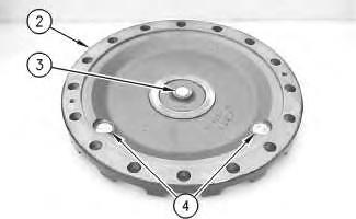
8. Remove spacer (6) from carrier assembly (7).
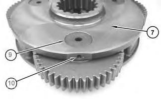
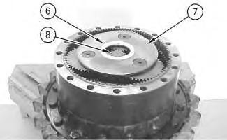
9. Remove sun gear (8) from carrier assembly (7).
10. Remove carrier assembly (7) by lifting the carrier assembly straight up. The weight of carrier assembly (7) is approximately 14 kg (30 lb).
Illustration 6 g01304883
11. Disassemble carrier assembly (7), as follows.
a. Drive spring pin (10) into planetary shaft (9) with a hammer and a punch.
Illustration 7
g00708144
b. Remove planetary shaft (9) with spring pin (10) from the carrier assembly.
c. Remove spring pin (10) from planetary shaft (9) with a hammer and a punch.
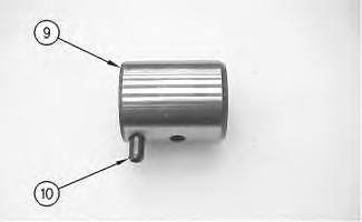
Illustration 8
g00708218
d. Remove thrust washers (11) and planetary gear (13) from the carrier assembly.
e. Remove bearing (12) from planetary gear (13).
12. Repeat Steps 11.a through 11.e in order to remove the remaining planetary gears from the carrier assembly.
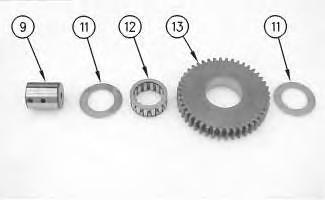
Illustration 9
g00708162
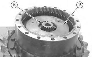
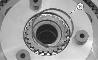
13. Remove sun gear (14) from carrier assembly (15).
Illustration 10
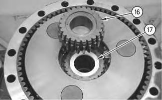
14. Remove spacer (16).
g00708325
Illustration 11
g00708184
Note: It will be necessary to pry ring gears (17) away from main housing (18) in order to install the lifting slings.
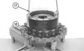
15. Fasten a suitable lifting device to ring gears (17), as shown. Remove the ring gears from main housing (18). The weight of ring gears (17) is approximately 45 kg (100 lb).
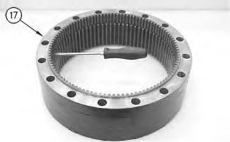
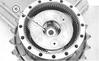
Illustration 12 g00708360
16. Use a screwdriver or a chisel in order to separate the two ring gears (17).
Note: The two ring gears are held together with Tooling (F). It may be necessary to heat the ring gears in order to soften the sealant. Do not heat over 135 °C (275 °F) for more than thirty minutes.
Illustration 13 g00708172
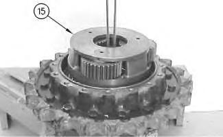
17. Position a 12.7 mm (0.50 inch) shackle under carrier assembly (15).
18. Fasten a suitable lifting device to the shackle.
19. Slowly lift carrier assembly (15) from the final drive. The weight of carrier assembly (15) is approximately 39 kg (85 lb).
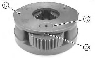
20. Disassemble carrier assembly (15), as follows.
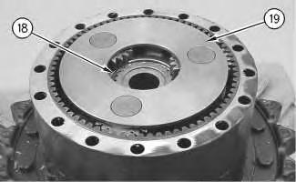
Illustration 14
a. Drive spring pin (20) into planetary shaft (19) with a hammer and a punch.
g00708175b. Remove planetary shaft (19) with spring pin (20) from the carrier assembly.
c. Remove spring pin (20) from planetary shaft (19) with a hammer and a punch.

d. Remove thrust washers (21) and planetary gear (23) from the carrier assembly.
e. Remove bearings (22) from planetary gear (23).
21. Repeat Steps 20.a through 20.e in order to remove the remaining planetary gears from the carrier.
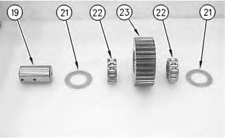 Illustration 15 g00708370
Illustration 16 g00708220
Illustration 15 g00708370
Illustration 16 g00708220
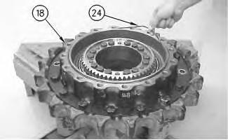
Illustration 17 g00708186
22. Remove O-ring seal (24) from main housing (18).
Illustration 18 g00708187
23. Remove bolts (25) from gear (26).
Illustration 19 g00708202
24. Use Tooling (C) in order to remove gear (26) from main housing (18).
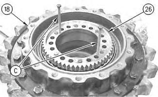
Note: The motor housing will separate from the main housing (18) once gear (26) is removed. Make sure that the motor housing is supported.
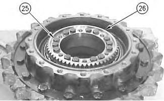
Illustration 20
g00708211
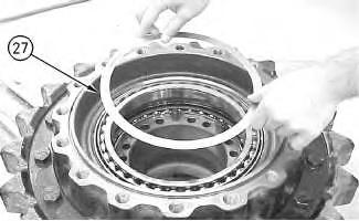
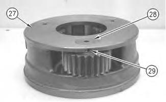
25. Remove shims (27) from the main housing.
Illustration 21
g00708212
26. Fasten Tooling (D) and a suitable lifting device to main housing (18), as shown.
27. Use a hammer and a punch in order to separate main housing (18) and the final drive sprocket from the motor housing (28). The combined weight of main housing (18) and the final drive sprocket is approximately 82 kg (180 lb).
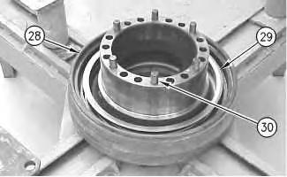
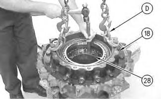
Illustration 22
g00708214
28. Remove Duo-Cone seal (29) from motor housing (28).
29. Remove alignment pins (30).
Illustration 23
g00708215
Illustration 24
g00708216
30. Remove Duo-Cone seal (31) from main housing (18).
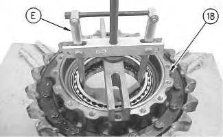
31. Use Tooling (E) in order to remove bearings (32) and (33) from the main housing.
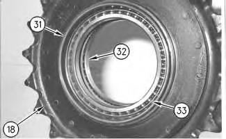
32. If necessary, remove the final drive sprocket from the main housing.
33. Refer to Disassembly and Assembly, "Final Drive Sprocket - Remove and Install".
Copyright 1993 - 2020 Caterpillar Inc.
All Rights Reserved.
Private Network For SIS Licensees.
Mon Jun 22 10:27:07 UTC+0800 2020
Previous Screen
Product: EXCAVATOR
Model: 325D EXCAVATOR GPB
Configuration: 325D L & LN Excavator GPB00001-UP (MACHINE) POWERED BY C7 Engine
Disassembly and Assembly
324D, 325D, 326D and 329D Excavators and 329D MHPU Mobile Hydraulic Power Unit Machine Systems
SMCS - 4050-015
S/N - A3R1-1021
S/N - AZP1-UP
S/N - DBH1-UP
S/N - EJC1-643
S/N - GBR1-UP
S/N - GPB1-801
S/N - JJG1-813
S/N - KBE1-UP
S/N - LAB1-415
S/N - LAL1-250
S/N - MCL1-201
S/N - NAC1-250
S/N - PAL1-UP
S/N - PKE1-814
S/N - SCR1-774
S/N - SYM1-617
S/N - T2D1-322
S/N - T2S1-UP
a. Remove the final drive. Refer to Disassembly and Assembly, "Final Drive - Remove".
Note: Cleanliness is an important factor. Before the disassembly procedure, the exterior of the component should be thoroughly cleaned. This will prevent dirt from entering the internal mechanism.
Note: Some of the images that are in this procedure do not show the sprocket assembly that is attached to the final drive housing. If necessary, the weights that are given include the weight of the sprocket assembly.
1. Put an alignment mark across the sections of the final drive for assembly purposes. The parts must be reinstalled in the part's original locations.
g00708089
2. Fasten the final drive to Tooling (A), as shown. The weight of the final drive assembly is approximately 312 kg (688 lb).
3. Remove bolts (1) and the washers that hold the cover in position.
g00708090
4. Remove the setscrews from the cover. Fasten Tooling (B) and a suitable lifting device to cover (2), as shown. Remove the cover. The weight of the cover is approximately 32 kg (70 lb).
g00879362
Illustration 1
Illustration 2
Illustration 3
5. Remove bolts (3). Remove gear (5). Check plate (6). Replace plate (6) if wear is shown. Remove plugs (4) from cover (2).
6. Remove O-ring seal (7) from plugs (4).

7. Remove gear (8). Remove spacer (9).
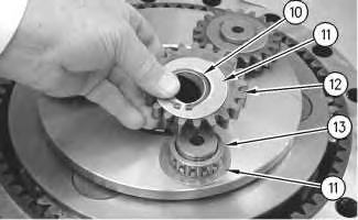
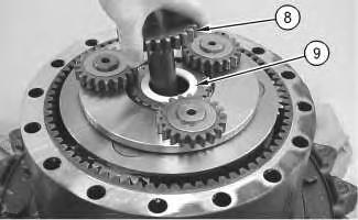 Illustration 4
g00879365
Illustration 5
g00780428
Illustration 6
g00780432
Illustration 4
g00879365
Illustration 5
g00780428
Illustration 6
g00780432
8. Remove retaining ring (10) with Tooling (C). Remove washer (11). Remove gear (12). Remove bearing assembly (13). Remove second washer (11).
9. Repeat Step 8 for the remaining two gear assemblies.
Illustration 7 g00781401
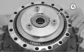
10. Remove retaining ring (14).
Illustration 8 g00781407
11. Remove carrier assembly (15).
Illustration 9 g01389593
12. Use a suitable press in order to remove the shafts from carrier assembly (15).
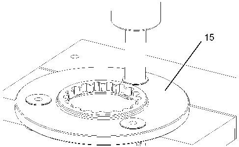
Illustration 10
13. Remove gear (16). Remove spacer (17).
g00781412
Illustration 11
g00781466
14. Remove retaining ring (18).

15. Remove carrier assembly (19).
16. Disassemble carrier assembly (19), as follows.
a. Drive spring pin (20) into planetary shaft (21) with a hammer and a punch.
b. Remove planetary shaft (21).
c. Remove spring pin (20) from planetary shaft (21) with a hammer and a punch.
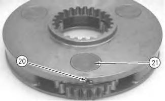 Illustration 12 g00879368
Illustration 13 g00781476
Illustration 12 g00879368
Illustration 13 g00781476
Illustration 14 g00781516
d. Remove thrust washers (22) and planetary gear (24) from the carrier assembly.
e. Remove bearing (23) from planetary gear (24).
17. Repeat Steps 16.a through 16.e for the other two planetary.
Illustration 15
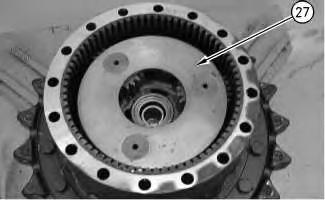
18. Remove gear (25). Remove spacer (26).
16
19. Remove carrier assembly (27).
20. Use two people to remove carrier assembly (27). The weight of the carrier assembly is approximately 38 kg (85 lb).
21. Disassemble carrier assembly (27), as follows.
g00781529 Illustration g00781559Illustration 17
a. Drive spring pin (29) into planetary shaft (28) with a hammer and a punch.
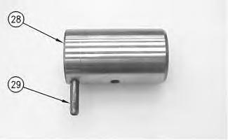
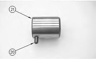
Illustration 18 g00781601
b. Remove planetary shaft (28).
c. Remove spring pin (29) from planetary shaft (28) with a hammer and a punch.
Illustration 19 g00781607
d. Remove thrust washers (30) and planetary gear (32) from the carrier assembly.
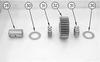
e. Remove two bearings (31) from the planetary gear.
22. Repeat Steps 21.a through 21.e for the other two planetary gears.
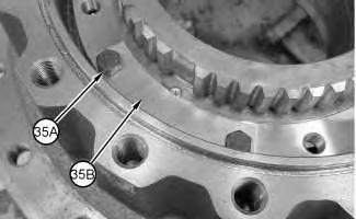
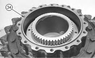
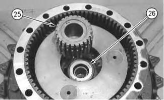
Illustration 20
23. Use two people to remove gear (33). The weight of gear is approximately 41 kg (90 lb).
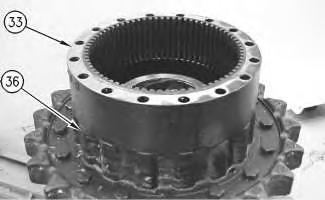
Illustration 21
24. Remove O-ring seal (34).
Illustration 22
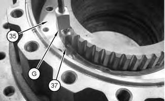
25. Remove bolts (35A) and plates (35B).
g00781730 g00781807 g0114765026. Use Tooling (G) to remove dowel (37) from stopper plate (35).
24
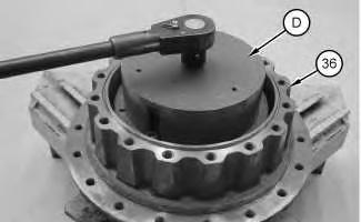
27. Secure Tooling (D) to stopper plate (35). Use Tooling (D) to remove stopper plate (35).
25
28. Use Tooling (E) and a suitable lifting device to remove housing (36). The weight of housing (36) is approximately 100 kg (220 lb).
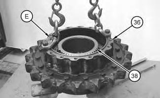 Illustration 23
g01147651
Illustration
g01147759
Illustration
g01147930
Illustration 23
g01147651
Illustration
g01147759
Illustration
g01147930
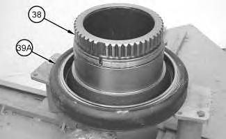
29. Remove Duo-Cone seal (39A) from housing (38).
30. Remove Duo-Cone seal (39B) from housing (36).
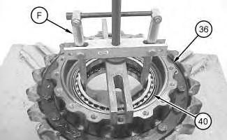
31. Use Tooling (F) in order to remove bearings (40) and (41) from housing (36).
32. If necessary, remove the final drive sprocket from the sprocket housing. Refer to Disassembly and Assembly, "Final Drive Sprocket - Remove and Install".
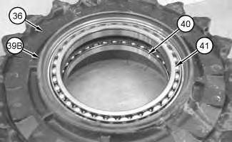 Illustration 26 g01147951
Illustration 27
g01147975
Illustration 28 g01147934
Illustration 26 g01147951
Illustration 27
g01147975
Illustration 28 g01147934
Shutdown SIS
Previous Screen
Product: EXCAVATOR
Model: 325D EXCAVATOR GPB
Configuration: 325D L & LN Excavator GPB00001-UP (MACHINE) POWERED BY C7 Engine
Disassembly and Assembly
324D, 325D, 326D and 329D Excavators and 329D MHPU Mobile Hydraulic Power Unit Machine Systems
SMCS - 4050-015
S/N - A3R1022-UP
S/N - BFC1-UP
S/N - BYS1-UP
S/N - CYW1-UP
S/N - CZF1-UP
S/N - DBH380-UP
S/N - DJF1-UP
S/N - DTZ1-UP
S/N - EBM1-UP
S/N - EJC644-UP
S/N - GPB802-UP
S/N - J8D1-UP
S/N - J9D1-UP
S/N - JAT1-UP
S/N - JHJ1-UP
S/N - JJG814-UP
S/N - JZR1-UP
S/N - KBE241-UP
S/N - L5G1-UP
S/N - LAB416-UP
S/N - LAL251-UP
S/N - MCL202-UP
S/N - MNB1-UP
S/N - MND1-UP
S/N - NAC251-UP
S/N - PKE815-UP
S/N - PYT1-UP
S/N - RSK1-UP
S/N - SCR775-UP
S/N - SCY1-UP
S/N - SYM618-UP
S/N - T2D323-UP
S/N - TPM1-UP
S/N - TRH1-UP
S/N - TSN1-UP
S/N - WDK1-UP
S/N - WLT1-UP
S/N - XDB1-UP
S/N - YFW1-UP
Table 1 Required Tools
Start By:
a. Start by removing the final drive. Refer to Disassembly and Assembly, "Final DriveRemove".
Note: Cleanliness is an important factor. Before the disassembly procedure, the exterior of the component should be thoroughly cleaned. This will prevent dirt from entering the internal mechanism.
1. Put an alignment mark across the sections of the final drive for assembly purposes. The parts must be reinstalled to the original locations.
Illustration 1
g00892878
2. Use Tooling (G) and a suitable lifting device to position the final drive assembly onto Tooling (A). The weight of the final drive assembly is approximately 550 kg (1200 lb).
3. Remove bolts (1).
Suggest:
If the above button click is invalid.
Please download this document first, and then click the above link to download the complete manual.
Thank you so much for reading

Illustration 2
4. Use Tooling (B) and a suitable lifting device to remove cover (2). The weight of cover (2) is approximately 32 kg (70 lb).
Illustration 3
5. Remove bolts (3) and gear (4). Check plate (6). Replace plate (6) if plate (6) is worn. Remove plugs (5) from cover (2).
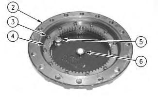
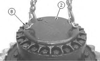
Illustration 4
6. Remove O-ring seals (7) from plugs (5).
 g00892883
g00892888
g00892906
g00892883
g00892888
g00892906