Shutdown SIS
Previous Screen
Product: MOBILE HYD POWER UNIT
Model: 325D L MOBILE HYD POWER UNIT H3N
Configuration: 325D L Mobile Hydraulic Power Unit H3N00001-UP (MACHINE) POWERED BY C7 Engine
Disassembly and Assembly
C7
Engines for Caterpillar Built Machines
Inlet and Exhaust Valves - Remove and Install
SMCS - 1105-010
Removal Procedure
Table 1
Required Tools
Tool Part Number Part Description Qty
A 5S-1330 Valve Spring Compressor 1
Start By:
a. Remove the cylinder head assembly. Refer to Disassembly and Assembly, "Cylinder HeadRemove".
NOTICE
Keep all parts clean from contaminants.
Contaminants may cause rapid wear and shortened component life.
The valve spring keepers can be thrown from the valve when the valve spring compressor is released. Ensure that the valve spring keepers are properly installed on the valve stem. To help prevent personal injury, keep away from the front of the valve spring keepers and valve springs during the installation of the valves.
Note: The following components of the exhaust valves are different from the components of the inlet valves: spring retainer (5), valve spring (4) and valve (2).
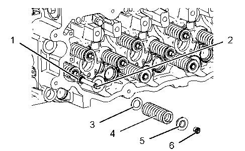
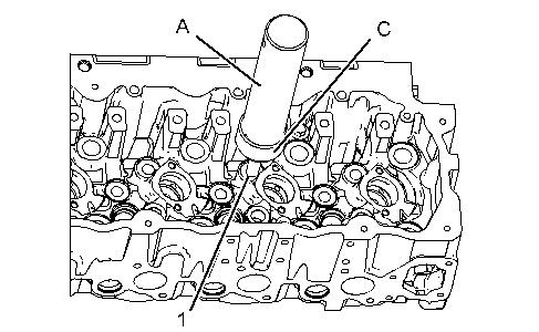
1. Use Tooling (A) to compress valve spring (4). Remove retainer locks (6).
2. Remove Tooling (A). Remove spring retainer (5), valve spring (4), and washer (3).
3. Remove valve seal (1) and valve (2).
Installation Procedure
Table 2
Required Tools
Keep all parts clean from contaminants.
Contaminants may cause rapid wear and shortened component life.
Improper assembly of parts that are spring loaded can cause bodily injury.
To prevent possible injury, follow the established assembly procedure and wear protective equipment.
1. Lubricate valve (2) with clean engine oil. Install valve (2) in the cylinder head assembly. Install new valve seal (1) against the valve guide.
2. Place the following items on the valve stem: washer (3), valve spring (4) and spring retainer (5).
Note: A small amount of grease can be used to hold the retainer locks in position during installation.
3. Use Tooling (A) to compress valve spring (4). Install retainer locks (6).
End By:
a. Install the cylinder head assembly. Refer to Disassembly and Assembly, "Cylinder HeadInstall".
Copyright 1993 - 2020 Caterpillar Inc.
Shutdown SIS
Previous Screen
Product: MOBILE HYD POWER UNIT
Model: 325D L MOBILE HYD POWER UNIT H3N
Configuration: 325D L Mobile Hydraulic Power Unit H3N00001-UP (MACHINE) POWERED BY C7 Engine
Disassembly and Assembly
C7
Engines for Caterpillar Built Machines
Inlet and Exhaust Valve Guides - Remove and Install
SMCS - 1104-010
Removal Procedure Table 1
Required Tools
Start By:
A. Remove the inlet and exhaust valves. Refer to Disassembly and Assembly, "Inlet and Exhaust Valves - Remove and Install".
NOTICE
Keep all parts clean from contaminants.
Contaminants may cause rapid wear and shortened component life.
g01124395
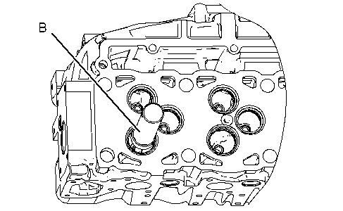
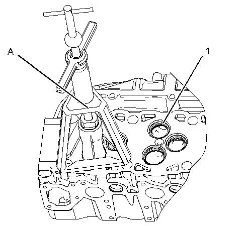
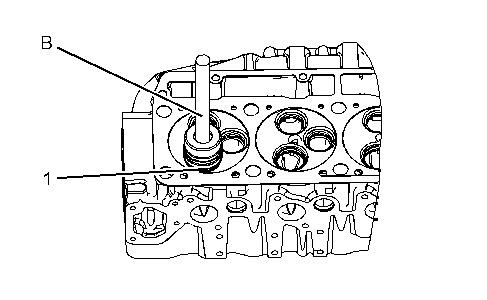
1. Use Tooling (A) to remove the inlet valve guides from the cylinder head assembly. Use Tooling (B) to remove the exhaust valve guides from the cylinder head assembly.
Installation Procedure
NOTICE
Keep all parts clean from contaminants.
Contaminants may cause rapid wear and shortened component life.
Illustration 2
g01124397
Note: Position the valve guides and tap on the top of the valve guides in order to start the valve guides into the cylinder head assembly.
1. Use Tooling (A) and Tooling (C) to install inlet valve guides (1) . Install inlet valve guides (1) until the protrusion is 23.0 ± 0.50 mm (0.90 ± 0.020 inch) above the cylinder head assembly.
2. Use Tooling (B) and Tooling (D) to install the exhaust valve guides. Install the exhaust valve guides until the protrusion is 24.05 ± 0.5 mm (1.0 ± 0.02 inch) above the cylinder head assembly.
End By: Install the inlet and exhaust valves. Refer to Disassembly and Assembly, "Inlet and Exhaust Valves - Remove and Install".
Shutdown SIS
Previous Screen
Product: MOBILE HYD POWER UNIT
Model: 325D L MOBILE HYD POWER UNIT H3N
Configuration: 325D L Mobile Hydraulic Power Unit H3N00001-UP (MACHINE) POWERED BY C7 Engine
Disassembly and Assembly
C7
Engines for Caterpillar Built Machines
Inlet and Exhaust Valve Seat Inserts - Remove and Install
SMCS - 1103-010
Removal Procedure Table 1
Required Tools
(1)
Start By:
a. Remove the inlet and exhaust valves. Refer to Disassembly and Assembly, "Inlet and Exhaust Valves - Remove and Install".
NOTICE
Keep all parts clean from contaminants.
Contaminants may cause rapid wear and shortened component life.
1. Lower the temperature of new valve seat inserts (1).
2. Use Tooling (B) and a suitable press to install the new valve seat inserts in the cylinder head.
Note: Do not machine the prefinished valve seat inserts in order to correct the valve stem projection. An excessive valve stem projection indicates that the valve seat insert is not seated or material was not cleaned from the bottom of the counterbore.
End By:
a. Install the inlet valves and exhaust valves. Refer to Disassembly and Assembly, "Inlet and Exhaust Valves - Remove and Install".
Shutdown SIS
Previous Screen
Product: MOBILE HYD POWER UNIT
Model: 325D L MOBILE HYD POWER UNIT H3N
Configuration: 325D L Mobile Hydraulic Power Unit H3N00001-UP (MACHINE) POWERED BY C7 Engine
Disassembly and Assembly
C7
Engines for Caterpillar Built Machines
Engine Oil Filter Base and Oil Cooler - Remove
SMCS - 1306-011; 1378-012
Removal Procedure
NOTICE
Care must be taken to ensure that fluids are contained during performance of inspection, maintenance, testing, adjusting and repair of the product. Be prepared to collect the fluid with suitable containers before opening any compartment or disassembling any component containing fluids.
Refer to Special Publication, NENG2500, "Caterpillar Tools and Shop Products Guide" for tools and supplies suitable to collect and contain fluids on Caterpillar products.
Dispose of all fluids according to local regulations and mandates.
NOTICE
Keep all parts clean from contaminants.
Contaminants may cause rapid wear and shortened component life.
Remote Mounted Engine Oil Filter Base
Table 1
Required Tools
Tool Part Number Part Description
A 185-3630 Strap Wrench As 1
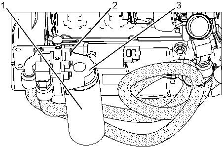
Illustration 1 g01152338
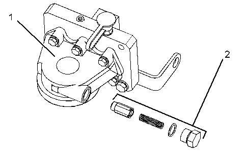
1. Use Tooling (A) to remove engine oil filter (1) .
2. Remove bolts (2) and engine oil filter base (3) .
Engine Mounted Engine Oil Filter Base
1. Drain the coolant from the cooling system into a suitable container for storage or disposal. Refer to Operation and Maintenance Manual, "Cooling System Coolant - Change".
2. Disconnect hose assemblies (4) .
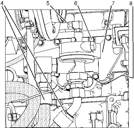
3. Disconnect hose assembly (5) .
4. Remove bolts (6) and engine oil filter base (7) .
5. Remove oil cooler (8) and the gasket from the engine.
Shutdown SIS
Previous Screen
Product: MOBILE HYD POWER UNIT
Model: 325D L MOBILE HYD POWER UNIT H3N
Configuration: 325D L Mobile Hydraulic Power Unit H3N00001-UP (MACHINE) POWERED BY C7 Engine
Disassembly and Assembly
C7
Engines for Caterpillar Built Machines
Engine Oil Filter Base - Disassemble
SMCS - 1306-015
Disassembly Procedure
Start By:
A. Remove the engine oil filter base and the oil cooler. Refer to Disassembly and Assembly, "Engine Oil Filter Base and Oil Cooler - Remove".
NOTICE
Keep all parts clean from contaminants.
Contaminants may cause rapid wear and shortened component life.
Remote Mounted Engine Oil Filter Base
Personal injury can result from being struck by parts propelled by a released spring force.
Make sure to wear all necessary protective equipment.
Follow the recommended procedure and use all recommended tooling to release the spring force.
Personal injury can result from being struck by parts propelled by a released spring force.
Make sure to wear all necessary protective equipment.
Follow the recommended procedure and use all recommended tooling to release the spring force.
Previous Screen
Product: MOBILE HYD POWER UNIT
Model: 325D L MOBILE HYD POWER UNIT H3N
Configuration: 325D L Mobile Hydraulic Power Unit H3N00001-UP (MACHINE) POWERED BY C7 Engine
Disassembly and Assembly
C7
Engines for Caterpillar Built Machines
Engine Oil Filter Base - Assemble
SMCS - 1306-016
Assembly Procedure
NOTICE
Keep all parts clean from contaminants.
Contaminants may cause rapid wear and shortened component life.
Engine Mounted Engine Oil Filter Base
Table 1
Required Tools
Tool Part Number Part Description Qty
A 155-0695
Thread Lock Compound 1
Shutdown SIS
Improper assembly of parts that are spring loaded can cause bodily injury.
To prevent possible injury, follow the established assembly procedure and wear protective equipment.
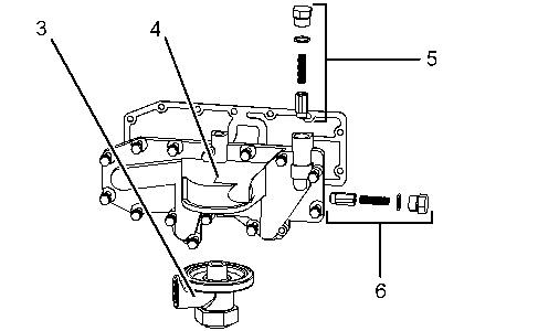
1. Install oil filter bypass valve (6) and oil filter bypass valve (5) in engine oil filter base (4) .
2. Apply Tooling (A) to the threads of adapter (3). Install the O-ring seals and adapter (3). Tighten adapter (3) to a torque of 150 ± 20 N·m (110 ± 15 lb ft).
Remote Mounted Engine Oil Filter Base
Improper assembly of parts that are spring loaded can cause bodily injury.
To prevent possible injury, follow the established assembly procedure and wear protective equipment.
1. Install oil filter bypass valve (2) in engine oil filter base (1) .
End By: Install the engine oil filter base and the oil cooler. Refer to Disassembly and Assembly, "Engine Oil Filter Base and Oil Cooler - Install".
Copyright 1993 - 2020 Caterpillar Inc.
All Rights Reserved.
Private Network For SIS Licensees.
Previous Screen
Product: MOBILE HYD POWER UNIT
Model: 325D L MOBILE HYD POWER UNIT H3N
Configuration: 325D L Mobile Hydraulic Power Unit H3N00001-UP (MACHINE) POWERED BY C7 Engine
Disassembly and Assembly
C7
Engines for Caterpillar Built Machines
Engine Oil Filter Base and Oil Cooler - Install
SMCS - 1306-012; 1378-012
Installation Procedure
NOTICE
Keep all parts clean from contaminants.
Contaminants may cause rapid wear and shortened component life.
Engine Mounted Engine Oil Filter Base
Shutdown SIS
1. Position the gasket and oil cooler (8) on the engine.
2. Install engine oil filter base (7) and bolts (6) .
3. Connect hose assembly (5) .
4. Connect hose assemblies (4) .
5. Fill the cooling system. Refer to Operation and Maintenance Manual, "Cooling System Coolant - Change".
Remote Mounted Engine Oil Filter Base
Illustration 2
1. Position engine oil filter base (3) and install bolts (2) .
2. Install engine oil filter (1) .
g01152338
Shutdown SIS
Previous Screen
Product: MOBILE HYD POWER UNIT
Model: 325D L MOBILE HYD POWER UNIT H3N
Configuration: 325D L Mobile Hydraulic Power Unit H3N00001-UP (MACHINE) POWERED BY C7 Engine
Disassembly and Assembly
C7
Engines for Caterpillar Built Machines
Engine Oil Pump - Remove
SMCS - 1304-011
Removal Procedure
Start By:
A. Remove the engine oil pan. Refer to Disassembly and Assembly, "Engine Oil Pan - Remove and Install".
NOTICE
Keep all parts clean from contaminants.
Contaminants may cause rapid wear and shortened component life.
Illustration 1 g01152440
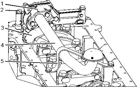
1. Remove bracket (5) .
2. Remove pickup tube (4) and the gasket from engine oil pump (1) .
3. Remove outlet elbow (3) and the O-ring seals from engine oil pump (1) .
4. Remove bolts (2) and engine oil pump (1) .
Shutdown SIS
Previous Screen
Product: MOBILE HYD POWER UNIT
Model: 325D L MOBILE HYD POWER UNIT H3N
Configuration: 325D L Mobile Hydraulic Power Unit H3N00001-UP (MACHINE) POWERED BY C7 Engine
Disassembly and Assembly
C7
Engines for Caterpillar Built Machines
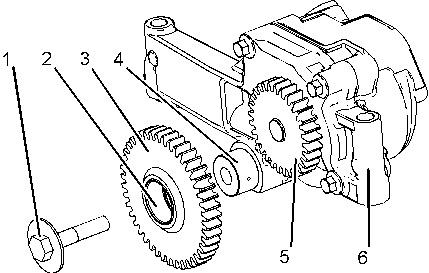
Engine Oil Pump - Disassemble
SMCS - 1304-015
Disassembly Procedure Table 1
Required Tools
Start By:
A. Remove the engine oil pump. Refer to Disassembly and Assembly, "Engine Oil PumpRemove".
NOTICE
Keep all parts clean from contaminants.
Contaminants may cause rapid wear and shortened component life.
Suggest:
If the above button click is invalid.
Please download this document first, and then click the above link to download the complete manual.
Thank you so much for reading

1. Remove bolt (1) .
2. Remove idler gear (3) from shaft (4) .
3. Use Tooling (B) and remove bearing (2) from idler gear (3) .
4. Use Tooling (A) to remove drive gear (5) from engine oil pump (6) .