Start By:
a. Start by removing the final drive. Refer to Disassembly and Assembly, "Final DriveRemove".
Note: Cleanliness is an important factor. Before the disassembly procedure, the exterior of the component should be thoroughly cleaned. This will prevent dirt from entering the internal mechanism.
1. Put an alignment mark across the sections of the final drive for assembly purposes. The parts must be reinstalled to the original locations.
Illustration 1
g00892878
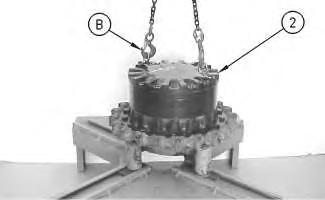
2. Use Tooling (G) and a suitable lifting device to position the final drive assembly onto Tooling (A). The weight of the final drive assembly is approximately 550 kg (1200 lb).
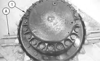
3. Remove bolts (1).
Illustration 2
4. Use Tooling (B) and a suitable lifting device to remove cover (2). The weight of cover (2) is approximately 32 kg (70 lb).
Illustration 3
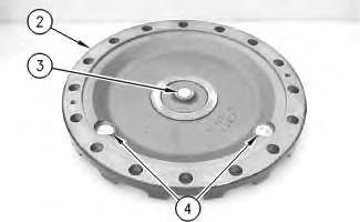
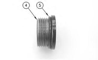
5. Remove bolts (3) and gear (4). Check plate (6). Replace plate (6) if plate (6) is worn. Remove plugs (5) from cover (2).
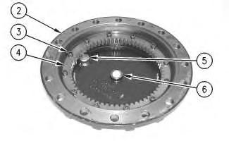
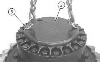
Illustration 4
6. Remove O-ring seals (7) from plugs (5).
 g00892883
g00892888
g00892906
g00892883
g00892888
g00892906
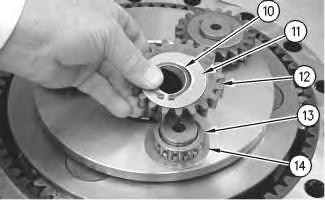
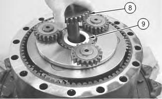
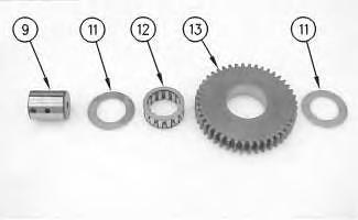
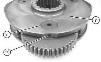
7. Remove gear (8) and spacer (9).
8. Use Tooling (C) to remove retaining ring (10). Remove washer (11) and gear (12). Remove bearing assembly (13) and washer (14).
9. Repeat Step 8 for the other two gear assemblies.
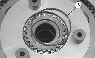
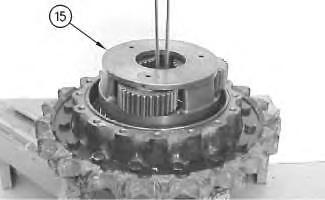
10. Remove retaining ring (15).
Illustration 5 g00892930 Illustration 6 g00892965 Illustration 7 g00892968Illustration 8 g00892975
11. Remove carrier assembly (16).
Illustration 9 g01389804
12. Use a suitable press to remove the shafts from carrier assembly (16).
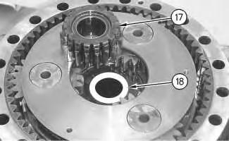
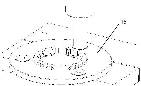
Illustration 10 g00892977

13. Remove gear (17) and spacer (18).
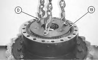
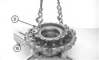
14. Use Tooling (D) and a suitable lifting device to remove planetary carrier (19). The weight of planetary carrier (19) is approximately 48 kg (105 lb).
Illustration 12
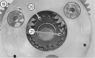
15. Remove retaining ring (21). Lift planetary carrier (19) off sun gear (20).
16. Drive spring pin (23) into planetary shaft (22).
Illustration 11 g00892997 g00893019 Illustration 13 g00896860Illustration 14 g00893043
17. Remove planetary shaft (22). Use a suitable punch to remove spring pin (23) from planetary shaft (22).
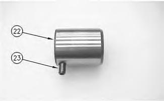
Illustration 15 g00896863
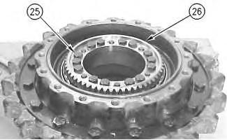
18. Remove washers (24) and bearing (25) from planetary gear (26).
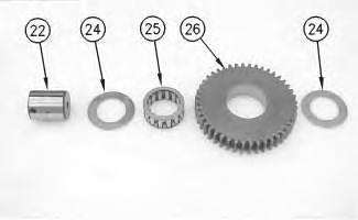
19. Repeat Steps 16 through 18 for the other two planetary gears.
Illustration 16 g01842853
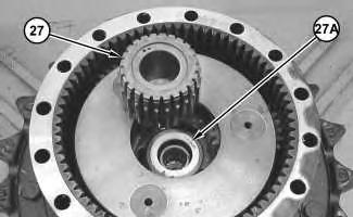
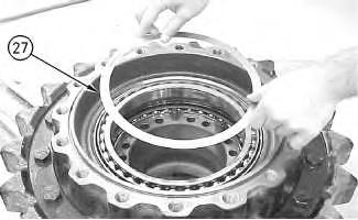
20. Remove gear (27). Remove spacer (27A).
Illustration 17 g01842974
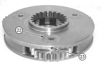
21. Use two people to remove carrier assembly (28). The weight of carrier assembly (28) is approximately 38 kg (85 lb).
Illustration 18 g01843140
22. Drive spring pin (30) into shaft (29).
Illustration 19 g00893658
23. Remove shaft (29). Use a suitable punch to remove spring pin (30) from shaft (29).

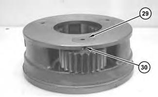
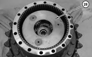
Illustration 20 g00893674
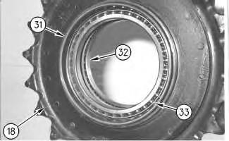
24. Remove washers (31) and bearings (32) from planetary gear (33).
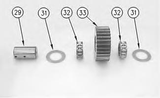
25. Repeat Steps 22 through 24 for the other three planetary gears.
Illustration 21 g01208300
26. Fasten Tooling (E) and a suitable lifting device to ring gear (34), as shown. Remove ring gear (34) from sprocket housing (35). The weight of ring gear (34) is approximately 66 kg (146 lb).

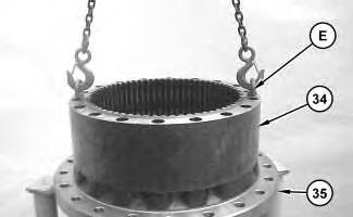 Illustration 22 g01208542
27. Remove O-ring seal (36) from sprocket housing (35).
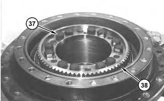
28. Remove bolts (37) from coupling gear (38).
29. Install suitable forcing bolts (39) in coupling gear (38). Tighten the forcing bolts evenly in order to loosen coupling gear (38). Remove the coupling gear from the motor housing.

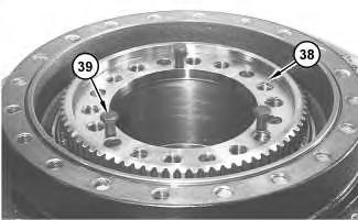 Illustration 23
g01208553
Illustration 24
g01208572
Illustration 25
g01208578
Illustration 23
g01208553
Illustration 24
g01208572
Illustration 25
g01208578
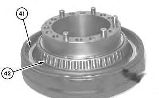
30. Remove shims (40) from the motor housing.
Note: Inner cones and outer bearing cones (42) are a slip fit on the motor housing. While you remove sprocket housing (35) from the motor housing, inner bearing cone (42) may stay with the sprocket housing or the inner bearing cone may stay on the motor housing.
31. Fasten Tooling (F) and a suitable lifting device to sprocket housing (35). Separate the sprocket housing from the motor housing. The weight of sprocket housing (35) is approximately 109 kg (240 lb).
32. Remove the locating pins from the motor housing.
33. Remove Duo-Cone seal (41) from the motor housing.
34. If inner bearing cone (42) remained on the motor housing, then remove the inner bearing cone.
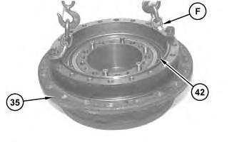 Illustration 26 g01208625
Illustration 27 g01208626
Illustration 26 g01208625
Illustration 27 g01208626
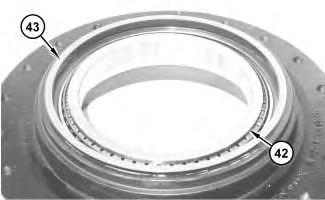
35. Remove Duo-Cone seal (43) from the sprocket housing.
36. If inner bearing cone (42) remained on the sprocket housing, then remove the inner bearing cone.
37. Remove the bearing cups from the sprocket housing.
Shutdown SIS
Previous Screen
Product: EXCAVATOR
Model: 325D EXCAVATOR PKE
Configuration: 325D L & LN Excavator PKE00001-UP (MACHINE) POWERED BY C7 Engine
Disassembly and Assembly
324D, 325D, 326D and 329D Excavators and 329D MHPU Mobile Hydraulic Power Unit Machine Systems
Final Drive - Assemble
SMCS - 4050-016
S/N - A3R1-UP
S/N - AZP1-UP
S/N - BFC1-UP
S/N - BYS1-UP
S/N - CZF1-UP
S/N - DBH1-UP
S/N - DJF1-UP
S/N - DTZ1-UP
S/N - EBM1-UP
S/N - EJC1-UP
S/N - GBR1-UP
S/N - GPB1-UP
S/N - GPK1-UP
S/N - JAT1-UP
S/N - JHJ1-UP
S/N - JJG1-UP
S/N - JZR1-UP
S/N - KBE1-UP
S/N - LAB1-UP
S/N - LAL1-UP
S/N - MCL1-UP
S/N - MNB1-UP
S/N - MND1-UP
S/N - NAC1-UP
S/N - PJM1-UP
S/N - PKE1-UP
S/N - PYT1-UP
S/N - RSK1-UP
S/N - SCR1-UP
S/N - SYM1-UP
S/N - T2D1-UP
S/N - T2S1-UP
S/N - TPM1-UP
S/N - TRH1-UP
S/N - TSN1-UP
S/N - TZL1-UP
S/N - XDB1-UP
S/N - YFW1-UP
Assembly Procedure
A 1P-2420 Transmission Repair Stand 1
B 138-7573 Link Bracket 2
D 138-7574 Link Bracket 2
G 126-3994 Duo-Cone Seal Installer 1
H 5P-3931 Anti-Seize Compound
F 1U-8846 Gasket Sealant
Note: Cleanliness is an important factor. Before assembly, all parts should be cleaned in cleaning fluid. Allow the parts to air dry. Wiping cloths or rags should not be used to dry parts. Lint may be deposited on the parts which may cause later trouble. Inspect all parts. If any parts are worn or damaged, use new parts for replacement. All disassembly and all assembly procedures must be performed on a clean work surface and in a clean hydraulic area. Keep cleaned parts covered and protected at all times.
Note: O-rings, gaskets, and seals should always be replaced. A used O-ring may not have the same sealing properties as a new O-ring. Use 1U-6396 O-Ring Assembly Compound during the assembly procedure.
Note: Apply a light film of hydraulic oil to all components before assembly.
1. Install the final drive sprocket if the sprocket was removed from the main housing.
2. Refer to Disassembly and Assembly, "Final Drive Sprocket - Remove and Install".
Illustration 1
3. Apply Tooling (H) to the outer diameter of the bearings.
4. Install bearings (32) and (33) in main housing (18) with a suitable press.
5. Make sure that bearing (32) and bearing (33) contact the counterbore in the main housing.
6. Use the following procedure to preload the bearings and determine the correct thickness of shims.
 g00708215
Illustration 2
g00713058
a. Fasten Tooling (D) and a suitable lifting device to main housing (18) . Install the main housing on the motor housing.
b. Put the main housing and the motor housing in a suitable press.
Illustration 3
(a) Bearing surface
(b) Housing surface
g00709278
c. Use a suitable press and a spacer in order to apply a load of 4000 kg (8818.5 lb) on the bearings. Rotate the housing in order to seat the bearings.
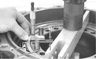
d. Reduce the load on the bearings to 1000 ± 100 kg (2204.6 ± 220.5 lb).
e. Use a depth micrometer in order to measure the step length between the bearing surface and the housing surface. Take measurements at several different locations around the housing. Compute the average of the measured dimensions and record the number. Call this Dimension (Y) .
g00709276
f. Use a depth micrometer in order to measure the step length of the coupling gear (26) . Take measurements at several different locations around the gear. Compute the average of the measured dimensions and record the number. Call this Dimension (X) .
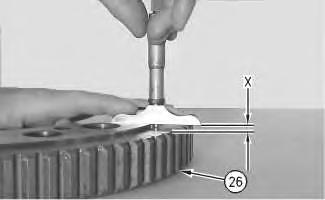
g. The thickness of the shims is equal to (X - Y) ± 0.05 mm (0.002 inch).
Note: Use no more than two shims. If two shims are required, install the thinner shim next to the gear.
h. Remove the main housing from the motor housing.
7. Use Tooling (G) in order to install Duo-Cone seal (31) in main housing (18) . Refer to Disassembly and Assembly, "Duo-Cone Conventional Seals - Install".
Note: The rubber seals and all surfaces that contact the seals must be clean and dry. After installation of the seals, put clean SAE 30 oil on the contact surfaces of the metal seals.
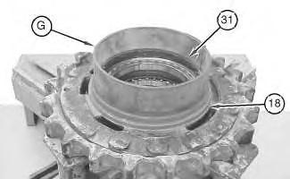 Illustration 4
Illustration 5
g01021370
Illustration 4
Illustration 5
g01021370
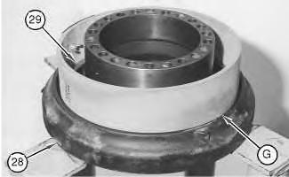
8. Use Tooling (G) in order to install Duo-Cone seal (29) in motor housing (28) .
9. Apply Tooling (H) to the surfaces that contact pins (30) .
10. Install alignment pins (30) .
Note: Do not damage the Duo-Cone seals in the main housing or in the motor housing during the assembly of the two components. After installation of the main housing on the motor housing, there will be a small gap between the components. The gap is caused by the Duo-Cone seals. This gap will be eliminated during installation of gear (26) .
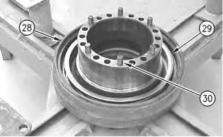 Illustration 6 g01021371
Illustration 7 g00708214
Illustration 6 g01021371
Illustration 7 g00708214
g00713058
11. Fasten Tooling (D) and a suitable lifting device to main housing (18) . Install the main housing on the motor housing.
g00708211
12. Install shims (27) that were determined in Step 6.g in the main housing.
Note: If two shims are required, install the thinner shim next to the gear.
Illustration 8 Illustration 9Illustration 10
13. Install gear (26) .
14. Install bolts (25) in gear (26) . Install the bolts in an even pattern until the gear is seated against the bearing. Tighten bolts (25) in a crisscross pattern.
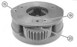
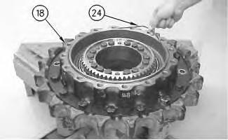
Illustration 11
15. Install O-ring seal (24) to main housing (18) .
Illustration 12 g00708175
16. Assemble carrier assembly (15) , as follows.
Illustration 13 g00708220
a. Install bearings (22) in planetary gear (23) .
b. Install thrust washers (21) and planetary gear (23) in the carrier assembly.
c. Use a deburring tool in order to remove the metal burr from the openings in the carrier. Install planetary shaft (19) in the carrier assembly.
d. Drive spring pin (20) into planetary shaft (19) with a hammer and a punch.
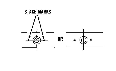
Illustration 14 g00513451
e. Orient the split in spring pin (20) vertically to the carrier. Align the split in the spring pin to the top or to the bottom. Make a stake mark on each side of the spring pin hole in the carrier. Each stake mark should be approximately 1.50 mm (0.059 inch) from the outside diameter of the spring pin hole.
17. Repeat Steps 16.a through 16.e in order to install the remaining planetary gears in the carrier assembly.
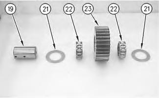
Illustration 15
g00708172
18. Install a lifting sling through the middle of carrier assembly (15) . Fasten a 12.7 mm (0.50 inch) shackle to the suitable lifting device.
19. Install carrier assembly (15) on the final drive. The weight of carrier assembly (15) is approximately 39 kg (85 lb).
20. Remove the shackle and the suitable lifting device.
Illustration 16
g00713148
21. Apply Tooling (F) to the mating surface of ring gear (17b) .
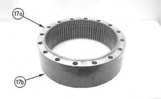
22. Install ring gear (17a) on ring gear (17b) .
23. Fasten a suitable lifting device to ring gears (17) , as shown. Install the ring gears to main housing (18) . The weight of ring gears (17) is approximately 45 kg (100 lb).
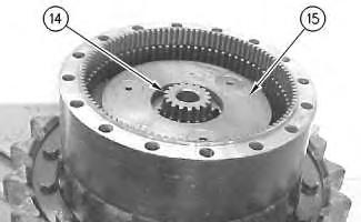
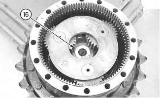
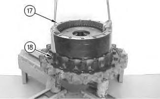 Illustration 17 g00708184
Illustration 18 g00708325
24. Install spacer (16) in the carrier assembly.
Illustration 19 g00708162
Illustration 17 g00708184
Illustration 18 g00708325
24. Install spacer (16) in the carrier assembly.
Illustration 19 g00708162
25. Install sun gear (14) in carrier assembly (15) .
26. Assemble carrier assembly (7) , as follows.
a. Install bearing (12) in planetary gear (13) .
b. Install thrust washers (11) and planetary gear (13) in the carrier assembly.
c. Install planetary shaft (9) in the carrier assembly.
d. Drive spring pin (10) into planetary shaft (9) with a hammer and a punch.
Illustration 20 g01304883 Illustration 21 g00708218Illustration 22 g00513451
e. Orient the split in spring pin (10) vertically to the carrier. Align the split in the spring pin to the top or to the bottom. Make a stake mark on each side of the spring pin hole in the carrier. Each stake mark should be approximately 1.50 mm (0.059 inch) from the outside diameter of the spring pin hole.
27. Repeat Steps 26.a through 26.e in order to install the remaining planetary gears in the carrier assembly.
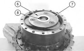
Illustration 23 g00708092
28. Install carrier assembly (7) in the ring gear. The weight of carrier assembly (7) is approximately 14 kg (30 lb).
29. Install sun gear (8) in carrier assembly (7) .
30. Install spacer (6) in carrier assembly (7) .
Suggest:
If the above button click is invalid.
Please download this document first, and then click the above link to download the complete manual.
Thank you so much for reading

Illustration 24
g00708235
31. Install new O-ring seals (5) on plugs (4) that were in the cover.
Illustration 25
g00708091
32. Install plugs (4) in cover (2) . Tighten plugs (4) to a torque of 80 ± 10 N·m (59 ± 7 lb ft).
33. Install thrust plate (3) in cover (2) .
34. Apply Tooling (F) to the mating surface of the ring gear.