Service
Previous Screen
Product: MOBILE HYD POWER UNIT
Model: 325C MOBILE HYD POWER UNIT MSG
Configuration: 325C Mobile Hydraulic Power Unit MSG00001-UP (MACHINE) POWERED BY 3126B Engine
Disassembly and Assembly
3126B Engines for Caterpillar Built Machines Media
Crankshaft Main Bearings - Install
SMCS - 1203-012
Installation Procedure Table 1
Required Tools Tool
NOTICE
Keep all parts clean from contaminants.
Contaminants may cause rapid wear and shortened component life.
Shutdown SIS
i01518323
Note: Place clean engine oil on the crankshaft main bearings prior to assembly. Ensure that the tabs on the back side of the crankshaft main bearings fit in the grooves of the crankshaft main bearing caps and the cylinder block.
g00516920
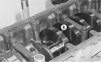
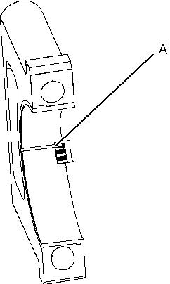
1. Use Tool (A) and install the upper halves of the crankshaft main bearings in the cylinder block. Do not put oil on the back of the crankshaft main bearing.
g00610152
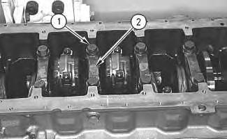
2. Install the lower halves of the crankshaft main bearings in crankshaft main bearing caps (2). Do not put oil on the back of the crankshaft main bearing.
NOTICE
Crankshaft main bearing caps should be installed with the part number toward the right side of the engine. Crankshaft main bearing caps are to be identified by stamped numbers 1 through 7 located on the bottom surface. The thrust plate is used on the number 6 crankshaft main bearing only.
3. Place crankshaft main bearing caps (2) in position on the cylinder block. Place clean engine oil or Molylube on the bolt threads and on the washer face. Install bolts (1).
4. Tighten bolts (1) to a torque of 54 ± 7 N·m (40 ± 5 lb ft). Tighten each bolt (1) for an additional 90 ± 5 degrees (1/4 turn).
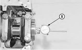
Illustration 1 Illustration 25. Check the end play of the crankshaft with Tool (B). The end play must be 0.07 mm (0.003 inch) to 0.32 mm (0.013 inch).
End By:
a. Install the engine oil pump. Refer to Disassembly and Assembly, "Engine Oil PumpInstall".
Copyright 1993 - 2020 Caterpillar Inc. All Rights Reserved. Private Network For SIS Licensees.
Shutdown SIS
Previous Screen
Product: MOBILE HYD POWER UNIT
Model: 325C MOBILE HYD POWER UNIT MSG
Configuration: 325C Mobile Hydraulic Power Unit MSG00001-UP (MACHINE) POWERED BY 3126B Engine
Disassembly and Assembly
3126B Engines for Caterpillar Built Machines
Crankshaft - Remove
SMCS - 1202-011
Removal Procedure
Start By:
a. Remove the flywheel housing. Refer to Disassembly and Assembly, "Flywheel HousingRemove and Install".
b. Remove the engine oil pump. Refer to Disassembly and Assembly, "Engine Oil PumpRemove".
c. Remove the front housing. Refer to Disassembly and Assembly, "Housing (Front)Remove".
NOTICE
Keep all parts clean from contaminants.
Contaminants may cause rapid wear and shortened component life.
1. Remove main bearing caps (2).
2. Remove connecting rod caps (3).
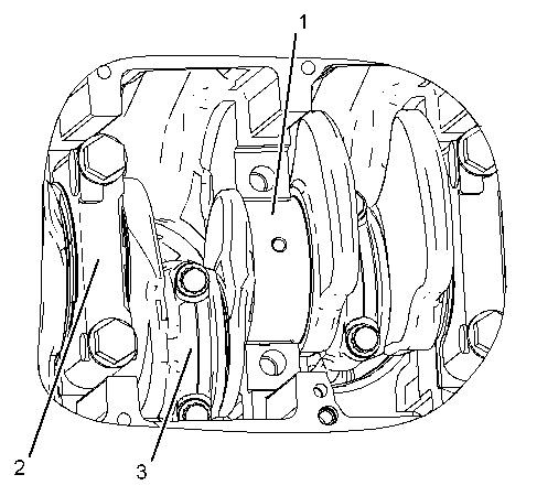 Illustration 1 g01028042
Illustration 2 g01184978
Illustration 1 g01028042
Illustration 2 g01184978
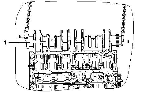
3. Put identification marks on the gear train for installation purposes. Attach a suitable lifting device to each end of crankshaft (1). Carefully remove crankshaft (1) from the cylinder block. The weight of crankshaft (1) is approximately 60 kg (132 lb).
Shutdown SIS
Previous Screen
Product: MOBILE HYD POWER UNIT
Model: 325C MOBILE HYD POWER UNIT MSG
Configuration: 325C Mobile Hydraulic Power Unit MSG00001-UP (MACHINE) POWERED BY 3126B Engine
Disassembly and Assembly
3126B Engines for Caterpillar Built Machines
Crankshaft Wear Sleeve (Rear) - Remove - If Equipped
SMCS - 1161-011-ZV
Removal Procedure Table 1
Required Tools
Start By:
a. Remove the crankshaft rear seal. Refer to Disassembly and Assembly, "Crankshaft Rear Seal - Remove".
NOTICE
Keep all parts clean from contaminants.
Contaminants may cause rapid wear and shortened component life.
g00614029
Note: Wear sleeves are not installed at the factory. The wear sleeve is included with the replacement rear seal.
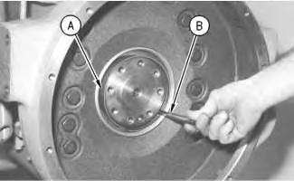
1. Install Tooling (A) in the bore of the crankshaft rear sleeve.
2. Install Tooling (B) between Tooling (A) and the crankshaft wear sleeve. Turn Tooling (B) until the edge of Tooling (B) makes a crease in the crankshaft wear sleeve. Make a crease in the crankshaft wear sleeve at two other locations around the crankshaft wear sleeve until the crankshaft wear sleeve is loose.
3. Remove Tooling (B), Tooling (A), and the crankshaft wear sleeve from the end of the crankshaft.
Previous Screen
Product: MOBILE HYD POWER UNIT
Model: 325C MOBILE HYD POWER UNIT MSG
Configuration: 325C Mobile Hydraulic Power Unit MSG00001-UP (MACHINE) POWERED BY 3126B Engine
Disassembly and Assembly
3126B Engines for Caterpillar Built Machines
Crankshaft Wear Sleeve (Rear) - Install
SMCS - 1161-012-ZV
Installation Procedure Table 1
Required Tools
NOTICE
Keep all parts clean from contaminants.
Contaminants may cause rapid wear and shortened component life.
Shutdown SIS
i01929732
1. Ensure that the rear of the crankshaft is thoroughly clean and dry prior to the installation of the crankshaft rear seal.
Illustration 1
g01003875
2. Fasten Tooling (C) to the rear of the crankshaft with Tooling (D). Hand tighten Tooling (D).
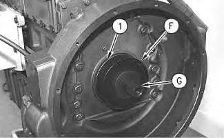
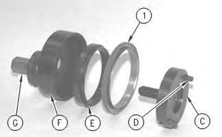
3. Position the crankshaft rear seal and crankshaft rear sleeve (1) on Tooling (C). Position Tooling (E) on Tooling (C).
Illustration 2
Typical example
g01003866
4. Position Tooling (F) over Tooling (C) and Tooling (E). Install Tooling (G). Tighten Tooling (G) in order to install the crankshaft rear seal and the crankshaft wear sleeve.
5. Remove Tooling (G), Tooling (F), and Tooling (E). Turn over Tooling (E). Install Tooling (E), Tooling (F), and Tooling (G). Tighten Tooling (G) in order to complete the installation of the crankshaft rear seal and the crankshaft wear sleeve.
6. Remove Tooling (G) and Tooling (F). Check Tooling (E) and Tooling (C). The faces of Tooling (E) and Tooling (C) will be flush if the crankshaft rear seal and the crankshaft wear sleeve are properly installed. Refer to the Specifications module for more information.
7. Remove Tooling (E), Tool (E), and Tooling (C).
End By:
a. Install the flywheel. Refer to Disassembly and Assembly, "Flywheel - Install".
Previous Screen
Product: MOBILE HYD POWER UNIT
Model: 325C MOBILE HYD POWER UNIT MSG
Configuration: 325C Mobile Hydraulic Power Unit MSG00001-UP (MACHINE) POWERED BY 3126B Engine
Disassembly and Assembly
3126B Engines for Caterpillar Built Machines
Crankshaft - Install
SMCS - 1202-012
Installation Procedure Table 1
Required Tools
Tool Part Number Part Description
A 8T-5096 Dial Indicator Group 1
NOTICE
Keep all parts clean from contaminants.
Contaminants may cause rapid wear and shortened component life.
Shutdown SIS
NOTICE
Ensure that the crankshaft main bearing tabs engage with the grooves in the block and the crankshaft main bearing cap.
Note: The number six main bearing is the thrust bearing.
1. Clean the bearing surfaces in the cylinder block for the main bearings. Apply clean engine oil on the upper main bearing. Do not put engine oil on the back side of the bearing
surfaces. Install the upper main bearing in the cylinder block. Ensure that the tab on the back side of the bearing engages with the groove in the cylinder block.
2. Put clean engine oil on the journals of the crankshaft bearing. Attach a suitable lifting device to crankshaft (1). The weight of crankshaft (1) is approximately 60 kg (132 lb). Carefully install the crankshaft in the cylinder block.
3. Clean the bearing surface of the main bearing caps. Install the lower main bearing in the crankshaft main bearing caps. Ensure that the tab on the back side of the bearing engages with the groove in the main bearing cap. Apply clean engine oil on the lower main bearing. Do not put engine oil on the back side of the bearing surfaces.
4. Install crankshaft main bearing caps with the part numbers toward the right hand side of the cylinder block. The numbers should start at the front of the engine. Place clean engine oil or Molylube on the bolt threads and the washers.
Illustration 1 g01184978
Illustration 2
g01028042
5. Install the bolts for main bearing caps (2). Tighten the bolts to a torque of 54 ± 7 N·m (40 ± 5 lb ft).
6. Turn the bolts for an additional 90 ± 5 degrees (1/4 turn).
7. Install connecting rod caps (3). Refer to Disassembly and Assembly, "Pistons and Connecting Rods - Install".
8. Check the end play of crankshaft (1) with Tooling (A). The end play must be 0.07 to 0.32 mm (0.003 to 0.013 inch).
End By:
a. Install the front housing. Refer to Disassembly and Assembly, "Housing (Front) - Install".
b. Install the engine oil pump. Refer to Disassembly and Assembly, "Engine Oil PumpInstall".
c. Install the flywheel housing. Refer to Disassembly and Assembly, "Flywheel HousingRemove and Install".
Copyright 1993 - 2020 Caterpillar Inc. All Rights Reserved. Private Network For SIS Licensees.
Shutdown SIS
Previous Screen
Product: MOBILE HYD POWER UNIT
Model: 325C MOBILE HYD POWER UNIT MSG
Configuration: 325C Mobile Hydraulic Power Unit MSG00001-UP (MACHINE) POWERED BY 3126B Engine
Disassembly and Assembly
3126B Engines for Caterpillar Built Machines
Crankshaft Gear - Remove and Install
SMCS - 1204-010-GE
Removal Procedure Table 1
Required Tools
Start By:
a. Remove the crankshaft. Refer to Disassembly and Assembly, "Crankshaft - Remove".
NOTICE
Keep all parts clean from contaminants.
Contaminants may cause rapid wear and shortened component life.
1. Use Tooling (A) in order to remove crankshaft gear (3) from crankshaft (1).
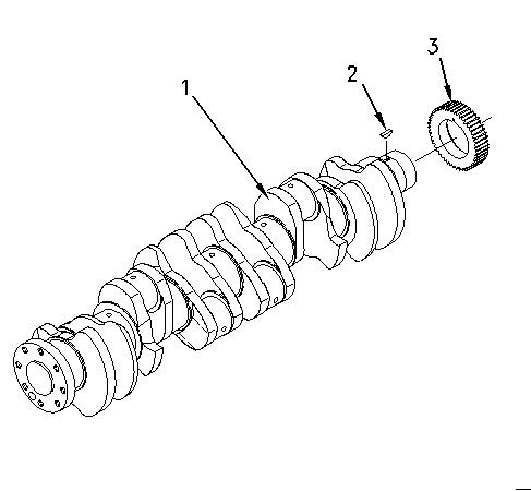
2. Remove woodruff key (2).
Installation Procedure
NOTICE
Keep all parts clean from contaminants.
Contaminants may cause rapid wear and shortened component life.
Illustration 2
1. Position woodruff key (2) in crankshaft (1).
g00988783
Hot oil and hot components can cause personal injury. Do not allow hot oil or hot components to contact the skin.
2. Raise the temperature of crankshaft gear (3). Install crankshaft gear (3) on crankshaft (1).
End By:
a. Install the crankshaft. Refer to Disassembly and Assembly, "Crankshaft - Install".
Copyright 1993 - 2020 Caterpillar Inc.
Previous Screen
Product: MOBILE HYD POWER UNIT
Model: 325C MOBILE HYD POWER UNIT MSG
Configuration: 325C Mobile Hydraulic Power Unit
Disassembly and Assembly
3126B Engines for Caterpillar Built Machines
Bearing Clearance - Check
SMCS - 1203-535; 1219-535
Measurement Procedure
Table 1
Required Tools
(MACHINE) POWERED BY 3126B Engine
Note: Plastic gauge may not be necessary when the engine is in the chassis.
NOTICE
Keep all parts clean from contaminants.
Contaminants may cause rapid wear and shortened component life.
Shutdown SIS
Note: Cat does not recommend the checking of the actual bearing clearances particularly on small engines. This is because of the possibility of obtaining inaccurate results and the possibility of damaging the bearing or the journal surfaces. Each Cat engine bearing is quality checked for specific wall thickness.
Note: The measurements should be within specifications and the correct bearings should be used. If the crankshaft journals and the bores for the block and the rods were measured during disassembly, no further checks are necessary. However, if the technician still wants to measure the bearing clearances, Tooling (A) is an acceptable method. Tooling (A) is less accurate on journals with small diameters if clearances are less than 0.10 mm (0.004 inch).
NOTICE
Lead wire, shim stock or a dial bore gauge can damage the bearing surfaces.
The technician must be very careful to use Tooling (A) correctly. The following points must be remembered:
• Ensure that the backs of the bearings and the bores are clean and dry.
• Ensure that the bearing locking tabs are properly seated in the tab grooves.
• The crankshaft must be free of oil at the contact points of Tooling (A).
1. Put a piece of Tooling (A) on the crown of the bearing that is in the cap.
Note: Do not allow Tooling (A) to extend over the edge of the bearing.
2. Use the correct torque-turn specifications in order to install the bearing cap. Do not use an impact wrench. Be careful not to dislodge the bearing when the cap is installed.
Note: Do not turn the crankshaft when Tooling (A) is installed.
3. Carefully remove the cap, but do not remove Tooling (A). Measure the width of Tooling (A) while Tooling (A) is in the bearing cap or on the crankshaft journal. Refer to Illustration 1.
Illustration 1
Typical Example
g01152855
4. Remove all of Tooling (A) before you install the bearing cap.
Note: When Tooling (A) is used, the readings can sometimes be unclear. For example, all parts of Tooling (A) are not the same width. Measure the major width in order to ensure that the parts are within the specification range. Refer to Specifications Manual, "Connecting Rod Bearing Journal" and Specifications Manual, "Main Bearing Journal" for the correct clearances.
Copyright 1993 - 2020 Caterpillar Inc. All Rights Reserved. Private Network For SIS Licensees.
Previous Screen
Product: MOBILE HYD POWER UNIT
Model: 325C MOBILE HYD POWER UNIT MSG
Configuration: 325C Mobile Hydraulic Power Unit
Disassembly and Assembly
3126B Engines for Caterpillar Built Machines
Idler Pulley - Remove and Install
SMCS - 1358-010
Illustration 1
Copyright 1993 - 2020 Caterpillar Inc. All Rights Reserved. Private Network For SIS Licensees.
(MACHINE) POWERED BY 3126B Engine
Shutdown SIS
Previous Screen
Product: MOBILE HYD POWER UNIT
Model: 325C MOBILE HYD POWER UNIT MSG
Configuration: 325C Mobile Hydraulic Power Unit MSG00001-UP (MACHINE) POWERED BY 3126B Engine
Disassembly and Assembly
3126B Engines for Caterpillar Built Machines Media
Belt Tensioner - Remove and Install
SMCS - 1358-010
Removal Procedure
Illustration 1
Shutdown SIS
g01011962
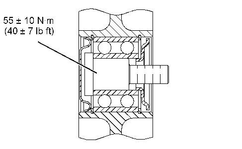
1. Use a breaker bar to release the tension on belt tensioner (1). Remove the drive belt.
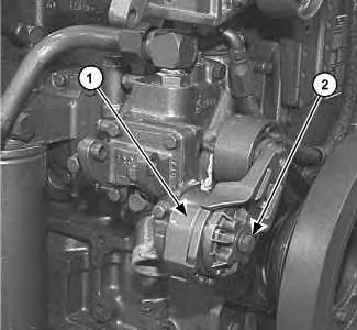
2. Remove bolt (2) and belt tensioner (1).
Installation Procedure
i01930316
Illustration 2
g01011962
1. Position belt tensioner (1) on the cylinder block. Install bolt (2).
2. Install the drive belt. Use a breaker bar to release tension on belt tensioner (1).
Previous Screen
Product: MOBILE HYD POWER UNIT
Model: 325C MOBILE HYD POWER UNIT MSG
Configuration: 325C Mobile Hydraulic Power Unit MSG00001-UP (MACHINE) POWERED BY 3126B Engine
Disassembly and Assembly
3126B Engines for Caterpillar Built Machines
Electronic Control Module - Remove and Install
SMCS - 1901-010
Removal Procedure
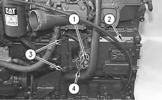
1. Remove the fuel lines from the fuel cooled ECM (if equipped).
Shutdown SIS
Illustration 1
Typical example
g00609591
2. Loosen screw (1) until wiring harness (4) can be disconnected. Disconnect wiring harness (4) from electronic control module (2).
3. Remove four bolts (3). Remove the electronic control module from the engine.
Installation Procedure
Suggest:
If the above button click is invalid.
Please download this document first, and then click the above link to download the complete manual.
Thank you so much for reading

Illustration 2
Typical example
g00609591
1. Position electronic control module (2) on the engine and install four bolts (3).
2. Connect wiring harness (4) to electronic control module (2). Tighten screw (1) to a torque of 6 ± 1 N·m (53 ± 9 lb in).
3. Reconnect the fuel lines to the fuel cooled ECM (if equipped).
1993 - 2020 Caterpillar Inc.