Shutdown SIS
Previous Screen
Product: EXCAVATOR
Model: 325B L EXCAVATOR 8RR
Configuration: 325B & 325B L TRACK-TYPE EXCAVATORS 8RR00001-UP (MACHINE) POWERED BY 3116 ENGINE
Disassembly and Assembly
325B Excavator Machine Systems
Final Drive - Assemble
SMCS - 4050-016
Assembly procedure
Note: Make sure that all of the parts of the final drive are thoroughly clean and free of dirt and debris prior to assembly.
1. Check the condition of all the O-ring seals that are used in the final drive. If any of the Oring seals are damaged, use new parts for replacement.
Note: If the final drive sprocket was removed from the main housing, refer to Disassembly and Assembly, "Final Drive Sprocket - Remove and Install" in this manual. Follow the installation procedure in order to install the final drive sprocket on the main housing.
2. Assemble the final drive on Tooling (A).
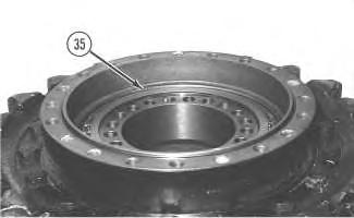
3. Apply Tooling (F) to the surfaces inside the main housing that contact bearings (38) and (39). Install bearings (38) and (39) in the original locations in the main housing with a press. Install bearings (38) and (39) until the bearings contact the counterbore in the main housing.
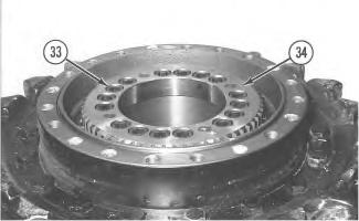
4. Use the following procedure to determine the correct bearing preload and the correct thickness of shims (35) that are used under gear (34).
 Illustration 1
g00511934
Illustration 2
g00511872
Illustration 3
g00511857
Illustration 1
g00511934
Illustration 2
g00511872
Illustration 3
g00511857
g00511882
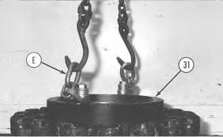
a. Fasten Tooling (E) and a suitable lifting device to main housing (31), as shown. Install main housing (31) on the motor housing.
b. Use a suitable press and a spacer to apply a load of 4000 kg (8820 lb) on bearing (38).
c. Rotate the main housing in order to seat the bearings.
d. Reduce the load on bearing (38) to 1000 ± 100 kg (2200 ± 220 lb).
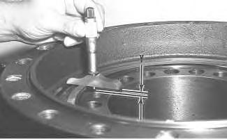
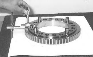
e. Maintain the load on bearing (38). Measure the distance between the top face of the motor housing and the bearing inner race. Use a depth micrometer to take this measurement in several locations around the bearing. Compute the average of the measured dimensions and record the number. Call this dimension (Y).
Illustration 4 Illustration 5 g00513387f. Use a depth micrometer and measure the distance between the hub face and the gear face of gear (34). Take measurements at several locations around the gear. Compute the average of the measured dimensions and record the number. Call this dimension (X).
g. Determine the correct thickness of the shim pack which is made up of shims (35). The shim pack is used between the motor housing and gear (34). Use the following equation to determine the shim pack thickness.
Shim pack thickness ... (X) − (Y) ± 0.05 mm (0.002 inch)
Note: If two shims are required, install the thinner shim next to gear (34) when the gear is installed.
5. Remove the main housing from the motor housing.
Note: The rubber seals and all surfaces that contact the seals must be clean and dry. After installation of the seals, apply clean SAE 30 oil on the contact surfaces of the metal seals. For more information concerning the assembly and installation of Conventional Duo-Cone Seals, refer to Disassembly and Assembly, "Duo-Cone Conventional Seals - Install" in this manual.
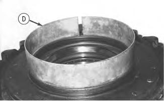 Illustration 6 g00513390
Illustration 7 g00513401
6. Install Duo-Cone seal (37) in the main housing with Tooling (D).
Illustration 6 g00513390
Illustration 7 g00513401
6. Install Duo-Cone seal (37) in the main housing with Tooling (D).
7. Use Tooling (D) in order to install Duo-Cone seal (36) in the motor.
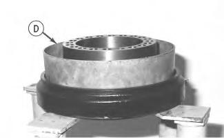
Note: Be sure that the Duo-Cone seals are not scratched or damaged during the assembly of the main housing or during the assembly of the motor housing. After installation of the main housing on the motor housing, there will be a small gap between the components. The gap is caused by the Duo-Cone seals. The gap will be eliminated during installation of gear (34).
8. Fasten Tooling (E) and a suitable lifting device to main housing (31). Position the main housing and the final drive sprocket on the motor housing. Make sure that the Duo-Cone seals are not scratched or damaged during installation.
Illustration 8
g00513424
Illustration 9
g00511882
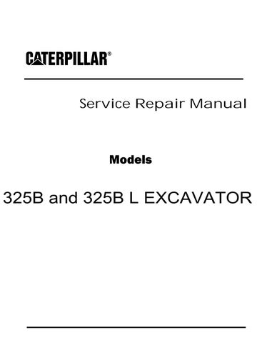
9. Apply Tooling (F) on the four pins in gear (34).
10. Place shim pack (35), which was determined in Step 4.a through 4.g, and gear (34) in the correct position on the motor housing. If two shims were required, put the thinner shim in contact with gear (34). Make sure that all of the holes in the components are in alignment with each other.
11. Apply Tooling (G) on the threads of socket head bolts (33). Install the socket head bolts (33) in order to hold gear (34) in place. Tighten bolts (33) evenly and tighten the bolts in diagonally opposite pairs.
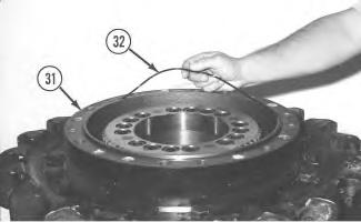 Illustration 10
g00511872
Illustration 11
g00511857
Illustration 10
g00511872
Illustration 11
g00511857
Illustration 12 g00511825
12. Install O-ring seal (32) in main housing (31).
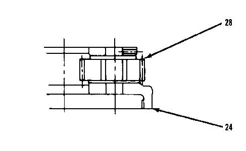
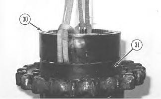
Illustration 13 g00511809
13. Thoroughly clean the mating surface of main housing (31) that contacts ring gear (30). Apply a bead of Tooling (H) on the mating surface of ring gear (30). Fasten a suitable lifting device to ring gear (30). Place ring gear (30) in position on the main housing. Make sure that the alignment mark on the main housing and the alignment mark on the ring gear line up with each other. It may be necessary to use a soft faced hammer to seat the ring gear on the main housing.
Illustration 14 g00513561Illustration 15
g00572382
Illustration 16
g00511799
14. Use the following procedure to assemble carrier assembly (24).
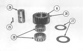
a. Apply clean SAE 30 oil on bearings (29). Install bearings (29) in planetary gear (28).
b. Install thrust washer (27) on each side of planetary gear (28).
c. Install planetary gear (28) and thrust washers (27) in carrier (24).
Note: If planetary gear (28) has oil grooves "N", make sure that the planetary gear's oil grooves are facing in the correct direction, which was noted during the disassembly of carrier assembly (24).
d. Install planetary shaft (26) in carrier (24) and through planetary gear (28). Make sure that the spring pin hole in the planetary shaft is in alignment with the spring pin hole in the carrier.
Illustration 17
g00513451
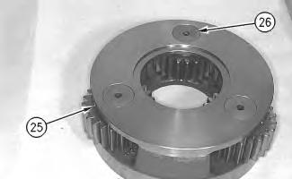
15. Install spring pin (25) in the carrier and into the planetary shaft. Install the spring pin until the spring pin is even with the outside surface of the carrier. Orient the split in the spring pin horizontally to the carrier. Align the split in the spring pin so that the split faces either side of the carrier, as shown.
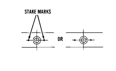
16. Make a stake mark on each side of the spring pin hole in the carrier. This will prevent the spring pin from falling out of the spring pin hole. Each stake mark should be approximately 1.5 mm (0.06 inch) from the outside diameter of the spring pin hole.
17. Repeat Steps 14 through 16 in order to install the remaining planetary gears in carrier (24).
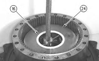
Illustration 18
g00511795
18. Install carrier assembly (24) in ring gear (30). Slide a piece of steel bar stock between the planetary gears in carrier assembly (24), as shown. Make sure that the bar stock is centered in the carrier assembly. Fasten a suitable lifting device to the steel bar stock, as shown. Position carrier assembly (24) in ring gear (30). It may be necessary to move carrier assembly (24) back and forth during installation in order to ensure that all gears align and all gears mesh properly. Make sure that the carrier assembly is seated properly.
19. Install spacer (16) in carrier assembly (24), as shown.
20. Use the following procedure to assemble carrier assembly (15).
a. Install sun gear (23) in carrier (15).
b. Use a screwdriver in order to install retaining ring (22) which secures sun gear (23) in the carrier.
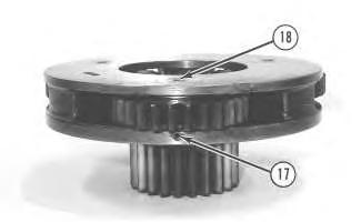
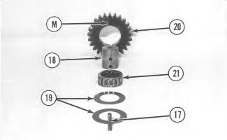
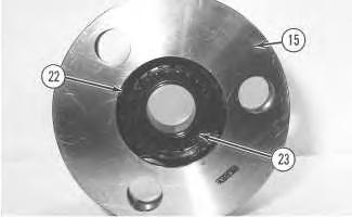 Illustration 19 g00511788
Illustration 20 g00572352
Illustration 21 g00511735
Illustration 19 g00511788
Illustration 20 g00572352
Illustration 21 g00511735
c. Apply clean SAE 30 oil on bearing (21). Install bearing (21) in planetary gear (20).
d. Install thrust washer (19) on each side of planetary gear (20).
e. Install planetary gear (20) and thrust washers (19) in carrier (15).
Note: If planetary gear (20) has oil grooves "M", make sure that the planetary gear's oil grooves are facing in the correct direction, which was noted during the disassembly of carrier assembly (15).
f. Install planetary shaft (18) in carrier (15) and through planetary gear (20). Make sure that the spring pin hole in the carrier is in alignment with the spring pin hole in the planetary shaft.
22 g00513451
21. Install spring pin (17) in the carrier and into the planetary shaft. Install the spring pin until the spring pin is even with the outside surface of the carrier. Orient the split in the spring pin horizontally to the carrier. Align the split in the spring pin so that the split faces either side of the carrier, as shown.
22. Make a stake mark on each side of the spring pin hole in the carrier. This will prevent the spring pin from falling out of the spring pin hole. Each stake mark should be approximately 1.5 mm (0.06 inch) from the outside diameter of the spring pin hole.
23. Repeat Steps 20 through 22 in order to install the remaining planetary gears in carrier (15).
24. Install carrier assembly (15) in carrier assembly (24). Move the carrier back and forth during the installation in order to ensure that all gears engage properly. Make sure that the carrier assembly is seated properly.
25. Install spacer (8) in the top side of carrier assembly (15).
Illustration25
Note: Make sure that retaining ring (9) is installed with the cross section of the ring in the position that is shown. Refer to Illustration 25.
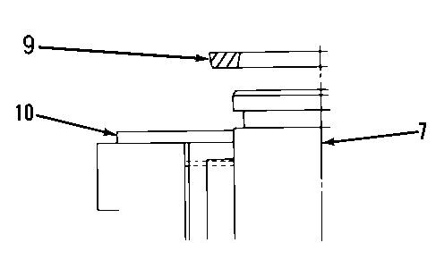
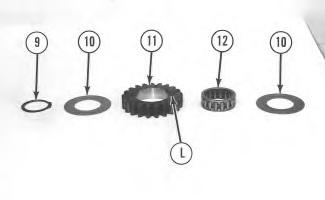
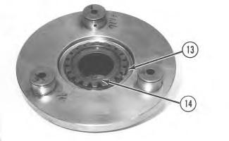 Illustration 23 g00511653
Illustration 24 g00572334
Illustration
g00513639
Illustration 23 g00511653
Illustration 24 g00572334
Illustration
g00513639
26. Use the following procedure to assemble carrier assembly (7).
a. Install sun gear (14) in carrier (7), as shown. Refer to Illustration 23.
b. Use a screwdriver in order to install retaining ring (13) which secures sun gear (14) in the carrier.
c. Apply clean SAE 30 oil on bearing (12). Install bearing (12) in planetary gear (11).
d. Install thrust washer (10) on each side of planetary gear (11).
e. Install planetary gear (11) and thrust washers (10) on the shaft of carrier (7).
Note: If planetary gear (11) has oil grooves "L", make sure that the planetary gear's oil grooves are facing in the same direction, which was noted during the disassembly of carrier assembly (7).
f. Use Tooling (C) in order to install retaining ring (9) that secures the planetary gear in position. Make sure that retaining ring (9) is installed correctly. Refer to Illustration 25.
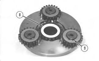
27. Repeat Step 26 in order to install the remaining planetary gears on carrier assembly (7).
Illustration 26
28. Install spacer (8) in carrier assembly (7).
g00511640
Illustration 27
g00511636
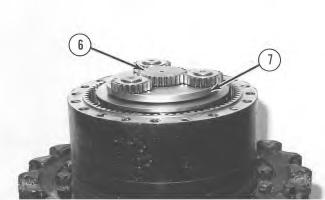
29. Install carrier assembly (7) in carrier assembly (15). Make sure that the carrier assembly is seated properly. Install sun gear (6) in carrier assembly (7).
30. Use a 25.4 mm (1.00 inch) thick straight edge and a depth micrometer in order to measure dimension (P). Dimension (P) is between the upper surface of sun gear (6) and the machined surface of ring gear (30). Record dimension (P).
31. Use a 25.4 mm (1.00 inch) thick straight edge and a depth micrometer in order to measure dimension (Q). Dimension (Q) is from the machined surface of cover (2) to the bottom of the insertion hole of thrust plate (5). Record dimension (Q).
Note: Thrust plate (5) is available in several thicknesses.
32. Determine the correct thickness of thrust plate (5). Use the following equation to determine the thrust plate thickness.
Thrust plate thickness ... (Q) − (P) − 1.0 mm (0.04 inch) to 2.0 mm (0.08 inch)
33. Use a plastic hammer in order to install the correct thickness of thrust plate (5) in cover (2).
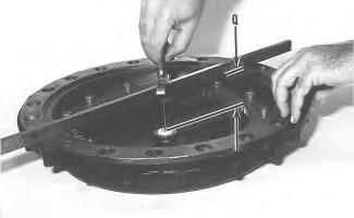
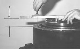 Illustration 28
g00513653
Illustration 29
g00513657
Illustration 28
g00513653
Illustration 29
g00513657
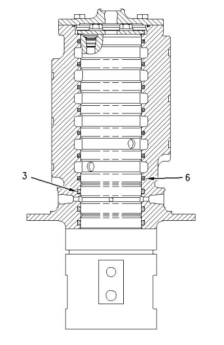
g00511631
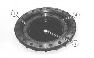
34. Put ring gear (4) in position in cover (2). Make sure that all of the mounting bolt holes in both components are in alignment with each other. Apply Tooling (G) on the threads of socket head bolts (3) that hold ring (4) in place. Install socket head bolts (3) and tighten socket head bolts (3) evenly.
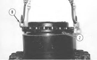
35. Make sure that the machined surface of ring gear (30) is thoroughly clean and dry and that the machined surface is free of dirt and debris. Apply a bead of Tooling (H) around the machined surface of the ring gear. Fasten Tooling (B) and a suitable lifting device to cover (2). Place the cover in the original position on the ring gear. It will be necessary to rotate the cover back and forth in order to engage the planetary gears of carrier assembly (7) with the ring gear in cover (2).
36. Apply Tooling (G) on the threads of bolts (1) that hold cover (2) in position. Install the washers and bolts (1). Tighten bolts (1) evenly to a torque of 530 ± 70 N·m (390 ± 50 lb ft).
End By:
a. Install the final drive. Refer to Disassembly and Assembly, "Final Drive - Install".
Copyright 1993 - 2020 Caterpillar Inc.
Rights Reserved.
Network For SIS Licensees.
Illustration 30 Illustration 31 g00511600Shutdown SIS
Previous Screen
Product: EXCAVATOR
Model: 325B L EXCAVATOR 8RR
Configuration: 325B & 325B L TRACK-TYPE EXCAVATORS 8RR00001-UP (MACHINE) POWERED BY 3116 ENGINE
Disassembly and Assembly
325B Excavator Machine Systems Media
Final Drive - Install
SMCS - 4050-012
Installation Procedure
Table 1
Required Tools
Tool Part Number Part Description Qty
(A) 138-7574 Link Bracket 2
1. Install the travel motor in the final drive. Refer to Disassembly and Assembly, "Travel Motor - Install" in this manual.
2. Make sure that the mating surfaces of the final drive and the undercarriage frame assembly are thoroughly clean and free of dirt and debris prior to assembly.
3. Fasten Tooling (A) and a hoist to final drive (7). Carefully, place the final drive in position on the undercarriage frame assembly.
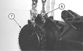
Illustration 2
g00486988
4. Apply 9S-3263 Thread Lock Compound on the threads of 20 bolts (8). Install 20 bolts (8) that secure the final drive to the undercarriage frame assembly. Tighten the bolts evenly.
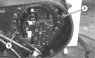
5. Install two plugs (9) in the forcing bolt holes that are located in the undercarriage frame assembly.
NOTICE
Care must be taken to ensure that fluids are contained during performance of inspection, maintenance, testing, adjusting, and repair of the product. Be prepared to collect the fluid with suitable containers before opening any compartment or disassembling any component containing fluids.
Refer to Special Publication, NENG2500, "Dealer Service Tool Catalog" for tools and supplies suitable to collect and contain fluids on Cat® products.
Dispose of all fluids according to local regulations and mandates.
Illustration 3
g00486981
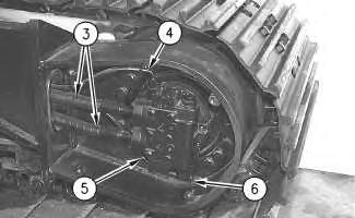
6. Install the O-ring seal on elbow (6). Install the elbow in the travel motor. Tighten the elbow to a torque of 40 ± 5 N·m (30 ± 4 lb ft). Make sure that the elbow is oriented properly.
7. Remove the plugs from the ends of two hose assemblies (4) and (5). Check the condition of the O-ring seals that are used in the ends of two hose assemblies (4) and (5). If the O-ring seals are damaged, use new parts for replacement.
8. Connect two hose assemblies (4) and (5) to the travel motor.
9. Remove the plugs from the ends of two tube assemblies (3). Check the condition of the Oring seals that are used in the ends of two tube assemblies (3). If the O-ring seals are damaged, use new parts for replacement.
10. Connect two tube assemblies (3) to the travel brake valve.
11. Check the oil level in the hydraulic oil tank. If necessary, fill the hydraulic oil tank with oil to the correct level. Refer to Operation and Maintenance Manual, "Lubricant Viscosities" for the proper oil viscosity and Operation and Maintenance Manual, "Hydraulic System Oil Level - Check" for the correct filling procedure.
12. Start the engine, and check the final drive for oil leaks. Stop the engine. Illustration
g00486980
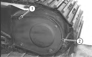
13. Install cover assembly (2). Install the washers and four bolts (1) that secure cover assembly (2) to the inside rear of the undercarriage frame assembly. Tighten four bolts (1) to a torque of 130 ± 10 N·m (95 ± 7 lb ft).
End By:
a. Connect the track assembly. Refer to Disassembly and Assembly, "Track - Connect" in this manual.
Copyright 1993 - 2020 Caterpillar Inc. All Rights Reserved.
Shutdown SIS
Previous Screen
Product: EXCAVATOR
Model: 325B L EXCAVATOR 8RR
Configuration: 325B & 325B L TRACK-TYPE EXCAVATORS 8RR00001-UP (MACHINE) POWERED BY 3116 ENGINE
Disassembly and Assembly
325B Excavator Machine Systems
Swivel - Remove
SMCS - 5060-011
Removal Procedure
Table 1
Required Tools
(A) 138-7573 Link Bracket 1
NOTICE
Care must be taken to ensure that fluids are contained during performance of inspection, maintenance, testing, adjusting and repair of the product. Be prepared to collect the fluid with suitable containers before opening any compartment or disassembling any component containing fluids.
Refer to Special Publication, NENG2500, "Caterpillar Dealer Service Tool Catalog" for tools and supplies suitable to collect and contain fluids on Caterpillar products.
Dispose of all fluids according to local regulations and mandates.
At operating temperature the implement hydraulic oil tank is hot and under pressure. Hot oil can cause burns.
To prevent possible injury, release the pressure in the implement hydraulic system before hydraulic lines or components are disconnected or removed.
1. Release the hydraulic system pressure. Refer to Disassembly and Assembly, "Hydraulic System Pressure - Release" in this manual.
2. Clean the outside of the swivel joint and the area around the swivel joint prior to removal.
Illustration 1
g00513210
3. Oil will drain from all hose assemblies that are connected to the swivel joint. Place suitable containers under the machine in the area of the swivel joint in order to collect the oil.
4. Put identification marks on seven hose assemblies (1) for installation purposes. Disconnect seven hose assemblies (1) from the swivel joint. Put plugs in the ends of the hose assemblies in order to prevent oil loss and keep contaminants out of the hydraulic system.
5. Remove two bolts (2) and the washers that hold setting plate (3) in position. Remove setting plate (3).
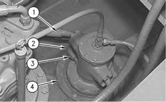
6. Remove eight bolts (4).
7. Remove one cover bolt from the swivel joint. Reuse the cover bolt in order to fasten Tool (A) to the swivel joint. Fasten a hoist to Tool (A).
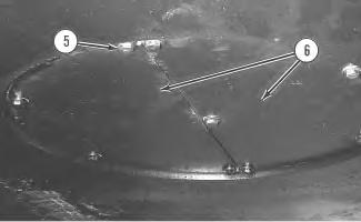
Illustration 2
This view is from the underside of the machine.
g00513213
8. Remove bolts (5) and two cover assemblies (6) from the underside of the undercarriage frame assembly.
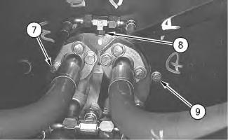
Illustration 3
This view is from the underside of the machine.
g00513219
9. Put identification marks on eight hose assemblies (7) for installation purposes. Disconnect eight hose assemblies (7) from the bottom of the swivel joint. Put plugs in the ends of the hose assemblies in order to prevent oil loss and keep contaminants out of the hydraulic system.
10. Remove tee fitting (8) from the swivel joint.
11. Cover the ports in the bottom of the swivel joint with tape in order to keep dirt and debris out of the unit.
12. Remove six bolts (9).
13. Remove the swivel joint from the machine. The weight of the swivel joint is 43 kg (95 lb).
Shutdown SIS
Previous Screen
Product: EXCAVATOR
Model: 325B L EXCAVATOR 8RR
Configuration: 325B & 325B L TRACK-TYPE EXCAVATORS 8RR00001-UP (MACHINE) POWERED BY 3116 ENGINE
Disassembly and Assembly
325B Excavator Machine Systems
Swivel - Disassemble
SMCS - 5060-015
Disassembly Procedure
Start By:
a. Remove the swivel joint. Refer to Disassembly and Assembly, "Swivel - Remove".
NOTICE
Care must be taken to ensure that fluids are contained during performance of inspection, maintenance, testing, adjusting and repair of the product. Be prepared to collect the fluid with suitable containers before opening any compartment or disassembling any component containing fluids.
Refer to Special Publication, NENG2500, "Caterpillar Dealer Service Tool Catalog" for tools and supplies suitable to collect and contain fluids on Caterpillar products.
Dispose of all fluids according to local regulations and mandates.
1. Thoroughly clean the outside of the swivel joint prior to disassembly.
2. Remove bolts (1) and cover (2) from outside housing (8). Remove O-ring seal (4) from outside housing (8).
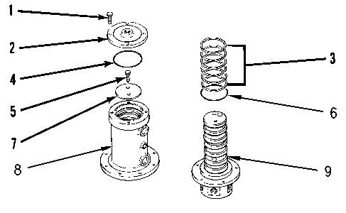
3. Remove bolts (5) and retainer (7) from rotor (9). Remove outside housing (8) from rotor (9).
4. Turn the outside housing upside-down and remove O-ring seals (6) and seals (3) from the outside housing.
Shutdown SIS
Previous Screen
Product: EXCAVATOR
Model: 325B L EXCAVATOR 8RR
Configuration: 325B & 325B L TRACK-TYPE EXCAVATORS 8RR00001-UP (MACHINE) POWERED BY 3116 ENGINE
Disassembly and Assembly
325B Excavator Machine Systems
Swivel - Assemble
SMCS - 5060-016
Assembly Procedure
1. Make sure that all of the parts of the swivel joint are thoroughly clean and free of dirt and debris.
Illustration 1 g00879932
2. Check the condition of seals (3) and O-ring seals (6). If the seals or O-ring seals are worn or damaged, use new parts for replacement.
Suggest:
If the above button click is invalid.
Please download this document first, and then click the above link to download the complete manual.
Thank you so much for reading

Illustration 2
The number of seals may vary.
g00917800
3. Install seals (3) and O-ring seals (6) in outside housing (8). Put clean hydraulic oil on seals (3) and O-ring seals (6).
4. Install outside housing (8) over rotor (9). Install retainer (7) and bolts (5) that secure the retainer.
5. Check the condition of O-ring seal (4). If the O-ring seal is damaged, use a new part for replacement.
6. Apply clean hydraulic oil on O-ring seal (4). Install the O-ring seal in the outside housing.
7. Install cover (2) and bolts (1) that secure the cover.