Shutdown SIS
Previous Screen
Product: EXCAVATOR
Model: 325-A EXCAVATOR 9ZK
Configuration: 325, 325 L AND 325 LN EXCAVATORS 9ZK00001-UP (MACHINE) POWERED BY 3116 ENGINE
Disassembly and Assembly
446 and 446B Backhoe Loaders, Lexion 450 Combine, 3114 and 3116 Engines, IT18F Integrated Toolcarrier, D6M Track-Type Tractor and 928F, 950F and 950G
Wheel Loaders
Inlet Manifold - Install
SMCS - 1058-012
Installation Procedure
NOTICE
Keep all parts clean from contaminants.
Contaminants may cause rapid wear and shortened component life.
NOTICE
Care must be taken to ensure that fluids are contained during performance of inspection, maintenance, testing, adjusting, and repair of the product. Be prepared to collect the fluid with suitable containers before opening any compartment or disassembling any component containing fluids.
Refer to Special Publication, NENG2500, "Dealer Service Tool Catalog" for tools and supplies suitable to collect and contain fluids on Cat products.
Dispose of all fluids according to local regulations and mandates.
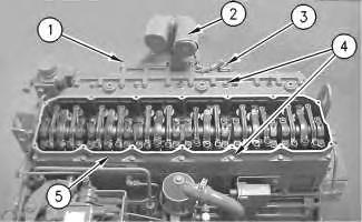
Illustration 1
g00675794
1. Install a new gasket (6) on the cylinder head.
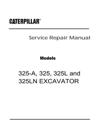
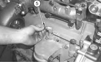
Illustration 2
g00629952
2. Position the air inlet manifold (5) on the engine.
3. Install bolts (4). Tighten the bolts to a torque of 28 ± 7 N·m (21 ± 5 lb ft).
4. Install air inlet elbows (2) on air inlet manifold (5).
5. Install bolts (1) and connect air inlet heater solenoid (3).
End By:
a. Install the valve mechanism cover. Refer to Disassembly and Assembly, "Valve Mechanism Cover - Remove and Install".
Copyright 1993 - 2020 Caterpillar Inc. All Rights Reserved. Private Network For SIS Licensees.
Sat Aug 8 22:55:25 UTC+0800 2020
Shutdown SIS
Previous Screen
Product: EXCAVATOR
Model: 325-A EXCAVATOR 9ZK
Configuration: 325, 325 L AND 325 LN EXCAVATORS 9ZK00001-UP (MACHINE) POWERED BY 3116 ENGINE
Disassembly and Assembly
446 and 446B Backhoe Loaders, Lexion 450 Combine, 3114 and 3116 Engines, IT18F Integrated Toolcarrier, D6M Track-Type Tractor and 928F, 950F and 950G
Wheel Loaders
Inlet and Exhaust Valves - Remove and Install
SMCS - 1105-010
Removal Procedure
Table 1
Required Tools
Tool Part Number Part Description Qty
A 5S-1330 Valve Spring Compressor 1
Start By:
a. Remove the cylinder head assembly. Refer to Disassembly and Assembly, "Cylinder HeadRemove".
NOTICE
Keep all parts clean from contaminants.
Contaminants may cause rapid wear and shortened component life.
Note: For information on the reusability of the inlet valves, the exhaust valves and the springs, refer to Guideline For Reusable Parts And Salvage Operations, SEBF8002, "Valves, Valve Springs, Valve Rotators, and Locks", Guideline For Reusable Parts And Salvage Operations, SEBF8034, "Valve and Valve Spring Specifications", and Guideline For Reusable Parts And Salvage Operations, SEBF8162, "Specifications to Measure and Salvage Cylinder Head Assemblies and Related Components".
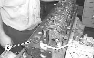
Note: The following components of the exhaust valves are different from the components of the inlet valves: spring retainer (2), valve spring (3) and valve (5).
1. Use Tooling (A) to compress valve spring (3). Remove retainer lock (1).
2. Remove Tooling (A).
3. Remove spring retainer (2). Remove valve spring (3).
Illustration 1 g01011225 Illustration 2 g010112694. Remove valve seal (4) and valve (5).
5. Repeat Steps 1 through 4 in order to remove the remaining inlet valves and exhaust valves.
Installation Procedure
Table 2
Required
A 5S-1330 Valve Spring Compressor 1
NOTICE
Keep all parts clean from contaminants. Contaminants may cause rapid wear and shortened component life.
Note: For information on the reusability of the inlet valves, the exhaust valves and the springs, refer to Guideline For Reusable Parts And Salvage Operations, SEBF8002, "Valves, Valve Springs, Valve Rotators, and Locks", Guideline For Reusable Parts And Salvage Operations, SEBF8034, "Valve and Valve Spring Specifications", and Guideline For Reusable Parts And Salvage Operations, SEBF8162, "Specifications to Measure and Salvage Cylinder Head Assemblies and Related Components".
Illustration 3
g01011225
1. Lubricate valve (5) with clean engine oil. Install valve (5) in the cylinder head assembly. Install new valve seal (4) against the valve guide.
2. Place the following items on the valve stem: valve spring (3) and spring retainer (2).
The valve keepers can be thrown from the valve when the valve spring compressor is released. Ensure that the valve keepers are properly installed on the valve stem. To help prevent personal injury, keep away from the front of the valve keepers and valve springs during the installation of the valves.
Note: A small amount of grease can be used to hold retainer locks (1) in position during installation.
3. Use Tooling (A) to compress valve spring (3). Install retainer lock (1).
4. Repeat Steps 1 through 3 in order to install the remaining inlet valves and exhaust valves.
End By:
a. Install the cylinder head assembly. Refer to Disassembly and Assembly, "Cylinder HeadInstall".
Shutdown SIS
Previous Screen
Product: EXCAVATOR
Model: 325-A EXCAVATOR 9ZK
Configuration: 325, 325 L AND 325 LN EXCAVATORS 9ZK00001-UP (MACHINE) POWERED BY 3116 ENGINE
Disassembly and Assembly
446 and 446B Backhoe Loaders, Lexion 450 Combine, 3114 and 3116 Engines, IT18F Integrated Toolcarrier, D6M Track-Type Tractor and 928F, 950F and 950G
Wheel Loaders
Inlet and Exhaust Valve Guides - Remove and Install
SMCS - 1104-010
Removal Procedure
Table 1
Required Tools
Tool Part Number Part Description Qty
A 1U-7793 Valve Guide Driver (1) 1
( 1 ) Part of 1U-6685 Valve Guide Tool Kit
Start By:
A. Remove the inlet and exhaust valves. Refer to Disassembly and Assembly, "Inlet and Exhaust Valves - Remove and Install".
NOTICE
Keep all parts clean from contaminants.
Contaminants may cause rapid wear and shortened component life.
Note: For information on the reusability of the valve guides, refer to Guideline For Reusable Parts And Salvage Operations, SEBF8218, "Specifications for Cylinder Head Asseblies 3114, 3116, and 3126 Engines" and Guideline For Reusable Parts And Salvage Operations, SEBF8162, "Procedure to Measure and Salvage Cylinder Head Assemblies and Related Components".
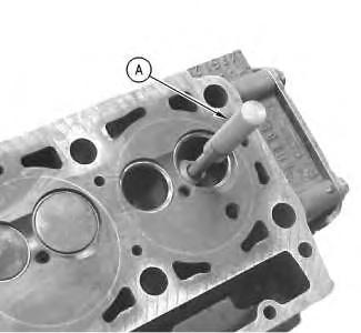
Illustration
Typical example
g00745735
1. Use Tooling (A) to remove the inlet valve guides from the cylinder head assembly. Use Tooling (A) to remove the exhaust valve guides from the cylinder head assembly.
Installation Procedure
Table 2 Required Tools
NOTICE
Keep all parts clean from contaminants.
Contaminants may cause rapid wear and shortened component life.
Note: For information on the reusability of the valve guides, refer to Guideline For Reusable Parts And Salvage Operations, SEBF8218, "Specifications for Cylinder Head Assemblies 3114, 3116, and 3126 Engines" and Guideline For Reusable Parts And Salvage Operations, SEBF8162, "Procedure to Measure and Salvage Cylinder Head Assemblies and Related Components".
Typical example
1. Position inlet valve guide (1) and tap on the top of inlet valve guide (1). This is done in order to start inlet valve guide (1) into the cylinder head assembly.
2. Use Tooling (A) and Tooling (B) to install inlet valve guide (1). Install inlet valve guides (1) until tooling (B) contacts the cylinder head.
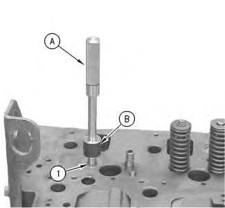 Illustration 2
g00745782
Illustration 2
g00745782
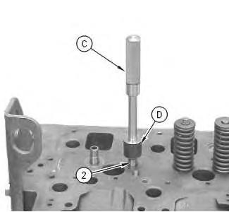
Illustration 3
Typical example
g00745672
3. Position exhaust valve guide (2) and tap on the top of exhaust valve guide (2). This is done in order to start the exhaust valve guide into the cylinder head assembly.
Note: Some of the early engines have inlet valves and exhaust valves that are identical in size. Use the same specifications and the same tools for both valves. Proceed to Step 4 if the valves are not the same size.
4. Use Tooling (C) and Tooling (D) to install exhaust valve guide (2). Install inlet valve guides (2) until tooling (D) contacts the cylinder head.
End By: Install the inlet and exhaust valves. Refer to Disassembly and Assembly, "Inlet and Exhaust Valves - Remove and Install".
Copyright 1993 - 2020 Caterpillar Inc.
All Rights Reserved.
Private Network For SIS Licensees.
Sat Aug 8 22:57:16 UTC+0800 2020
Shutdown SIS
Previous Screen
Product: EXCAVATOR
Model: 325-A EXCAVATOR 9ZK
Configuration: 325, 325 L AND 325 LN EXCAVATORS 9ZK00001-UP (MACHINE) POWERED BY 3116 ENGINE
Disassembly and Assembly
446 and 446B Backhoe Loaders, Lexion 450 Combine, 3114 and 3116 Engines, IT18F Integrated Toolcarrier, D6M Track-Type Tractor and 928F, 950F and 950G
Wheel Loaders
Inlet and Exhaust Valve Seat Inserts - Remove and Install
SMCS - 1103-010
Removal Procedure Table 1
Required Tools
(1)
Start By:
a. Remove the inlet and exhaust valves. Refer to Disassembly and Assembly, "Inlet and Exhaust Valves - Remove and Install".
NOTICE
Keep all parts clean from contaminants.
Contaminants may cause rapid wear and shortened component life.
Note: For information on the reusability of the valve seats, refer to Guideline For Reusable Parts And Salvage Operations, SEBF8218, "Specifications for Cylinder Head Assemblies 3114, 3116, and 3126 Engines".
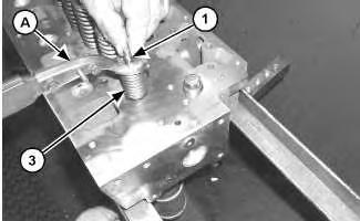
g00615519
g00656459
Note: Replace Tooling (A) with Tooling (B) for the removal of the inlet valve seat insert.
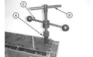
1. Install Tooling (A) in the exhaust valve seat insert.
2. Install Tooling (C) and Tooling (D) in Tooling (A). Hand tighten Tooling (D). Tooling (A) will expand below the edge of valve seat insert (1).
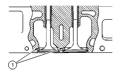 Illustration 1
Illustration 2
Illustration 1
Illustration 2
Illustration 3
g00656462
3. Install Tooling (E) on the cylinder head under Tooling (C). Hold Tooling (D) while you turn Tooling (C). Remove valve seat insert (1).
Installation
NOTICE
Keep all parts clean from contaminants.
Contaminants may cause rapid wear and shortened component life.
Note: For information on the reusability of the valve seats, refer to Guideline For Reusable Parts And Salvage Operations, SEBF8218, "Specifications for Cylinder Head Assemblies 3114, 3116, and 3126 Engines".
1. Cool the valve seat inserts for easier installation.
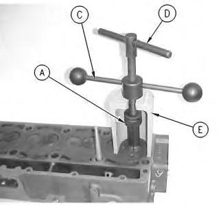
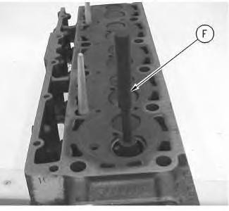
Illustration 4
g01003799
2. Turn Tooling (F) upside-down and use Tooling (F) and a press to install the valve seat inserts in the cylinder head assembly.
3. After the valve seat inserts are installed, grind the inserts to the final specification. Refer to Guideline for Reusable Parts and Salvage Operation, SEBF8218, "Specifications for Cylinder Head Assemblies 3114, 3116, and 3126 Engines" for the specifications.
End By:
a. Install the inlet valves and exhaust valves. Refer to Disassembly and Assembly, "Inlet and Exhaust Valves - Remove and Install".
Shutdown SIS
Previous Screen
Product: EXCAVATOR
Model: 325-A EXCAVATOR 9ZK
Configuration: 325, 325 L AND 325 LN EXCAVATORS 9ZK00001-UP (MACHINE) POWERED BY 3116 ENGINE
Disassembly and Assembly
446 and 446B Backhoe Loaders, Lexion 450 Combine, 3114 and 3116 Engines, IT18F Integrated Toolcarrier, D6M Track-Type Tractor and 928F, 950F and 950G
Wheel Loaders
Engine Oil Filter Base - Remove
SMCS - 1306-011
Removal Procedure
Table 1
Required Tools
Tool Part Number Part Description Qty
A 185-3630 Strap Wrench 1
Start By:
a. Remove the turbocharger. Refer to Disassembly and Assembly, "Turbocharger - Remove".
NOTICE
Keep all parts clean from contaminants.
Contaminants may cause rapid wear and shortened component life.
NOTICE
Care must be taken to ensure that fluids are contained during performance of inspection, maintenance, testing, adjusting, and repair of the product. Be prepared to collect the fluid with suitable containers
before opening any compartment or disassembling any component containing fluids.
Refer to Special Publication, NENG2500, "Dealer Service Tool Catalog" for tools and supplies suitable to collect and contain fluids on Cat products.
Dispose of all fluids according to local regulations and mandates.
1. Use Tooling (A) to remove engine oil filter (3).
2. Disconnect the tube assembly for the turbocharger inlet (1) from the engine oil filter base (4).
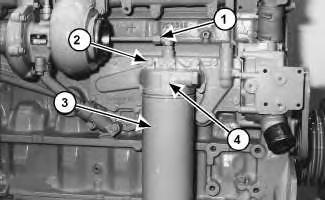
3. Remove bolts (2) and the washers that hold engine oil filter base (4) to the cylinder block.
4. Remove engine oil filter base (4) and the gasket.
Copyright 1993 - 2020 Caterpillar Inc. All Rights Reserved. Private Network For SIS Licensees.
Sat Aug 8 22:59:08 UTC+0800 2020
Illustration 1 g01009468Shutdown SIS
Previous Screen
Product: EXCAVATOR
Model: 325-A EXCAVATOR 9ZK
Configuration: 325, 325 L AND 325 LN EXCAVATORS 9ZK00001-UP (MACHINE) POWERED BY 3116 ENGINE
Disassembly and Assembly
446 and 446B Backhoe Loaders, Lexion 450 Combine, 3114 and 3116 Engines, IT18F Integrated Toolcarrier, D6M Track-Type Tractor and 928F, 950F and 950G
Wheel Loaders
Engine Oil Filter Base - Disassemble
SMCS - 1306-015
Disassembly Procedure
Start By:
a. Remove the engine oil filter base. Refer to Disassembly and Assembly, "Engine Oil Filter Base - Remove".
Make sure to wear all necessary protective equipment.
Follow the recommended procedure and use all recommended tooling to release the spring force.
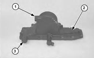
1. Remove plugs (1) and (3) from oil filter base (2).
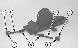
Illustration 2
g01011627
2. Remove springs (4) and valves (6). Remove O-ring seals (5) from plugs (1) and (3). Inspect the parts for wear or damage. If the parts are worn or damaged, use new parts for replacement.
Shutdown SIS
Previous Screen
Product: EXCAVATOR
Model: 325-A EXCAVATOR 9ZK
Configuration: 325, 325 L AND 325 LN EXCAVATORS 9ZK00001-UP (MACHINE) POWERED BY 3116 ENGINE
Disassembly and Assembly
446 and 446B Backhoe Loaders, Lexion 450 Combine, 3114 and 3116 Engines, IT18F Integrated Toolcarrier, D6M Track-Type Tractor and 928F, 950F and 950G
Wheel Loaders
Engine Oil Filter Base - Assemble
SMCS - 1306-016
Assembly Procedure
Illustration 1
g01011627
1. Install O-ring seals (5) onto plugs (1) and (3). Install valves (6) and springs (4).
Improper assembly of parts that are spring loaded can cause bodily injury.
To prevent possible injury, follow the established assembly procedure and wear protective equipment.
2. Install plugs (1) and (3) onto oil filter base (2).
End By:
a. Install the engine oil filter base. Refer to Disassembly and Assembly, "Engine Oil Filter Base - Install".
Shutdown SIS
Previous Screen
Product: EXCAVATOR
Model: 325-A EXCAVATOR 9ZK
Configuration: 325, 325 L AND 325 LN EXCAVATORS 9ZK00001-UP (MACHINE) POWERED BY 3116 ENGINE
Disassembly and Assembly
446 and 446B Backhoe Loaders, Lexion 450 Combine, 3114 and 3116 Engines, IT18F Integrated Toolcarrier, D6M Track-Type Tractor and 928F, 950F and 950G
Wheel Loaders
Engine Oil Filter Base - Install
SMCS - 1306-012
Installation Procedure
NOTICE
Keep all parts clean from contaminants.
Contaminants may cause rapid wear and shortened component life.
1. Position the gasket and engine oil filter base (4) on the cylinder block.
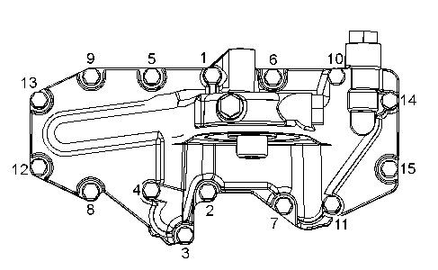
2. Install the washers and bolts (2) that hold engine oil filter base (4) to the cylinder block. Tighten the bolts according to the following procedure:
a. Tighten Bolt (1) through Bolt (15) in a numerical sequence to a torque of 15 N·m (11 lb ft).
b. Tighten Bolt (1) through Bolt (15) in a numerical sequence to a torque of 28 N·m (21 lb ft).
3. Apply lubricant to new O-ring seal (5) . Install O-ring seal (5) in the fitting on the engine oil filter base.
4. Connect tube assembly (1) to engine oil filter base (4) .
Note: Never install an oil filter with a wrench. Follow the instructions on the oil filter.
Illustration 2 g01185803 Illustration 3 g006767915. Put a coat of fresh oil on the O-ring seal for the engine oil filter. Install engine oil filter (3) on engine oil filter base (4) by hand.
6. After the O-ring seal contacts engine oil filter base (4) , turn engine oil filter (3) for 3/4 of a turn.
End By: Install the turbocharger. Refer to Disassembly and Assembly, "Turbocharger - Install".
Copyright 1993 - 2020 Caterpillar Inc. All Rights Reserved. Private Network For SIS Licensees.
Sat Aug 8 23:01:55 UTC+0800 2020
Suggest:
If the above button click is invalid.
Please download this document first, and then click the above link to download the complete manual.
Thank you so much for reading

Shutdown SIS
Previous Screen
Product: EXCAVATOR
Model: 325-A EXCAVATOR 9ZK
Configuration: 325, 325 L AND 325 LN EXCAVATORS 9ZK00001-UP (MACHINE) POWERED BY 3116 ENGINE
Disassembly and Assembly
446 and 446B Backhoe Loaders, Lexion 450 Combine, 3114 and 3116 Engines, IT18F Integrated Toolcarrier, D6M Track-Type Tractor and 928F, 950F and 950G
Wheel Loaders
Engine Oil Filter Bypass Valve - Remove and Install
SMCS - 1308-010-BV
Removal Procedure
NOTICE
Keep all parts clean from contaminants.
Contaminants may cause rapid wear and shortened component life.
NOTICE
Care must be taken to ensure that fluids are contained during performance of inspection, maintenance, testing, adjusting, and repair of the product. Be prepared to collect the fluid with suitable containers before opening any compartment or disassembling any component containing fluids.
Refer to Special Publication, NENG2500, "Dealer Service Tool Catalog" for tools and supplies suitable to collect and contain fluids on Cat products.
Dispose of all fluids according to local regulations and mandates.