Previous Screen
Product: EXCAVATOR
Model: 325-A EXCAVATOR 7TG
Configuration: 325, 325L EXCAVATOR 7TG00001-UP (MACHINE)
Disassembly and Assembly
325, 325B and 325L Excavators
Travel Motor - Disassemble
SMCS - 4351-015
Disassembly Procedure For The Travel Motor On CIPI
Undercarriage Arrangements Which Are Based On 325 Track Type Excavators
Start By:
A. Remove the travel motor. Refer to Disassembly and Assembly, "Travel Motor - Remove" in this manual.
NOTICE
Care must be taken to ensure that fluids are contained during performance of inspection, maintenance, testing, adjusting and repair of the product. Be prepared to collect the fluid with suitable containers before opening any compartment or disassembling any component containing fluids.
Refer to Special Publication, NENG2500, "Caterpillar Tools and Shop Products Guide" for tools and supplies suitable to collect and contain fluids on Caterpillar products.
Dispose of all fluids according to local regulations and mandates.
1. Thoroughly clean the outside of the travel motor prior to disassembly. Fasten the travel motor to a suitable holding fixture in a vertical position. The weight of the travel motor is approximately 71 kg (157 lb).
2. Put an alignment mark across the head and the body of the travel motor for assembly purposes. The head must be reinstalled in the head's original position on the travel motor body.
3. Remove nine socket head bolts (1) and head (2) from the travel motor body.
Note: During the removal of head (2) from the travel motor body, be careful not to damage the mating surfaces of the components.
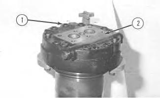 Illustration 1
g00510326
Illustration 2
g00510341
Illustration 1
g00510326
Illustration 2
g00510341
Illustration 3
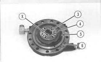
4. Turn over head (2). Remove O-ring seal (6), shims (5), port plate (4), and bearing (3) from the head. Remove the two check valve assemblies from the head.
Note: There is a retainer that is located under spring (9). This retainer is a press fit in head (2). Do not remove the retainer.
5. Insert a dowel rod with a small diameter into hole "X". Tap the dowel rod with a plastic hammer in order to remove spring (9), poppet (8) and seat (7) from the head.
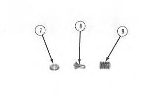
Illustration 4 g00510351
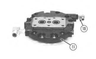
6. Remove three fittings (10) and four plugs (11) from the head. Remove the O-ring seal from each fitting.
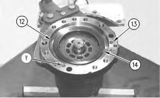
7. Remove three O-ring seals (12) and washer set (13) from the body of the travel motor.
8. Place a shop towel over brake piston (14). Retain brake piston (14) by hand, and apply approximately 525 kPa (75 psi) of shop air pressure to brake release port "Y". Make sure that the shop air pressure is free of water. Brake piston (14) will move up the piston guide, and out of the piston guide. Remove brake piston (14) from the travel motor body.

9. Remove O-ring seals (15) and (17), and backup rings (16) and (18) from the brake piston.
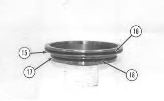 Illustration 5
g00510352
Illustration 6
g00510353
Illustration 5
g00510352
Illustration 6
g00510353
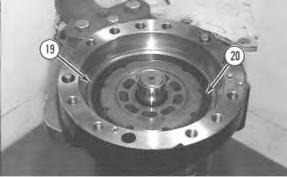
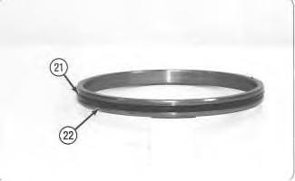
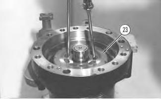 Illustration 7
g00510356
10. Remove piston guide (19), three friction plates and three steel plates (20) from the travel motor body.
Illustration 8
g00510359
11. Remove O-ring seal (21) and backup ring (22) from the piston guide.
Illustration 9
g00510365
Illustration 7
g00510356
10. Remove piston guide (19), three friction plates and three steel plates (20) from the travel motor body.
Illustration 8
g00510359
11. Remove O-ring seal (21) and backup ring (22) from the piston guide.
Illustration 9
g00510365
Note: Do not allow the components of barrel assembly (23) to come apart during the removal from the travel motor. All of the components in the barrel assembly must be reinstalled in the component's original location.
12. Use two large screwdrivers and slowly remove barrel assembly (23) from the travel motor body, as shown. Do not allow the components to fall apart.
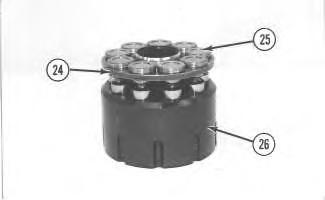
Illustration 10
13. Shoe retainer (24) and piston shoe assemblies (25) are nonserviceable separately. Prior to the removal of the shoe retainer and the piston shoe assemblies from barrel (26), put identification marks on piston shoe assemblies (25) for assembly purposes. Identification marks are used to identify the piston shoe assembly's location in shoe retainer (24) and barrel (26). The piston shoe assemblies must be reinstalled in the piston shoe assembly's original bores in the shoe retainer and the barrel.
14. Remove shoe retainer (24) and piston shoe assemblies (25) from barrel (26). Separate the piston shoe assemblies from the shoe retainer.
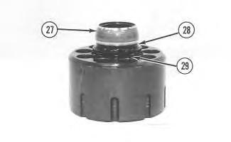
Illustration 11 g00510504
15. Remove guide (27), spacer (28) and nine springs (29) from the barrel.
Illustration 12 g00510547
Illustration 13 g00919084
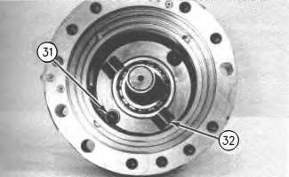
 16. Remove cam plate (30) from the travel motor body.
17. Put identification marks on two balls (31) and two keys (32) in the travel motor body for assembly purposes. Remove two balls (31) and two keys (32) from the travel motor body.
16. Remove cam plate (30) from the travel motor body.
17. Put identification marks on two balls (31) and two keys (32) in the travel motor body for assembly purposes. Remove two balls (31) and two keys (32) from the travel motor body.
Illustration 14 g00510551
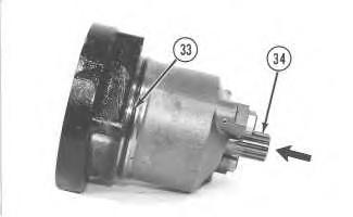
18. Remove O-ring seal (33) from the travel motor body.
19. Use a soft faced hammer to remove shaft assembly (34) from the travel motor body. Remove the shaft assembly in the direction that is indicated by the arrow. Refer to Illustration 33.
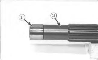
Illustration 15 g00510595
20. Remove retaining rings (35) from each side of bearing (36). Push shaft (34) out of bearing (36) with a press.
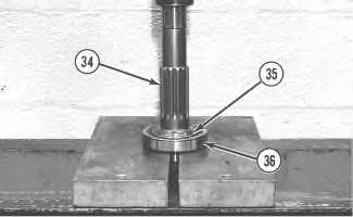
Illustration 16 g00510598
21. Remove inner race (37) from shaft (34) .
Illustration 17 g00510599
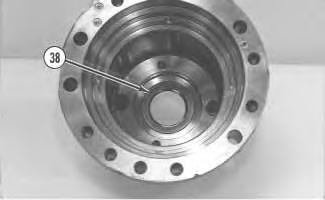
22. Remove lip type seal (38) from the travel motor body.
Illustration 18 g00510605
Illustration 19 g00918957
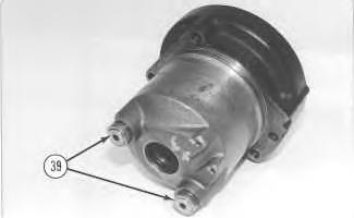
23. Remove two cam plate tension adjusters from the travel motor body. Loosen two nuts (39). Remove two adjusters (40), two springs (43), and two pistons (44) from the travel motor body.
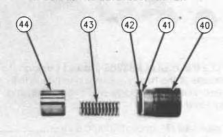
24. Remove O-ring seal (42) and backup ring (41) from each adjuster (40) .
Disassembly Procedure For The Travel Motor On CIPI
Undercarriage Arrangements Which Are Based On 325B Track Type Excavators
Start By:
A. Remove the travel motor. Refer to Disassembly and Assembly, "Travel Motor - Remove" in this manual.
NOTICE
Care must be taken to ensure that fluids are contained during performance of inspection, maintenance, testing, adjusting and repair of the product. Be prepared to collect the fluid with suitable containers before opening any compartment or disassembling any component containing fluids.
Refer to Special Publication, NENG2500, "Caterpillar Tools and Shop Products Guide" for tools and supplies suitable to collect and contain fluids on Caterpillar products.
Dispose of all fluids according to local regulations and mandates.
1. Thoroughly clean the outside of the travel motor prior to disassembly. Fasten the travel motor to a suitable holding fixture in a vertical position. The weight of the travel motor is approximately 50 kg (110 lb).
2. Put an alignment mark across the head and the body of the travel motor for assembly purposes. The head must be reinstalled in the head's original position on the travel motor body.
Illustration 20
3. Remove ten socket head bolts (1) and head (2) from the travel motor body.
Note: During the removal of head (2) from the travel motor body, be careful not to damage the mating surfaces of the components.
Illustration 21
Illustration 22
4. Turn over head (2). Remove O-ring seal (6), shims (5), port plate (4), and bearing (3) from the head. Remove the two check valve assemblies from the head.
Note: There is a retainer that is located under spring (9). This retainer is a press fit in head (2). Do not remove the retainer.
5. Insert a dowel rod with a small diameter into hole "X". Tap the dowel rod with a plastic hammer in order to remove spring (9), poppet (8) and seat (7) from the head.
g00510326
g00510341
g00510349
Illustration 23
g00510351
6. Remove three fittings (10) and plugs (11) from the head. Remove the O-ring seal from each fitting.
Illustration 24
g00510352
7. Remove three O-ring seals (12) and washer set (13) from the travel motor body.
8. Place a shop towel over brake piston (14). Retain brake piston (14) by hand, and apply approximately 525 kPa (75 psi) of shop air pressure to brake release port "Y". Make sure that the shop air pressure is free of water. Brake piston (14) will move up the piston guide, and out of the piston guide. Remove brake piston (14) from the travel motor body.
Illustration 25 g00510353
9. Remove O-ring seals (15) and (17) from the brake piston. Remove backup rings (16) and (18) from the brake piston.
Illustration 26 g00510356
10. Remove piston guide (19), five friction plates (20) and the four steel plates from the travel motor body.
Illustration 27 g00510359
11. Remove O-ring seal (21) and backup ring (22) from the piston guide.
Note: Do not allow the components of barrel assembly (23) to come apart during the removal from the travel motor. All of the components in the barrel assembly must be reinstalled in the component's original location.
12. Use two large screwdrivers and slowly remove barrel assembly (23) from the travel motor body, as shown. Do not allow the components to fall apart.
13. Shoe retainer (24) and piston shoe assemblies (25) are nonserviceable separately. Prior to the removal of the shoe retainer and the piston shoe assemblies from barrel (26), put identification marks on piston shoe assemblies (25) for assembly purposes. Identification marks are used to identify the piston shoe assembly's location in shoe retainer (24) and barrel (26). The piston shoe assemblies must be reinstalled in the piston shoe assembly's original bores in the shoe retainer and the barrel.
14. Remove shoe retainer (24) and piston shoe assemblies (25) from barrel (26). Separate the piston shoe assemblies from the shoe retainer.
Illustration 28 g00510365
Illustration 29 g00510502
15. Remove guide (27), spacer (28) and nine springs (29) from the barrel.
16. Remove cam plate (30) from the body of the travel motor.
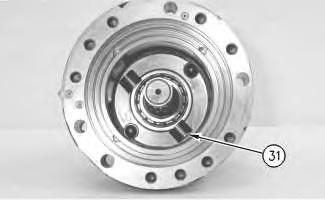 Illustration 30
g00510504
Illustration 31
g00510547
Illustration 30
g00510504
Illustration 31
g00510547
Illustration 32 g00510550
17. Remove two keys (31) and the two locating pins (not shown) from the travel motor body.
Illustration 33
18. Remove O-ring seal (33) from the travel motor body.
19. Use a soft faced hammer to remove shaft assembly (34) from the travel motor body. Remove the shaft assembly in the direction that is indicated by the arrow. Refer to Illustration 33.
Illustration 34
20. Remove retaining rings (35) from each side of bearing (36). Push shaft (34) out of bearing (36) with a press.
g00510551
g00510595
Illustration 35
21. Remove inner race (37) from shaft (34) .
Illustration 36
22. Remove lip type seal (38) from the travel motor body.
Illustration 37
23. Remove two cam plate tension adjusters from the travel motor body. Loosen two nuts (39). Remove two adjusters (40), two springs (43), and two pistons (44) from the travel motor body.
24. Remove O-ring seal (42) and backup ring (41) from each adjuster (40) .
Disassembly Procedure For The Travel Motor On CIPI Undercarriage Arrangements Which Are Based On 325C Track Type Excavators
Start By:
A. Remove the travel motor. Refer to Disassembly and Assembly, "Travel Motor - Remove" in this manual.
NOTICE
Care must be taken to ensure that fluids are contained during performance of inspection, maintenance, testing, adjusting and repair of the product. Be prepared to collect the fluid with suitable containers before opening any compartment or disassembling any component containing fluids.
Refer to Special Publication, NENG2500, "Caterpillar Tools and Shop Products Guide" for tools and supplies suitable to collect and contain fluids on Caterpillar products.
Dispose of all fluids according to local regulations and mandates.
1. Thoroughly clean the outside of the travel motor prior to disassembly.
2. Fasten the travel motor to a suitable holding fixture in a vertical position. The weight of the travel motor is 60 kg (132 lb).
3. Put an alignment mark across the head and the body of the travel motor for assembly purposes. The head must be reinstalled in the head's original position on the body of the travel motor.
Illustration 38 g00510326
Note: During the removal of head (2) from the travel motor, be careful not to damage the mating surfaces of the components.
4. Remove bolts (1) .
5. Remove head (2) from the body of the travel motor.
Illustration 39 g00510341
Illustration 40 g00510349
6. Turn over head (2) .
7. Remove O-ring seal (6), shims (5), port plate (4), and bearing (3) from the head.
8. Remove the check valve assemblies from the head.
Note: There is a retainer under spring (9). This retainer is a press fit in head (2). Do not remove the retainer.
9. Insert a dowel rod with a small diameter into Hole (X). Tap the dowel rod with a plastic hammer in order to remove spring (9), poppet (8), and seat (7) from the head.
Illustration 41
g00510351
10. Remove three fittings (10) and plugs (11) from the head. Remove the O-ring seal from each fitting.
Illustration 42
g00878239
11. Remove O-ring seals (13) and washer set (12) from the body of the travel motor.
12. Place a shop towel over brake piston (14). Retain brake piston (14) by hand, and apply approximately 525 kPa (75 psi) of shop air pressure to brake release Port (Y). Make sure
that the shop air pressure is free of water. Brake piston (14) will move up the piston guide, and out of the piston guide. Remove brake piston (14) from the body of the travel motor.
Illustration 43
g00878248
13. Remove O-ring seal (16) from the brake piston. Remove backup ring (15) from the brake piston.
14. Remove O-ring seal (17) from the brake piston. Remove backup ring (18) from the brake piston.
Illustration 44
g00510356
15. Remove piston guide (19), five friction plates (20) and the four steel plates from the body of the travel motor.

Illustration 45
g00510359
16. Remove O-ring seal (21) from the piston guide. Remove backup ring (22) from the piston guide.
g00510365
Note: Do not allow the components of barrel assembly (23) to come apart during the removal from the travel motor. All of the components in the barrel assembly must be reinstalled in the component's original location.
17. Use two large screwdrivers, as shown. Slowly remove barrel assembly (23) from the body of the travel motor. Do not allow the components to fall apart.
Illustration 47
g00878253
Note: Shoe retainer (24) and piston shoe assemblies (25) are nonserviceable separately. Prior to the removal of the shoe retainer and the piston shoe assemblies from barrel (26), put identification marks on piston shoe assemblies (25) for assembly purposes. Identification marks are used to identify the piston shoe assembly's location in shoe retainer (24) and barrel (26). The piston shoe assemblies must be reinstalled in the piston shoe assembly's original bores in the shoe retainer and the barrel.
18. Remove shoe retainer (24) and piston shoe assemblies (25) from barrel (26). Separate the piston shoe assemblies from the shoe retainer.
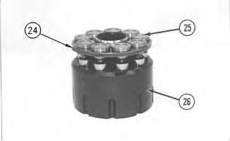
Illustration 48
g00510504
19. Remove guide (27), spacer (28), and springs (29) from the barrel.
Illustration 49
20. Remove cam plate (30) from the body of the travel motor.
Illustration 50 g00510550
21. Remove two keys (31) and the two locating pins (not shown) from the body of the travel motor.
Illustration 51 g00510551
Suggest:
If the above button click is invalid.
Please download this document first, and then click the above link to download the complete manual.
Thank you so much for reading

22. Remove O-ring seal (33) from the body of the travel motor.
23. Use a soft faced hammer to remove shaft assembly (34) from the body of the travel motor. Remove the shaft assembly in the direction that is indicated by the arrow. Refer to
Illustration 51.
24. Remove retaining rings (35) from each side of bearing (36). Push shaft (34) out of bearing (36) with a press.
25. Remove inner race (37) from shaft (34) .
Illustration 52 g00510595
Illustration 53
g00510598