Previous Screen
Product: EXCAVATOR
Model: 322C EXCAVATOR HEK
Configuration: 322C L Hydraulic Excavator HEK00001-UP (MACHINE) POWERED BY 3126B Engine
Disassembly and Assembly
3126B Engines for Caterpillar Built Machines
Unit Injector Hydraulic Pump - Install
SMCS - 1714-012
Installation Procedure Table 1
Required Tools
NOTICE
Keep all parts clean from contaminants.
Contaminants may cause rapid wear and shortened component life.
Shutdown SIS
g00727636
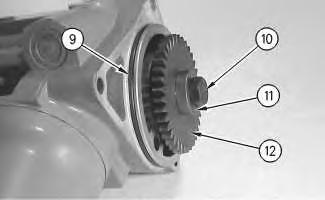
1. Position drive gear (12) on the unit injector hydraulic pump. Install washer (11) and bolt (10) on the unit injector hydraulic pump. Tighten bolt (10) to a torque of 110 ± 14 N·m (81 ± 10 lb ft).
2. Lubricate O-ring seal (9) with clean engine oil. Install the O-ring seal on the unit injector hydraulic pump.
g00727632
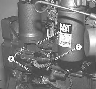
3. Position unit injector hydraulic pump (6) on the timing gear housing. Install three bolts (8) and tighten three bolts (8) to a torque of 28 ± 7 N·m (20 ± 5 lb ft).
4. Install cable strap (7).
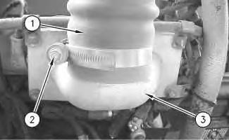
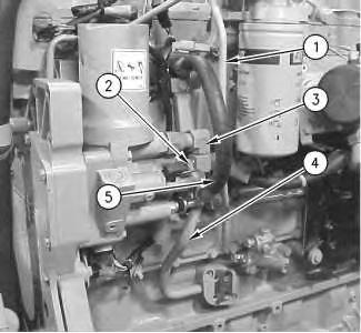
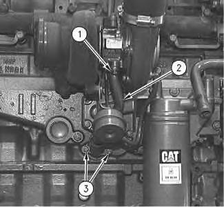
Illustration 1 Illustration 25. Install return line assembly (4) on the engine block and on fitting (3).
6. Reconnect harness assembly (2).
7. Use Tooling (A) to install line assembly (1).
NOTICE
If the hose is not correctly connected the hose will come loose when the engine is started and the engine oil will come out of the hose. Engine damage can result.
NOTICE
Leakage of the high pressure engine oil lines can result in failure of the engine fuel system.
8. Install hose assembly (5) and lock the hose assembly in position. Apply pressure in order to snap the hose assembly into the quick coupling for each of the ends.
Note: Be sure to check the connection by pulling back on the hose.
Copyright 1993 - 2019 Caterpillar Inc. All Rights Reserved. Private Network For SIS Licensees.
Previous Screen
Product: EXCAVATOR
Model: 322C EXCAVATOR HEK
Configuration: 322C L Hydraulic Excavator HEK00001-UP (MACHINE) POWERED BY 3126B Engine
Disassembly and Assembly
3126B Engines for Caterpillar Built Machines
Turbocharger - Remove
SMCS - 1052-011
Removal Procedure
NOTICE
Keep all parts clean from contaminants.
Contaminants may cause rapid wear and shortened component life.
Shutdown
NOTICE
Care must be taken to ensure that fluids are contained during performance of inspection, maintenance, testing, adjusting, and repair of the product. Be prepared to collect the fluid with suitable containers before opening any compartment or disassembling any component containing fluids.
Refer to Special Publication, NENG2500, "Dealer Service Tool Catalog" for tools and supplies suitable to collect and contain fluids on Cat products.
Dispose of all fluids according to local regulations and mandates.
Illustration 1 g00617515
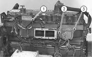
1. Remove bolts (1) and the gasket. Remove bolts (3) and tube assembly (2) from the turbocharger.
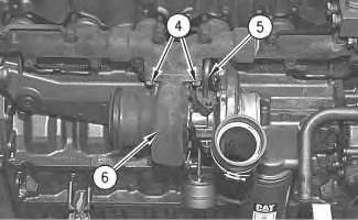
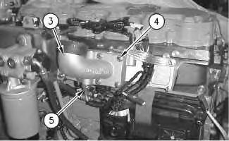
Illustration 2
g00617565
2. Remove the bolts and the gasket in order to disconnect oil supply tube assembly (5) from the turbocharger.
3. Remove nuts (4), turbocharger (6), and the gasket from the exhaust manifold.
Copyright 1993 - 2019 Caterpillar Inc. All Rights Reserved. Private Network For SIS Licensees.
Mon
Previous Screen
Product: EXCAVATOR
Model: 322C EXCAVATOR HEK
Configuration: 322C L Hydraulic Excavator HEK00001-UP (MACHINE) POWERED BY 3126B Engine
Disassembly and Assembly
3126B Engines for Caterpillar Built Machines
Turbocharger - Disassemble
SMCS - 1052-015
Disassembly Procedure
NOTICE
Keep all parts clean from contaminants.
Contaminants may cause rapid wear and shortened component life.
NOTICE
Care must be taken to ensure that fluids are contained during performance of inspection, maintenance, testing, adjusting, and repair of the product. Be prepared to collect the fluid with suitable containers before opening any compartment or disassembling any component containing fluids.
Refer to Special Publication, NENG2500, "Dealer Service Tool Catalog" for tools and supplies suitable to collect and contain fluids on Cat products.
Dispose of all fluids according to local regulations and mandates.
Illustration 1
g01025751
1. Place alignment marks on the two housings and the cartridge assembly for the correct alignment during assembly.
2. Disconnect hose (4) from compressor housing (3).
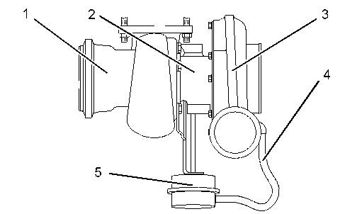
3. Remove waste gate (5) from turbine housing (1).
4. Remove turbine housing (1).
5. Remove compressor housing (3) from cartridge assembly (2).
Previous Screen
Product: EXCAVATOR
Model: 322C EXCAVATOR HEK
Configuration: 322C L Hydraulic Excavator HEK00001-UP (MACHINE) POWERED BY 3126B Engine
Disassembly and Assembly
3126B Engines for Caterpillar Built Machines
Turbocharger - Assemble
SMCS - 1052-016
Assembly Procedure
NOTICE
Keep all parts clean from contaminants.
Contaminants may cause rapid wear and shortened component life.
Shutdown SIS
1. Position compressor housing (3) on cartridge assembly (2) and align the marks on the components.
2. Position turbine housing (1) on cartridge assembly (2) and align the marks on the components.
3. Install waste gate (5).
4. Connect hose (4) to compressor housing (3).
Copyright 1993 - 2019 Caterpillar Inc. All Rights Reserved. Private Network For SIS Licensees.
Previous Screen
Product: EXCAVATOR
Model: 322C EXCAVATOR HEK
Configuration: 322C L Hydraulic Excavator HEK00001-UP (MACHINE) POWERED BY 3126B Engine
Disassembly and Assembly
3126B Engines for Caterpillar Built Machines
Turbocharger - Install
SMCS - 1052-012
Installation Procedure
NOTICE
Keep all parts clean from contaminants.
Contaminants may cause rapid wear and shortened component life.
Shutdown SIS
1. Inspect the turbocharger gasket for wear or damage. If the turbocharger gasket is worn or damaged, use a new part for replacement.
2. Apply 5P-3931 Anti-Seize Compound on the threads of the mounting studs for the turbocharger.
3. Position the turbocharger gasket and turbocharger (6) on the exhaust manifold. Install nuts (4) that fasten turbocharger (6) to the exhaust manifold.
4. Tighten the locknuts that fasten the turbocharger to the exhaust manifold.
Tighten the 3E-8017 Locknut with the Spiralock thread to the following torque: ... 54 ± 5 N·m (40 ± 4 lb ft)
Tighten the standard 9X-6620 Locknut to the following torque: ... 70 ± 5 N·m (50 ± 4 lb ft)
5. Inspect the gaskets for oil supply tube assembly (5) and tube assembly (2). If the gaskets are worn or damaged, use a new part for replacement.
6. Position tube assembly (2) and the gasket on turbocharger (6). Install bolts (1) on the turbocharger and install bolts (3) on the cylinder block.
7. Install the gasket for oil supply tube assembly (5) and connect oil supply tube assembly (5) to turbocharger (6).
Copyright 1993 - 2019 Caterpillar Inc. All Rights Reserved. Private Network For SIS Licensees.
Mon Sep 16 21:54:37 UTC+0800 2019
Illustration 2 g00617515Shutdown SIS
Previous Screen
Product: EXCAVATOR
Model: 322C EXCAVATOR HEK
Configuration: 322C L Hydraulic Excavator HEK00001-UP (MACHINE) POWERED BY 3126B Engine
Disassembly and Assembly
3126B Engines for Caterpillar Built Machines
Exhaust Manifold - Remove and Install
SMCS - 1059-010
Removal Procedure
Start By:
a. Remove the turbocharger. Refer to Disassembly and Assembly, "Turbocharger - Remove".
Installation Procedure
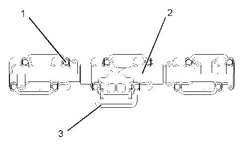
Table 1
Required Tools
A 2P-2333 High Temperature Sealer 1
B 5P-3931 Anti-Seize Compound 1
NOTICE
Excessive use of sealant can cause damage to components.
To avoid component damage use only the amount of sealant necessary for the application.
Illustration 2
g01025883
Note: Apply Tooling (A) to the outside diameter of the male ends of exhaust manifold (2) if exhaust manifold (2) is disassembled. Assemble exhaust manifold (2) and remove the excess sealer from the joints.
1. Apply Tooling (B) to the threads of bolts (1). Position the gaskets and exhaust manifold (2) on the cylinder head assembly. Install locks (3) and bolts (1).
Illustration 3 g00617739
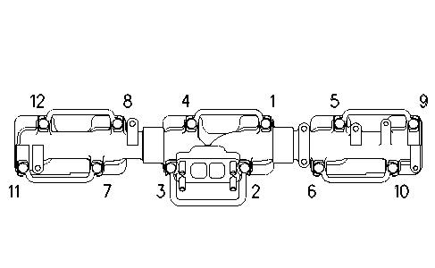
2. Tighten bolt (1) through bolt (12) in a numerical sequence. Tighten bolts to 4 ± 1 N·m (35 ± 9 lb in).
3. Tighten bolt (1) through bolt (12) in a numerical sequence 45 ± 5 N·m (33 ± 4 lb ft).
Note: Prior to starting or running the engine, allow the sealant in the exhaust manifold joints to air dry for 24 hours.
End By:
a. Install the turbocharger. Refer to Disassembly and Assembly, "Turbocharger - Install". Copyright 1993 - 2019
Previous Screen
Product: EXCAVATOR
Model: 322C EXCAVATOR HEK
Configuration: 322C L Hydraulic Excavator HEK00001-UP (MACHINE) POWERED BY 3126B Engine
Disassembly and Assembly
3126B Engines for Caterpillar Built Machines
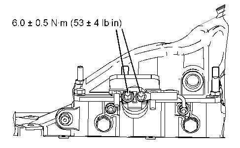
Air Inlet Heater Solenoid - Remove and Install
SMCS - 1090-010-OD
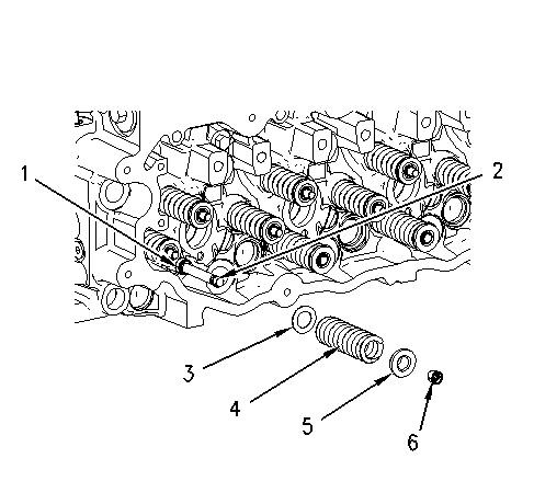
Illustration 1 g01025992
Copyright 1993 - 2019 Caterpillar Inc.
All Rights Reserved.
Private Network For SIS Licensees.
Shutdown SIS
Shutdown SIS
Previous Screen
Product: EXCAVATOR
Model: 322C EXCAVATOR HEK
Configuration: 322C L Hydraulic Excavator HEK00001-UP (MACHINE) POWERED BY 3126B Engine
Disassembly and Assembly
3126B Engines for Caterpillar Built Machines
Air Inlet Cover - Remove and Install
SMCS - 1087-010-CH
Removal Procedure
Start By:
a. Remove the air inlet heater. Refer to Disassembly and Assembly, "Air Inlet HeaterRemove and Install".
b. Remove the fuel filter base. Refer to Disassembly and Assembly, "Fuel Filter BaseRemove and Install".
Illustration 1
g00618364
1. Disconnect harness assembly (2) for the boost sensor.
2. Remove the bolts and mounting bracket (1) for the fuel filter base.
3. Remove the bolts and air inlet cover (3).