Shutdown SIS
Previous Screen
Product: EXCAVATOR
Model: 322C EXCAVATOR MAR
Configuration: 322C L, 322C LN Hydraulic Excavators MAR00001-UP (MACHINE) POWERED BY 3126 Engine
Disassembly and Assembly
322C Excavator Machine Systems
Bucket Linkage - Remove
SMCS - 6513-011
Removal Procedure
Note: Refer to Specifications in order to identify the bucket families.
Illustration 1
g00697085
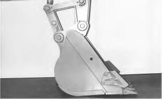
1. Start the engine. Park the machine on a hard, level surface. Position the stick and the bucket, as shown. Shut off the engine.
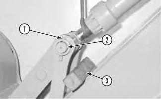
g00622353
2. Remove nuts (2) and retaining bolt (3) from bucket pin (1).
Note: Machines that do not have bolt (3) have a pin and retaining rings. Remove the retaining rings and the pin from machines that do not have bolt (3).
g00625142
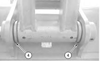
3. Slide O-ring seals (4) off the pin joints between the bucket and the power link and onto the flanges of the bucket, as shown.
When the pin assembly is removed, the linkage assembly may swing out of the bucket. To prevent possible personal injury, do not stand in front of the linkage assembly when the pin assembly is being removed.
4. Drive bucket pin (1) out of the bucket.
5. Remove O-ring seals (4) from the flanges on the bucket. Refer to illustration 2.
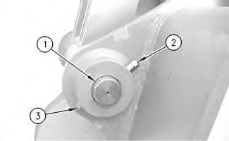 Illustration 2
Illustration 3
Illustration 2
Illustration 3
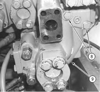
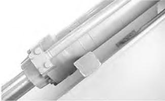
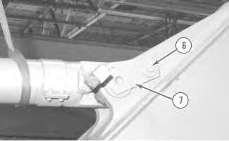
6. Extend the bucket cylinder until idler link (7) is resting on the bucket. Shut off the engine.
7. Fasten a suitable lifting device to power link (5), as shown. Raise the power link until the power link is in a horizontal position, as shown.
8. Remove nuts (8) and retaining bolt (9) from pin (6).
Note: Machines that do not have bolt (9) have a pin and retaining rings. Remove the retaining rings and the pin from machines that do not have bolt (9).
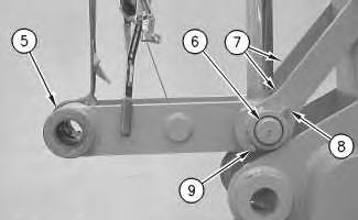
9. Use a hammer and a punch in order to remove pin (6) from idler links (7), power link (5), and the rod end of the bucket cylinder.
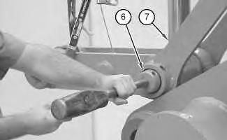
Note: Machines are equipped with shims between the power link and the idler links.
10. Remove power link (5). The weight of the power links will vary from approximately 60 kg (132 lb) to approximately 130 kg (287 lb).
11. Remove the shims on the outside of power link (5).
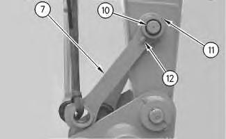
Illustration 4 g00687519 Illustration 5 g01012145g00888143
12. Fasten a suitable lifting device to left hand idler link (7), as shown.
13. Remove two nuts (12) and retaining bolt (11) from pin (10).
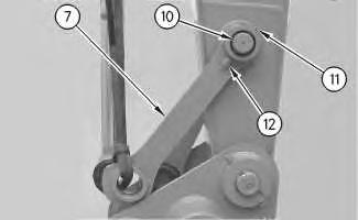
14. Use a hammer and a punch to drive pin (10) into the stick. Drive the pin until the idler link is free.
15. Remove the idler link from the left side.
16. Refasten the hoist to the right hand idler link.
17. Remove pin (10) and the right hand idler link.
18. The weight of pin (10) and the idler link on the right side will vary from 30 kg (66 lb) to 45 kg (100 lb).
Shutdown SIS
Previous Screen Product: EXCAVATOR Model: 322C EXCAVATOR MAR
322C
Bucket Linkage Bearings and Seals - Remove
SMCS - 6513-011-BD; 6513-011-SA
Removal Procedure Table 1
Required Tools
(230 Volt) is available.
Start By:
a. Remove the bucket control linkage. Refer to Disassembly and Assembly, "Bucket LinkageRemove".
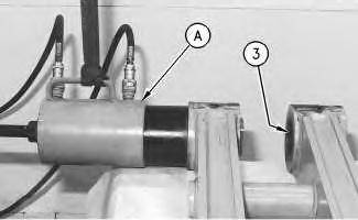
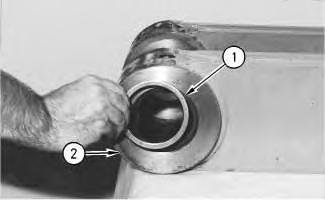
Illustration 2 g00698294
2. Attach an suitable lifting device to Tooling (A), as shown.
3. Use Tooling (A) to remove sleeve bearing (3) from the open end of the power link.
4. Use Tooling (A) to remove the sleeve bearing from the opposite side of the power link.
5. Remove the sleeve bearings from the closed end of the power link by using a chisel or by cutting.
6. Remove lip seals (4) from the bore for the idler link in the stick.
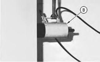
Illustration 4 g00698417
7. Attach an suitable lifting device to Tooling (B), as shown.
8. Use Tooling (B) to remove the sleeve bearing from the stick.
9. Use Tooling (B) to remove the sleeve bearing from the opposite side of the stick.
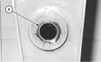
Illustration 3 g00698407Shutdown SIS
Previous Screen
Product: EXCAVATOR
Model: 322C EXCAVATOR MAR
Configuration: 322C L, 322C LN Hydraulic Excavators MAR00001-UP (MACHINE) POWERED BY 3126 Engine
Disassembly and Assembly
322C Excavator Machine Systems Media
Bucket Linkage Bearings and Seals - Install
SMCS - 6513-012-BD; 6513-012-SA
Installation Procedure Table 1
Required Tools
Tool Part Number Part Description
A 1P-0510 Driver Gp 1
B 5P-0960 Molybdenum Grease -
Note: Refer to Specifications in order to identify the bucket families.
1. Make sure that the bores in the power link and the bore in the stick are thoroughly clean and free of dirt and debris prior to the installation of the sleeve bearings.
Note: Make sure that the bearings are installed in the bore so that the identification numbers of the bearings are facing outward.
Illustration 1 g00698602
2. Lower the temperature of sleeve bearings (5) that will be installed in the closed end of power link (2) to −40 °C (−40 °F).
3. Use Tooling (A) to install sleeve bearings (5) in the closed end of power link (2). Install the sleeve bearings until Dimension (X) is achieved.
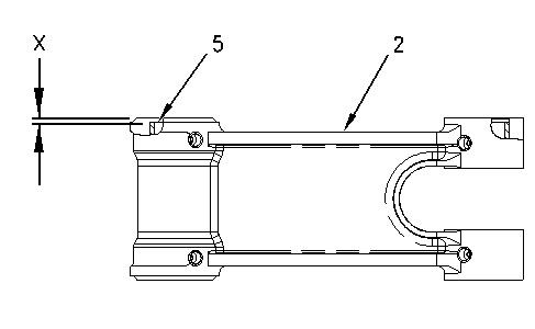
4. Use the following table to determine the correct Dimension (X).
Table 2
Table for Dimension (X)
Illustration 2
g00698673
5. Lower the temperature of sleeve bearings (3) that will be installed in the open end of power link (2) to −40 °C (−40 °F).
6. Use Tooling (A) to install two sleeve bearings (3) in the open end of power link (2). Install the sleeve bearings until dimension (Y) is achieved.
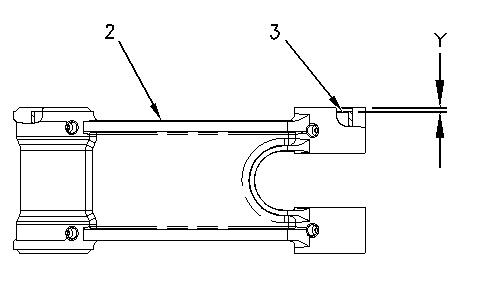
7. Use the following table to determine the correct Dimension (Y).
Table 3
Table for Dimension (Y)
Bucket Family Dimension (Y)
B-Family 7.2 ± 0.8 mm (0.28 ± 0.03 inch)
C-Family 6.10 ± 0.30 mm (0.240 ± 0.012 inch)
Illustration 3
g00698265
8. Use Tooling (A) to install lip seals (1) in power link (2). Install the lip seals with the sealing lip toward the outside of the bore. Install the lip seals below the outside surface of the power link.
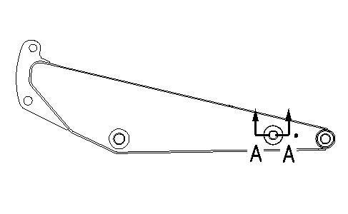
Illustration 4 g00698695
Illustration 5 g00698698
View A-A
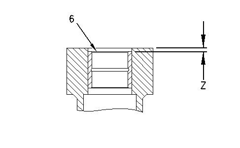
9. Lower the temperature of two sleeve bearings (6) that will be installed in the stick to −40 °C (−40 °F).
10. Use Tooling (A) to install sleeve bearings (6) in the stick. Install the sleeve bearings until Dimension (Z) is achieved. Dimension (Z) must be 7.5 ± 0.8 mm (0.30 ± 0.03 inch).
11. Install lip seals (4) in the stick. Install the lip seals with the sealing lip toward the outside of the bore. Install the lip seals below the outside surface of the stick.
12. Apply a thin coat of Tooling (B) to all sleeve bearings.
13. Apply a thin coat of Tooling (B) to the sealing lip of all lip seals.
End By:
a. Install the bucket control linkage. Refer to Disassembly and Assembly, "Bucket LinkageInstall".
Copyright 1993 - 2019 Caterpillar Inc. All Rights Reserved. Private Network For SIS Licensees.
Shutdown SIS
Previous Screen
Product: EXCAVATOR
Model: 322C EXCAVATOR MAR
Configuration: 322C L, 322C LN Hydraulic Excavators MAR00001-UP (MACHINE) POWERED BY 3126 Engine
Disassembly and Assembly
322C Excavator Machine Systems
Bucket Linkage - Install
SMCS - 6513-012
Installation Procedure Table 1 Required Tools
Tool Part Number Part Description Qty
A 5P-0960 Molybdenum Grease
Note: Make sure that the pin bore in the stick, the bores in the bucket, and the bores in the link assembly are thoroughly clean and free of dirt and debris prior to the installation of the bucket control linkage.
1. Apply Tooling (A) on the sleeve bearings and on the lip type seals in the stick and in the bores of the bucket control linkage. Apply Tooling (A) in the bores in the bucket.
Illustration 1 g00888160
2. Apply Tooling (A) to pin (10).
3. Fasten an suitable lifting device to the right hand idler link. Place the right hand idler link in position on the stick. Install pin (10) in the right hand idler link and the stick. The weight of pin (10) and the right hand idler link will vary from approximately 30 kg (66 lb) to approximately 45 kg (100 lb).
4. Install left hand idler link (7).
5. Install bolt (11) in the left hand idler link and in pin (10), as shown.
6. Install nuts (12).
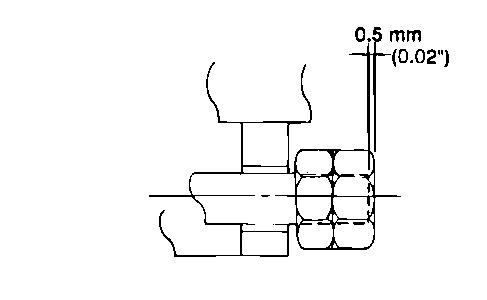
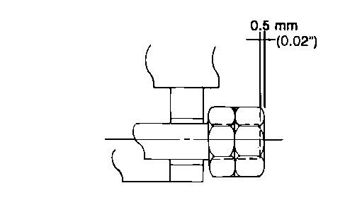
7. Tighten nuts (12), as shown. Tighten the outside nut until the nut is 0.5 mm (0.02 inch) beyond the end of the retaining bolt. Tighten the inside nut against the outside nut to a torque of 240 ± 40 N·m (177 ± 30 lb ft).
Note: Make sure that the grease fitting on the rod end of the bucket cylinder is facing away from the stick.
Note: Make sure that the grease fittings on the power link are facing away from the bucket.
Illustration 2 g00356648Illustration 3
g00687519
8. Fasten a suitable lifting device to power link (5), as shown. The weight of the power link will vary from 60 kg (132 lb) to 130 kg (287 lb). Position the power link so that pin (6) can be installed into the idler links, the power link, and the rod end of the bucket cylinder.
9. Install a shim between each idler link and the power link. Apply Tooling (A) to pin (6). Install pin (6).
10. Install bolt (9) in the left hand idler link and in pin (6), as shown.
Note: Machines that do not have bolt (9) have a pin and retaining rings. Install the pin and the retaining rings in machines that do not have bolt (9).
11. Install two nuts (8).
Illustration 4
g00356648
12. Tighten nuts (8), as shown. Tighten the outside nut until the nut is 0.5 mm (0.02 inch) beyond the end of the retaining bolt. Tighten the inside nut against the outside nut to a torque of 460 ± 60 N·m (340 ± 44 lb ft).
Illustration 5
Typical example
g00622404
13. Remove the wood block from the bucket cylinder.
Illustration 6
g00625142
14. Position new O-ring seals (4) on the bucket, as shown.
15. Retract the bucket cylinder until the bore in the power link aligns with the bores in the bucket.
Illustration 7
g00622353
16. Apply Tooling (A) to pin (1). Install pin (1) in the bucket and the power link.
17. Install bolt (3), as shown.
Note: Machines that do not have bolt (3) have a pin and retaining rings. Install the pin and the retaining rings in machines that do not have bolt (3).
18. Install nuts (2).
Illustration 8
g00356648
19. Tighten nuts (2), as shown. Tighten the outside nut until the nut is 0.5 mm (0.02 inch) beyond the end of the retaining bolt. Tighten the inside nut against the outside nut to a torque of 240 ± 40 N·m (177 ± 30 lb ft).
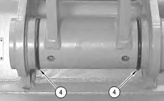
Illustration 9
g00698046
20. Position O-ring seals (4) over the joint between the bucket and the power link, as shown.
21. Lubricate the pins.
Reference: Refer to Operation and Maintenance Manual, "Boom, Stick and Bucket Linkage - Lubricate" for the correct lubrication procedure.
Copyright 1993 - 2019 Caterpillar Inc.
All Rights Reserved.
Private Network For SIS Licensees.
Fri Sep 13 23:22:08 UTC+0800 2019
Previous Screen
Product: EXCAVATOR
Model: 322C EXCAVATOR MAR
Configuration: 322C L, 322C LN Hydraulic Excavators MAR00001-UP (MACHINE) POWERED BY 3126 Engine
Disassembly and Assembly
322C Excavator Machine Systems
Bucket Cylinder - Remove and Install
SMCS - 5457-010
Removal Procedure
Cylinders equipped with lock valves can remain pressurized for very long periods of time, even with the hoses removed.
Failure to relieve pressure before removing a lock valve or disassembling a cylinder can result in personal injury or death.
Ensure all pressure is relieved before removing a lock valve or disassembling a cylinder.
Note: Cleanliness is an important factor. Before the disassembly procedure, the exterior of the component should be thoroughly cleaned. This will help to prevent dirt from entering the internal mechanism.
NOTICE
Care must be taken to ensure that fluids are contained during performance of inspection, maintenance, testing, adjusting and repair of the product. Be prepared to collect the fluid with suitable containers before opening any compartment or disassembling any component containing fluids.
Refer to Special Publication, NENG2500, "Caterpillar Dealer Service Tool Catalog" for tools and supplies suitable to collect and contain fluids on Caterpillar products.
Dispose of all fluids according to local regulations and mandates.
At operating temperature, the hydraulic oil is hot and under pressure. Hot oils can cause burns.
To prevent possible personal injury, release the pressure in the work tool hydraulic circuit (boom, stick, bucket, and swing), travel circuits, and the hydraulic oil tank at the filler cap before any hydraulic lines or components are disconnected or removed.
Remove the filler cap only when the engine is stopped and the filler cap is cool enough to touch.
Note: Put identification marks on all lines, on all hoses, on all wires, and on all tubes for installation purposes. Plug all lines, hoses, and tubes. This helps to prevent fluid loss and this helps to keep contaminants from entering the system.
1. Release the hydraulic system pressure. Refer to Disassembly and Assembly, "System PressureRelease".
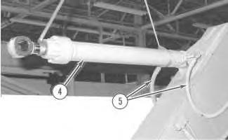
Illustration 1
g00555749
2. Fasten a suitable lifting device to the rod end of the bucket cylinder, as shown. Put suitable blocking (3) under the link assemblies as a support.
3. Remove the nuts and retaining bolt (1) . Remove pin (2) .
4. Note the location and the quantity of the shims between the power link and the idler link. Remove the shims.
Illustration
5. Raise bucket cylinder (4) until bucket cylinder (4) is level. Fasten a suitable lifting device to the head end of bucket cylinder (4) , as shown. Disconnect hose assemblies (5) .
Illustration
6. Remove retaining bolt (6) , pin assembly (7) , and the spacer. Remove the bucket cylinder. The weight of the bucket cylinder is approximately 150 kg (330 lb).
7. Note the location and the quantity of shims on both sides of the bucket cylinder at the stick pin. Remove the shims.
Disassembly and Assembly Information
Cylinders equipped with lock valves can remain pressurized for very long periods of time, even with the hoses removed.
Failure to relieve pressure before removing a lock valve or disassembling a cylinder can result in personal injury or death.
Ensure all pressure is relieved before removing a lock valve or disassembling a cylinder.
Note: Apply a light film of hydraulic oil to all components before assembly.
1. Apply Tooling (B) to seal (1) prior to assembly.
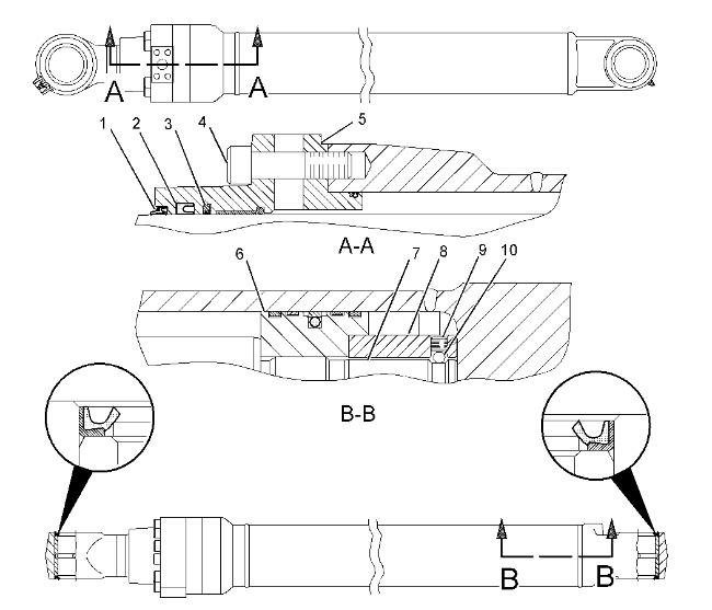
2. Apply clean hydraulic oil on the lip of seal (1) , seal (2) , and seal (3) .
3. Apply Tooling (C) to the threads of head (5) .
4. Lubricate the threads of rod assembly (7) with Tooling (C) .
5. Tighten locknut (8) to a torque of 7600 ± 380 N·m (5605 ± 280 lb ft).
6. Install ball (10) and setscrew (9) in locknut (8) . Tighten setscrew (9) to a torque of 57 ± 10 N·m (42 ± 7 lb ft).
7. Lubricate the outside of piston (6) with Tooling (C) .
8. Tighten bolts (4) to a torque of 267 ± 40 N·m (197 ± 30 lb ft).
Installation Procedure
Table 2
Required Tools
Tool Part Number Part Description Qty
D 5P-0960 Grease Cartridge 1
Note: Cleanliness is an important factor. Before assembly, all parts should be thoroughly cleaned in cleaning fluid. Allow the parts to air dry. Wiping cloths or rags should not be used to dry parts. Lint may be deposited on the parts which may cause later trouble. Inspect all parts. If any parts are worn or damaged, use new parts for replacement.
Illustration 5
g00477379
1. Fasten a suitable lifting device to bucket cylinder (4) . The weight of bucket cylinder (4) is approximately 150 kg (330 lb). Place bucket cylinder (4) in position in the stick. Lower the head end of bucket cylinder (4) into the brackets on top of the stick. Make sure that the pin bores in the stick are in alignment with the pin bores in the bucket cylinder. Make sure that the grease fittings in the head end and in the rod end of bucket cylinder (4) are facing away from the stick.
2. Install the shims on both sides of the bucket cylinder at the bore for pin assembly (7) .
3. Install pin assembly (7) .
4. Install retaining bolt (6) . Tighten retaining bolt (6) to a torque of 460 ± 60 N·m (340 ± 44 lb ft)
Illustration 6 g00477372
5. Install O-ring seals in the ends of hose assemblies (5) . Connect hose assemblies (5) to bucket cylinder (4) .
Illustration 7 g00555749
6. Lower the bucket cylinder between the link assemblies. Install the shims on both sides of the power link between the power link and the idler links.
7. Apply a thin coat of Tooling (D) on pin (2) . Make sure that the bore in the bucket cylinder rod is in alignment with the bores in the link assemblies. Install pin (2) . Install retaining bolt (1) and the two nuts.
8. Tighten the nuts on retaining bolt (1) . Tighten the outside nut until the nut is 0.5 mm (0.02 inch) beyond the end of the retaining bolt, as shown. Tighten the inside nut against the outside nut to a torque of 460 ± 60 N·m (340 ± 44 lb ft).
9. Fill the hydraulic oil tank with oil to the correct level. Refer to Operation and Maintenance Manual, "Refill Capacities".
10. Start the engine, and run the engine at a low idle speed. Raise the bucket from the ground. Extend and retract the bucket cylinder approximately ten times in order to remove the air from the hydraulic system.
11. Recheck the oil level in the hydraulic oil tank. If necessary, refill the hydraulic oil tank to the correct level.
Illustration 8 g00478086Shutdown SIS
Previous Screen
Product: EXCAVATOR
Model: 322C EXCAVATOR MAR
Configuration: 322C L, 322C LN Hydraulic Excavators MAR00001-UP (MACHINE) POWERED BY 3126 Engine
Disassembly and Assembly
322C Excavator Machine Systems Media
Drift Reduction Valve (Stick) - Remove
SMCS - 5143-011-JJ
Removal Procedure Table 1
Required Tools
Tool Part Number Part Description Qty
A FT-2674 Vacuum Cap 1
Start By:
a. Release the hydraulic system pressure. Refer to Disassembly and Assembly, "Hydraulic System Pressure - Release" .
NOTICE
Keep all parts clean from contaminants.
Contamination of the hydraulic system with foreign material will reduce the service life of the hydraulic system components.
To prevent contaminants from entering the hydraulic system, always plug or cap the lines, fittings, or hoses as they are disconnected. Cover any disassembled components and clean them properly before assembly.
Clean the hydraulic system properly after any major component exchange or especially after a component failure, to remove any contamination.
Care must be taken to ensure that fluids are contained during performance of inspection, maintenance, testing, adjusting, and repair of the product. Be prepared to collect the fluid with suitable containers before opening any compartment or disassembling any component containing fluids.
Refer to Special Publication, NENG2500, "Dealer Service Tool Catalog" for tools and supplies suitable to collect and contain fluids on Cat® products.
Dispose of all fluids according to local regulations and mandates.
Note: A hydraulic oil sample should be obtained before any maintenance is performed in order to establish the system contaminant level. Refer to Fluid Analysis Laboratory Guide, SEBF3116, "Obtaining an Oil Sample for S·O·S Analysis". Refer to Operation and Maintenance Manual, "Sampling Interval and Location of Sampling Valve" for the correct location.
g00690963
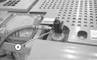
1. Remove the cap from the hydraulic tank. Attach Tooling (A) to the hydraulic tank.
Note: Hook up the air to Tooling (A) in order to create a vacuum in the hydraulic system. This will minimize the leakage from the hose assemblies.
2. Remove bolts (1) and the washers in order to remove cover (2).
3. Remove socket head bolts (3) and the split flanges in order to disconnect hose assembly (4) from the stick drift reduction valve.
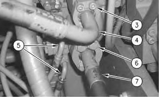
4. Remove bolts (6), the washers, and the split flanges in order to disconnect hose assembly (7) from the stick drift reduction valve.
5. Disconnect hose assemblies (5).
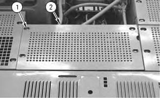 Illustration 2
g00694424
Illustration 3
g00706043
Illustration 2
g00694424
Illustration 3
g00706043
Suggest:
If the above button click is invalid.
Please download this document first, and then click the above link to download the complete manual.
Thank you so much for reading

Illustration 4 g00706051
6. Remove bolts (8).
7. Remove stick drift reduction valve (9).
Copyright 1993 - 2019 Caterpillar Inc. All Rights Reserved. Private Network For SIS Licensees.
Fri Sep 13 23:24:00