
Previous Screen
Product: EXCAVATOR
Model: 322C EXCAVATOR DAA
Configuration: 322C & 322C L Excavators DAA00001-UP (MACHINE) POWERED BY 3126 Engine
Disassembly and Assembly
322C Excavator Machine Systems
Pilot Valve (Joystick) - Disassemble
SMCS - 5059-015
Disassembly Procedure
Start By:
a. Remove the pilot valve. Refer to Disassembly and Assembly, "Pilot Valve (Joystick)Remove".
Note: Cleanliness is an important factor. Before the disassembly procedure, the exterior of the component should be thoroughly cleaned. This will prevent dirt from entering the internal mechanism.
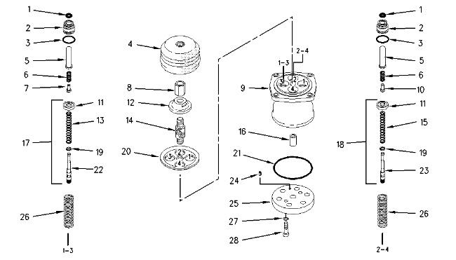
Spool assembly (17) is installed in port (1) and port (3) in the pilot valve.
Spool assembly (18) is installed in port (2) and port (4) in the pilot valve.
Spring seat (7) is installed in port (1) and port (3) in the pilot valve.
Spring seat (10) is installed in port (2) and port (4) in the pilot valve.
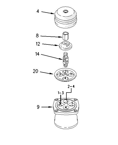
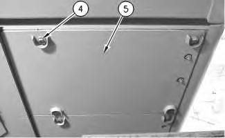
Illustration 1 g00741704 Illustration 2 g00914163 1. Remove rubber boot (4) from the pilot valve.Personal injury can result from being struck by parts propelled by a released spring force.
Make sure to wear all necessary protective equipment.
Follow the recommended procedure and use all recommended tooling to release the spring force.
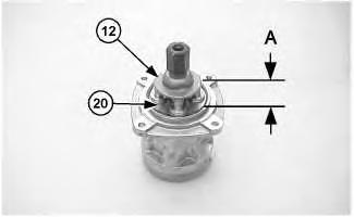
2. Measure Distance (A) from the top of plate (12) to the top of plate (20). Record Dimension (a) for assembly purposes.
3. Tighten nut (8) against plate (12). Remove plate (12), nut (8), and U-joint (14).
Note: If U-joint (14) or plate (12) is not being replaced, do not remove plate (12) from U-joint (14).
4. Remove nut (8) from U-joint (14).
5. Remove plate (12) from U-joint (14).
6. Remove plate (20) from the pilot valve.
Note: The spring seat and the spring may fall out of the rod while you remove the plug.
Note: Mark the seat and the spring for assembly purposes. Spring seat (7) is installed in port (1) and port (3) in the pilot valve. Spring seat (10) is installed in port (2) and port (4) in the pilot valve.
7. Remove plug (2) from the pilot valve.
8. Remove spring seat (7) or (10) and spring (6) from rod (5).
9. Remove rod (5) from plug (2).
10. Remove O-ring seal (3) from plug (2).
11. Remove seal (1) from plug (2).
Note: Spool assembly (17) is installed in Port (1) and Port (3) in the pilot valve. Spool assembly (18) is installed in Port (2) and Port (4) in the pilot valve.
Illustration 4 g0091417912. Remove the spool assembly from the pilot valve.
13. Use the following procedure to disassemble the spool assembly.
Note: Spool (22) is assembled in Port (1) and Port (3) in the pilot valve. Spool (23) is assembled in Port (2) and Port (4) in the pilot valve.
a. Apply pressure to seat (11) by hand. Put the end of the spool in the slotted opening of seat (11). Remove seat (11).
Note: Spring (13) is installed on spool (22). Spring (15) is installed on spool (23).
b. Remove spring (13) or spring (15) from the spool.
c. Remove washer (19) from the spool.
14. Remove spring (26) from the pilot valve.
15. Repeat Steps 7 through 14 in order to remove the other three spool assemblies.
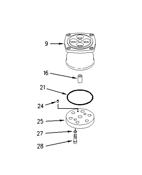
16. Remove bolts (28) and washers (27).
17. Remove plate (25) from the pilot valve.
18. Remove spring pin (24) from plate (25).
19. Remove O-ring seal (21) from valve body (9).
20. Remove bushing (16) from valve body (9). Copyright 1993 - 2019 Caterpillar Inc. All
Previous Screen
Product: EXCAVATOR
Model: 322C EXCAVATOR DAA
Configuration: 322C & 322C L Excavators DAA00001-UP (MACHINE) POWERED BY 3126 Engine
Disassembly and Assembly
322C Excavator Machine Systems Media
Pilot Valve (Joystick) - Assemble
SMCS - 5059-016
Assembly Procedure
Table 1
Required Tools
Tool Part Number Part Description
A 1U-6396 O-Ring Assembly Compound 1
B 9S-3263 Thread Lock Compound 1
Note: Cleanliness is an important factor. Before assembly, all parts should be thoroughly cleaned in cleaning fluid. Allow the parts to air dry. Wiping cloths or rags should not be used to dry parts. Lint may be deposited on the parts which may cause later trouble. Inspect all parts. If any parts are worn or damaged, use new parts for replacement. All disassembly and all assembly procedures must be performed on a clean work surface and in a clean hydraulic area. Keep cleaned parts covered and protected at all times.
Note: O-rings, gaskets, and seals should always be replaced. A used O-ring seal may not have the same sealing properties as a new O-ring seal. Use Tooling (A) during the assembly procedure.
g00741704
1. Install bushing (16) in valve body (9).
2. Install new O-ring seal (21) on valve body (9).
3. Install spring pin (24) in plate (25).
Note: Make sure that spring pin (24) is installed in the correct location in the valve body.
4. Install plate (25) on the pilot valve.
5. Install washers (27) and bolts (28). Tighten bolts (28) to a torque of 21 ± 2 N·m (16 ± 1 lb ft).
Illustration 2
g00914124
Note: Three different springs are available for the pilot valve. See Table 2.
6. Install spring (26) in the pilot valve.
Table 2
Spring
165-9461(1)
190-7750(2)
190-7751(3)
(1) Standard spring
(2) This spring reduces the operating torque by seventy percent.
(3) This spring reduces the operating torque by eighty percent.
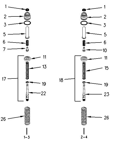
7. Use the following procedure to assemble spool assemblies (17) and (18).
Illustration 3 g00914179Note: Spool (22) is assembled in Port (1) and Port (3) in the pilot valve. Spool (23) is assembled in Port (2) and Port (4) in the pilot valve.
a. Install washer (19) on the spool.
Note: Spring (13) is installed on spool (22). Spring (15) is installed on spool (23).
b. Install spring (13) or spring (15) on the spool.
c. Put the end of the spool in the slotted opening of seat (11). Install seat (11).
Note: Spool assembly (17) is installed in Port (1) and Port (3) in the pilot valve. Spool assembly (18) is installed in Port (2) and Port (4) in the pilot valve.
8. Install spool assembly (18) in the pilot valve.
9. Install new seal (1) in plug (2).
10. Install new O-ring seal (3) on plug (2).
11. Install rod (5) in plug (2).
Note: Spring seat (7) is installed in Port (1) and Port (3) in the pilot valve. Spring seat (10) is installed in Port (2) and Port (4) in the pilot valve.
12. Install spring (6) and the correct spring seat in rod (5).
Note: Make sure that spring seat (7) or (10) and the spring do not fall out of the rod while you install the plug.
13. Install plug (2) in the pilot valve.
14. Repeat Steps 6 through 13 in order to install the other three spool assemblies.
g00914163
15. Install plate (20) on the pilot valve.
16. Apply Tooling (B) on the threads on the upper half of U-joint (14).
17. Install plate (12) on U-joint (14).
18. Install nut (8) on U-joint (14).
19. Tighten nut (8) against plate (12).
20. Install plate (12), nut (8), and U-joint (14). Tighten U-joint (14) to a torque of 47 ± 3 N·m (35 ± 2 lb ft).
Illustration 4
Illustration 5
g01021450
21. Adjust plate (12) to dimension (A) that was recorded in the disassembly procedure.
22. Tighten nut (8) against plate (12). Tighten nut (8) to a torque of 69 ± 5 N·m (51 ± 4 lb ft).
23. Install rubber boot (4) on the pilot valve.
End By:
a. Install the pilot valve. Refer to Disassembly and Assembly, "Pilot Valve (Joystick) - Install".
Copyright 1993 - 2019 Caterpillar Inc. All Rights Reserved. Private Network For SIS Licensees.
Sun Sep 15 18:39:25 UTC+0800 2019
Shutdown SIS
Previous Screen
Product: EXCAVATOR
Model: 322C EXCAVATOR DAA
Configuration: 322C & 322C L Excavators DAA00001-UP (MACHINE) POWERED BY 3126 Engine
Disassembly and Assembly
322C Excavator Machine Systems Media
Pilot Valve (Joystick) - Install
SMCS - 5059-012
Installation Procedure
Table 1
Required Tools
Tool Part Number Part Description Qty
A FT-2674 Vacuum Cap 1
NOTICE
Care must be taken to ensure that fluids are contained during performance of inspection, maintenance, testing, adjusting, and repair of the product. Be prepared to collect the fluid with suitable containers before opening any compartment or disassembling any component containing fluids.
Refer to Special Publication, NENG2500, "Dealer Service Tool Catalog" for tools and supplies suitable to collect and contain fluids on Cat® products.
Dispose of all fluids according to local regulations and mandates.
Note: Cleanliness is an important factor. Before assembly, all parts should be thoroughly cleaned in cleaning fluid. Allow the parts to air dry. Wiping cloths or rags should not be used to dry parts Lint may be deposited on the parts which may cause later trouble. Inspect all parts. If any parts are worn or damaged, use new parts for replacement.
Illustration 1
g00690963
1. Remove the cap from the hydraulic tank. Attach Tooling (A) to the hydraulic tank.
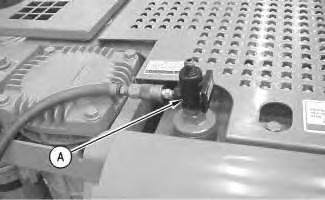
Note: Hook up the air to Tooling (A) in order to create a vacuum in the hydraulic system. This will minimize the leakage from the hose assemblies.
Illustration 2
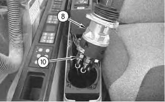
2. Place pilot valve (8), as shown.
g00706668
3. Connect hose assemblies (10) to pilot valve (8).
4. Remove Tooling (A).
Illustration 3
g00706661
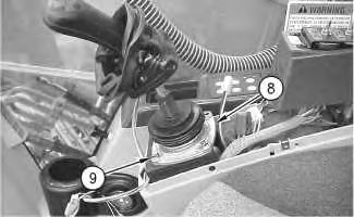
5. Place pilot valve (8) in position, as shown. Install bolts (9) to pilot valve (8).
Illustration 4
g00739116
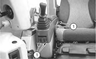
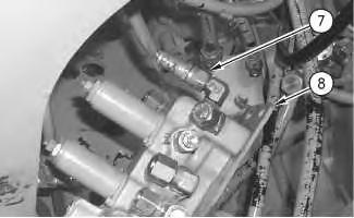
6. Connect harness assemblies (7) to the joystick.
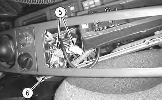
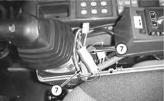
Illustration 5
g00739111
7. Place cover (6) over the joystick, as shown.
8. Connect harness assemblies (5).
9. Install high efficiency filters in place of the pilot filter, the filter for the case drain, and the return filter.
Note: High efficiency filters should not be run for more than 250 hours before you change back to the standard filters.
10. Fill the hydraulic oil tank with clean hydraulic oil to the correct level. Refer to Operation and Maintenance Manual, "Lubricant Viscosities" for the proper oil viscosity and refer to Operation and Maintenance Manual, "Hydraulic System Oil Level - Check" for the correct filling procedures.
11. Install the cap to the hydraulic tank.
12. Start the engine, and check the operation of the joystick. Also, check for leaks. Stop the engine.
13. Place cover (6) on the console if the joystick operated properly and no leaks were present.
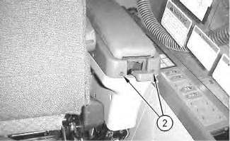
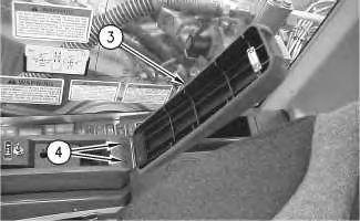
Illustration 6
14. Install armrest (3). Install screws (4).
15. Install screws (2) to the rear of the console.
 g00739106
Illustration 7
g00739101
Illustration 8
g00739085
g00739106
Illustration 7
g00739101
Illustration 8
g00739085
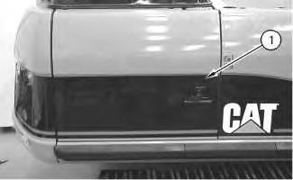
16. Install screws (1). Install the cover over screws (1).
17. Obtain a hydraulic oil sample from the main S·O·S port. Refer to Operation and Maintenance Manual, "Sampling Interval and Location of Sampling Valve" for the correct location.
18. If the S·O·S sample exceeds ISO 18/15, flush the hydraulic system. Refer to Contamination Control Guidelines, SEBF8436, "Hydraulic System Flushing Procedure for 320C Hydraulic Excavators" for further information.
Shutdown SIS
Previous Screen
Product: EXCAVATOR
Model: 322C EXCAVATOR DAA
Configuration: 322C & 322C L Excavators DAA00001-UP (MACHINE) POWERED BY 3126 Engine
Disassembly and Assembly
322C Excavator Machine Systems
Control Manifold (Pilot Oil) - Remove
SMCS - 5059-011-M9
Removal Procedure
Table 1
Required Tools
Tool Part Number Part Description Qty
A FT-2674 Vacuum Cap 1
Start By:
A. Release the hydraulic system pressure. Refer to Disassembly and Assembly, "Hydraulic System Pressure - Release".
NOTICE
Keep all parts clean from contaminants.
Contamination of the hydraulic system with foreign material will reduce the service life of the hydraulic system components.
To prevent contaminants from entering the hydraulic system, always plug or cap the lines, fittings, or hoses as they are disconnected. Cover any disassembled components and clean them properly before assembly.
Clean the hydraulic system properly after any major component exchange or especially after a component failure, to remove any contamination.
Care must be taken to ensure that fluids are contained during performance of inspection, maintenance, testing, adjusting and repair of the product. Be prepared to collect the fluid with suitable containers before opening any compartment or disassembling any component containing fluids.
Refer to Special Publication, NENG2500, "Caterpillar Tools and Shop Products Guide" for tools and supplies suitable to collect and contain fluids on Caterpillar products.
Dispose of all fluids according to local regulations and mandates.
Personal injury can result from hydraulic oil pressure and hot oil.
Hydraulic oil pressure can remain in the hydraulic system after the engine has been stopped. Serious injury can be caused if this pressure is not released before any service is done on the hydraulic system.
Make sure all of the work tools have been lowered to the ground, and the oil is cool before removing any components or lines. Remove the oil filler cap only when the engine is stopped, and the filler cap is cool enough to touch with your bare hand.
2. Remove the cap from the hydraulic tank. Install Tooling (A) onto the hydraulic tank. Attach an air supply hose to Tooling (A) . Apply 276 to 414 kPa (40 to 60 psi) of air. This procedure will pull vacuum on the hydraulic system.
Note: A small amount of oil will drain from all of the hose assemblies when the hose assemblies are disconnected from the pilot manifold. Make sure that you contain the hydraulic oil.
3. Put identification marks on all of the hose assemblies that are connected to the pilot manifold for installation purposes.
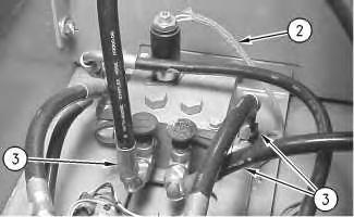
4. Disconnect harness assemblies (3) from control manifold (8) .
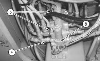
5. Disconnect hose assemblies (4) .
Note: Leave the top hose assembly connected. You will be able to remove the top hose assembly, when the mount bolts are removed.
Illustration 2 g00690963 Illustration 3 g00913460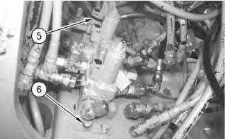
Shutdown SIS
Previous Screen
Product: EXCAVATOR
Model: 322C EXCAVATOR DAA
Configuration: 322C & 322C L Excavators DAA00001-UP (MACHINE) POWERED BY 3126 Engine
Disassembly and Assembly
322C Excavator Machine Systems
Control Manifold (Pilot Oil) - Remove - NFC Limit Valve
SMCS - 5059-011-M9
Removal Procedure Table 1
Required Tools
Tool Part Number Part Description Qty
A FT-2674 Vacuum Cap 1
Start By:
a. Release the hydraulic system pressure. Refer to Disassembly and Assembly, "Hydraulic System Pressure - Release".
NOTICE
Keep all parts clean from contaminants.
Contamination of the hydraulic system with foreign material will reduce the service life of the hydraulic system components.
To prevent contaminants from entering the hydraulic system, always plug or cap the lines, fittings, or hoses as they are disconnected. Cover any disassembled components and clean them properly before assembly.
Clean the hydraulic system properly after any major component exchange or especially after a component failure, to remove any contamination.
Care must be taken to ensure that fluids are contained during performance of inspection, maintenance, testing, adjusting, and repair of the product. Be prepared to collect the fluid with suitable containers before opening any compartment or disassembling any component containing fluids.
Refer to Special Publication, NENG2500, "Dealer Service Tool Catalog" for tools and supplies suitable to collect and contain fluids on Cat® products.
Dispose of all fluids according to local regulations and mandates.
At operating temperature, the hydraulic oil is hot and under pressure. Hot oils can cause burns.
To prevent possible personal injury, release the pressure in the work tool hydraulic circuit (boom, stick, bucket, and swing), travel circuits, and the hydraulic oil tank at the filler cap before any hydraulic lines or components are disconnected or removed.
Remove the filler cap only when the engine is stopped and the filler cap is cool enough to touch.
2. Remove the cap from the hydraulic tank. Install Tooling (A) onto the hydraulic tank. Attach an air supply hose to Tooling (A). Apply 276 to 414 kPa (40 to 60 psi) of air. This procedure will pull vacuum on the hydraulic system.
Note: A small amount of oil will drain from all of the hose assemblies when the hose assemblies are disconnected from the pilot valve. Make sure that you contain the hydraulic oil.
3. Put identification marks on all of the hose assemblies and on all of the tube assemblies that are connected to the pilot valve for installation purposes.
Illustration 2
g00690963
Illustration 3
g00690992
4. Disconnect harness assembly (2) and hose assemblies (3).
Suggest:
If the above button click is invalid.
Please download this document first, and then click the above link to download the complete manual.
Thank you so much for reading

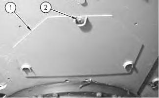
5. Remove bolts (4) in order to remove access cover (5) that is under the main hydraulic pump.
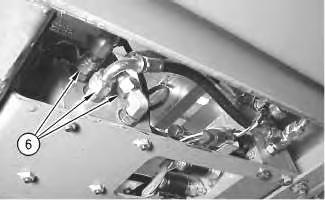
6. Disconnect hose assemblies (6).
6
7. Remove bolts (7) in order to remove control manifold (8).
Copyright 1993 - 2019 Caterpillar Inc.
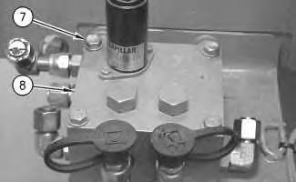 Illustration 4 g00690957
Illustration 5 g00691042
Illustration
g00691014
Illustration 4 g00690957
Illustration 5 g00691042
Illustration
g00691014