
Service Repair Manual Model
321D LCR EXCAVATOR
Previous Screen
Product: EXCAVATOR
Model: 321D LCR EXCAVATOR PBD
Configuration: 321D LCR Excavator PBD00001-UP (MACHINE) POWERED BY C6.4 Engine
Disassembly and Assembly
C6.4 Engine for Caterpillar Built Machines
Fuel Injection Lines - Remove
SMCS - 1252-011
Removal Procedure Table 1
Required Tools
This tool can only be used one time.
NOTICE
Keep all parts clean from contaminants.
Contaminants may cause rapid wear and shortened component life.
Shutdown SIS
NOTICE
Contact with high pressure fuel may cause personal injury or death. Wait 60 seconds after the engine has stopped to allow fuel pressure to purge before any service or repair is performed on the engine fuel lines.
Care must be taken to ensure that fluids are contained during performance of inspection, maintenance, testing, adjusting and repair of the product. Be prepared to collect the fluid with suitable containers before opening any compartment or disassembling any component containing fluids.
Dispose of all fluids according to local regulations and mandates.
Note: Discard all fuel injection lines after use. Fuel injection lines must only be used one time.
Note: Before opening the fuel system, the engine must be turned off for at least one minute.
Note: Use CaterpillarElectronic Technician (ET) to verify that the fuel system pressure is at zero before opening the fuel system.
Note: Use Tooling (A) after any fuel line has been disconnected.
Note: Put identification marks on all hoses, on all hose assemblies, on all harness assemblies, and on all tube assemblies for installation purposes. Plug all hose assemblies and all tube assemblies. This helps to prevent fluid loss, and this helps to keep contaminants from entering the system.
Contact with high pressure fuel may cause fluid penetration and burn hazards. High pressure fuel spray may cause a fire hazard. Failure to follow these inspection, maintenance and service instructions may cause personal injury or death.
Illustration 1 g01375415
2. Remove bolt (4) in order to remove tube assembly (5) and the O-ring seal.
3. Remove bolts (6) and reposition fuel priming pump (7) .

4. Disconnect harness assembly (1) .
5. Remove clip (2) .
6. Remove two bolts (3) (not shown) and reposition fuel filter base (8) .
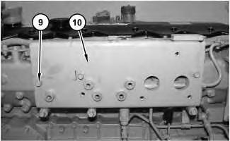
Illustration 2 g01375416
7. Remove bolts (9) in order to remove plate assembly (10) .
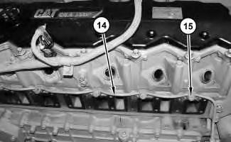
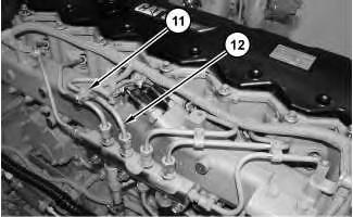
8. Remove clips (11) .
9. Remove fuel injection lines (12) and discard fuel injection lines (12) .
10. The following Steps are for removing the fuel return line, if necessary.
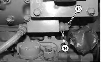
a. Remove bolt (13) and the washers in order to disconnect tube assembly (14) . Discard the washers.
Illustration 3 g01832093 Illustration 4 g01832094The inlet manifold was removed for photographic purposes.
b. Remove bolts (15) and the washers. Discard the washers. Remove tube assembly (14) .
Copyright 1993 - 2019 Caterpillar Inc. All Rights Reserved. Private Network For SIS Licensees.
Fri Oct 11 07:24:27 UTC+0800 2019
Previous Screen
Product: EXCAVATOR
Model: 321D LCR EXCAVATOR PBD
Configuration: 321D LCR Excavator PBD00001-UP (MACHINE) POWERED BY C6.4 Engine
Disassembly and Assembly
C6.4 Engine for Caterpillar Built Machines
Fuel Injection Lines - Install
SMCS - 1252-012
Installation Procedure
NOTICE
Keep all parts clean from contaminants.
Contaminants may cause rapid wear and shortened component life.
1. Steps 1.a through 1.b are for installing the return fuel line, if necessary.
Shutdown SIS
a. Install tube assembly (14) . Install new washers and bolts (15) . Tighten bolts (15) to a torque of 15 ± 2 N·m (11 ± 1 lb ft).
b. Connect tube assembly (14) . Install new washers and bolt (13) . Tighten bolt (13) to a torque of 34 ± 4 N·m (25 ± 3 lb ft).
2. Install new fuel injection lines (12) . Tighten the ends of fuel injection lines (12) to a torque of 41 ± 5 N·m (30 ± 4 lb ft).
3. Install clips (11) .
Illustration 2
g01832094
Illustration 3
g01832093
Illustration 4
4. Position plate assembly (10) and install bolts (9) .
Illustration 5 g01375415
5. Position fuel filter base (8) and install two bolts (3) (not shown).
6. Install clip (2) .
7. Connect harness assembly (1) .
8. Position fuel priming pump (7) and install bolts (6) .
9. Install the O-ring seal onto tube assembly (5) . Install tube assembly (5) and install bolt (4) .
10. Turn the fuel supply to the ON position.
Copyright 1993 - 2019 Caterpillar Inc.
Previous Screen
Product: EXCAVATOR
Model: 321D LCR EXCAVATOR PBD
Configuration: 321D LCR Excavator PBD00001-UP (MACHINE) POWERED BY C6.4 Engine
Disassembly and Assembly
C6.4 Engine for Caterpillar Built Machines
Fuel Manifold (Rail) - Remove
SMCS - 1702-011
Removal Procedure
Start By:
a. Remove the fuel injection lines. Refer to Disassembly and Assembly, "Fuel Injection Lines - Remove".
NOTICE
Contact with high pressure fuel may cause personal injury or death. Wait 60 seconds after the engine has stopped to allow fuel pressure to purge before any service or repair is performed on the engine fuel lines.
NOTICE
Keep all parts clean from contaminants.
Contaminants may cause rapid wear and shortened component life.
Care must be taken to ensure that fluids are contained during performance of inspection, maintenance, testing, adjusting and repair of the product. Be prepared to collect the fluid with suitable containers before opening any compartment or disassembling any component containing fluids.
Dispose of all fluids according to local regulations and mandates.
NOTICE
Fuel injection lines MUST only be used once. Discard all fuel injection lines after use.

Contact with high pressure fuel may cause fluid penetration and burn hazards. High pressure fuel spray may cause a fire hazard. Failure to follow these inspection, maintenance and service instructions may cause personal injury or death.
Note: Put identification marks on all hoses, on all hose assemblies, on all harness assemblies, and on all tube assemblies for installation purposes. Plug all hose assemblies and all tube assemblies. This helps to prevent fluid loss, and this helps to keep contaminants from entering the system.
Note: Before opening the fuel system, the engine must be turned off for at least one minute.
Note: Use Caterpillar Electronic Technician (ET) to verify that the fuel system pressure is at zero before opening the fuel system.
1. Loosen clamp (4) and disconnect hose (5).
2. Remove fitting (3).
3. Remove bolts (2) and remove fuel manifold (1).
Fri
Oct 11
Previous Screen
Product: EXCAVATOR
Model: 321D LCR EXCAVATOR PBD
Configuration: 321D LCR Excavator PBD00001-UP (MACHINE) POWERED BY C6.4 Engine
Disassembly and Assembly
C6.4 Engine for Caterpillar Built Machines
Fuel Manifold (Rail) - Install
SMCS - 1702-012
Installation Procedure
NOTICE
Keep all parts clean from contaminants.
Contaminants may cause rapid wear and shortened component life.
Shutdown SIS
End By:
a. Install the fuel injection lines. Refer to Disassembly and Assembly, "Fuel Injection LinesInstall".
Copyright 1993 - 2019 Caterpillar Inc. All Rights Reserved. Private Network For SIS Licensees.
Previous Screen
Product: EXCAVATOR
Model: 321D LCR EXCAVATOR PBD
Configuration: 321D LCR Excavator PBD00001-UP (MACHINE) POWERED BY C6.4 Engine
Disassembly and Assembly
C6.4 Engine for Caterpillar Built Machines Media
Fuel Injection Pump - Remove
SMCS - 1251-011
Removal Procedure
Table 1
Required Tools
A 278-4138 Fuel System Protection Gp (1) 1 ( 1 ) This tool can only be used one time.
Start By:
A. Remove the fan drive. Refer to Disassembly and Assembly, "Fan Drive - Remove and Install".
Note: Cleanliness is an important factor. Before you begin the removal procedure, the exterior of the components should be cleaned. Cleaning the components thoroughly will help to prevent dirt from entering the internal mechanism.
Note: Put identification marks on all hoses, on all hose assemblies, on all harness assemblies, and on all tube assemblies for installation purposes. Plug all hose assemblies and all tube assemblies. Plugging all hose assemblies helps to prevent fluid loss, and this helps to keep contaminants from entering the system.
NOTICE
Contact with high pressure fuel may cause personal injury or death. Wait 60 seconds after the engine has stopped to allow fuel pressure to purge before any service or repair is performed on the engine fuel lines.
NOTICE
Care must be taken to ensure that fluids are contained during performance of inspection, maintenance, testing, adjusting and repair of the product. Be prepared to collect the fluid with suitable containers before opening any compartment or disassembling any component containing fluids.
Dispose of all fluids according to local regulations and mandates.
NOTICE
Keep all parts clean from contaminants.
Contaminants may cause rapid wear and shortened component life.
Contact with high pressure fuel may cause fluid penetration and burn hazards. High pressure fuel spray may cause a fire hazard. Failure to follow these inspection, maintenance and service instructions may cause personal injury or death.
Note: Before opening the fuel system, the engine must be turned off for at least one minute.
Note: Use Caterpillar Electronic Technician (ET) to verify that the fuel system pressure is at zero before opening the fuel system.
Note: Use Tooling (A) after any fuel line has been disconnected.
(2) Fuel injection pump drive gear

(3) Idler gear
Note: Mark the teeth on pump drive gear (2) and idler gear (3) for installation purposes.

1. Remove cover (1) .
2. If you are reusing pump drive gear (2) , mark pump drive gear (2) and idler gear (3) .
Illustration 1 g01375105 Illustration 2 g027233123. If replacing pump drive gear (2) or a problem is encountered, align the "33" Mark on fuel injection pump drive gear (2) with the "3" Mark on idler gear (3) by rotating the engine.

Note: The No. 1 cylinder is at the top center position when the "33" Mark and the "3" Mark are in alignment.
4. Disconnect hose assembly (4) .
5. Remove nut (5) .
6. Disconnect hose assemblies (6) and remove the washers. Discard the washers.
7. Disconnect harness assembly (7) .
8. Remove tube assembly (9) and remove bracket assembly (8) .
9. Loosen clamp (12) and disconnect hose (13) .
10. Remove fitting (11) in order to disconnect tube assembly (10) and remove the washers. Discard the washers.
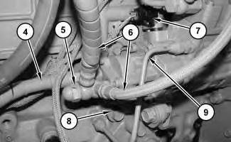 Illustration 3
g01375153
Illustration 4
g01375195
Illustration 3
g01375153
Illustration 4
g01375195
11. Remove tube assembly (14) .
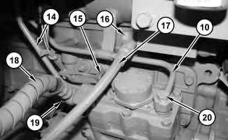
12. Disconnect harness assembly (15) .
13. Remove bolt (16) in order to remove hose assembly (17) and the washers. Discard the washers.
14. Remove bolt (19) in order to disconnect hose assembly (18) and the washers. Discard the washers.
15. Remove bolt (20) . Remove tube assembly (10) and the washers. Discard the washers.
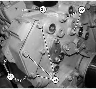
Illustration 5 g01375184 Illustration 6 g01375221 16. Remove bolts (22) .17. Remove two bolts (23) (not shown).
18. Remove bolts (24) .
19. Remove fuel injection pump (21) and the O-ring seal.
20. If you are reusing the pump drive gear, remove the pump drive gear and install the pump drive gear on the new fuel injection pump. The marks that were made during removal will be used to orient the fuel injection pump during installation. If a new gear is being used, transfer the mark from the original gear to the replacement gear for installation purposes.
Shutdown SIS
Previous Screen
Product: EXCAVATOR
Model: 321D LCR EXCAVATOR PBD
Configuration: 321D LCR Excavator PBD00001-UP (MACHINE) POWERED BY C6.4 Engine
Disassembly and Assembly
C6.4 Engine for Caterpillar Built Machines
Fuel Injection Pump - Install
SMCS - 1251-012
Installation Procedure
Note: Cleanliness is an important factor. Before assembly, thoroughly clean all parts in cleaning fluid. Allow the parts to air dry. Do not use wiping cloths or rags to dry parts. Lint may be deposited on the parts which may cause trouble. Inspect all parts. If any parts are worn or damaged, use new parts for replacement. Dirt and other contaminants can damage the precision component. Perform assembly procedures on a clean work surface. Keep components covered and protected at all times.
Note: Check the O-ring seals, the gaskets, and the seals for wear or for damage. Replace the components, if necessary.
NOTICE
Keep all parts clean from contaminants.
Contaminants may cause rapid wear and shortened component life.
Suggest:
If the above button click is invalid.
Please download this document first, and then click the above link to download the complete manual.
Thank you so much for reading

Illustration 2
(2) Fuel injection pump drive gear
(3) Idler gear
Note: Align timing marks on pump drive gear (2) and idler gear (3) that were made in the removal procedure
1. Position the O-ring seal and fuel injection pump (21) .

2. If you are reusing pump drive gear (2) , align the marks on pump drive gear (2) and idler gear (3) .
Illustration 1
g01375221
g02723322