Service Repair Manual Model 321C EXCAVATOR
Previous Screen
Product: EXCAVATOR
Model: 321C EXCAVATOR DAX
Configuration: ISJ HEX COMMONALITY CHART DAX00001-UP (MACHINE)
Disassembly and Assembly
3064 and 3066 Engines for Caterpillar Built Machines
Engine Oil Filter Base - Remove
SMCS - 1306-011
Removal Procedure Table 1
Required Tools
Hot oil and components can cause personal injury.
Do not allow hot oil or components to contact skin.
Shutdown SIS
NOTICE
Keep all parts clean from contaminants.
Contaminants may cause rapid wear and shortened component life.
NOTICE
Care must be taken to ensure that fluids are contained during performance of inspection, maintenance, testing, adjusting and repair of the product. Be prepared to collect the fluid with suitable containers before opening any compartment or disassembling any component containing fluids.
Refer to Special Publication, NENG2500, "Caterpillar Tools and Shop Products Guide" for tools and supplies suitable to collect and contain fluids on Caterpillar products.
Dispose of all fluids according to local regulations and mandates.
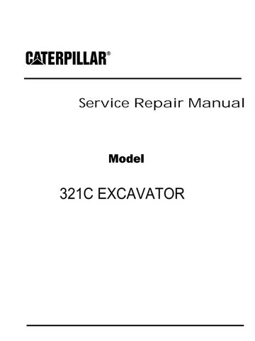
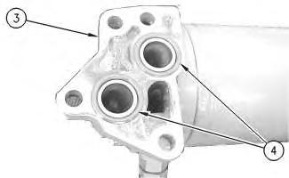
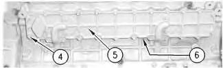
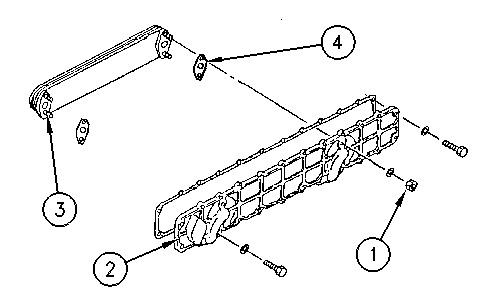
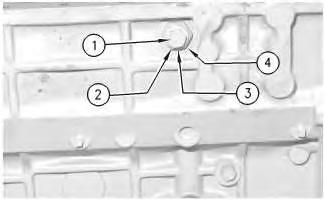
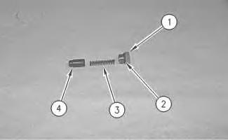
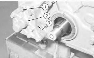
1. Use Tool (A) and remove oil filter (2) from engine oil filter base (3) .
2. Remove the bolts (1) and washers from the engine oil filter base (3) .
3. Remove engine oil filter base (3) from the engine.
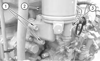 Illustration 1
g00813775
Illustration 2
g00813789
Illustration 1
g00813775
Illustration 2
g00813789
4. Check the condition of O-ring seals (4). Replace the O-ring seals, if the O-ring seals are worn or damaged.
Illustration 3
g00813823
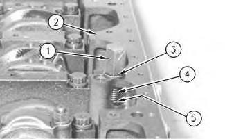
5. If necessary, remove eight bolts (6) and the washers in order to remove plate (5) from the engine.
6. Check the condition of gasket (not shown). Replace the gasket, if the gasket is worn or damaged.
7. Check engine oil filter base (3) and plate (5) for clogging and cracks. Replace damaged components with replacement parts.
Copyright 1993 - 2019 Caterpillar Inc.
Previous Screen
Product: EXCAVATOR
Model: 321C EXCAVATOR DAX
Configuration: ISJ HEX COMMONALITY CHART DAX00001-UP (MACHINE)
Disassembly and Assembly
3064 and 3066 Engines for Caterpillar Built Machines
Engine Oil Filter Base - Install
SMCS - 1306-012
Installation Procedure
NOTICE
Keep all parts clean from contaminants.
Contaminants may cause rapid wear and shortened component life.
Shutdown SIS
Illustration 1
g00813823
Illustration 2
g00813789
2. Check the condition of O-ring seals (4). Replace the O-ring seals, if the O-ring seals are damaged.
Note: Coat all of the O-ring seals with clean engine oil prior to installation.
3. Install the O-ring seals (4) on engine oil filter base (3) .
Illustration 3
g00813775
4. Secure engine oil filter base (3) to the plate (5) with four bolts (1) and the washers.
5. Install the engine oil filter (2) to the engine oil filter base (3) .
Note: Follow the installation procedure on the engine oil filter in order to install the engine oil filter on the engine oil filter base.
Copyright 1993 - 2019 Caterpillar Inc. All Rights Reserved.
Previous Screen
Product: EXCAVATOR
Model: 321C EXCAVATOR DAX
Configuration: ISJ HEX COMMONALITY CHART DAX00001-UP (MACHINE)
Disassembly and Assembly
3064 and 3066 Engines for Caterpillar Built Machines
Engine Oil Cooler - Remove
SMCS - 1378-011
Removal Procedure
Start By:
A. Remove the fuel injection pump. Refer to Disassembly and Assembly, "Fuel Injection Pump - Remove".
NOTICE
Keep all parts clean from contaminants.
Contaminants may cause rapid wear and shortened component life.
NOTICE
Care must be taken to ensure that fluids are contained during performance of inspection, maintenance, testing, adjusting and repair of the product. Be prepared to collect the fluid with suitable containers before opening any compartment or disassembling any component containing fluids.
Refer to Special Publication, NENG2500, "Caterpillar Tools and Shop Products Guide" for tools and supplies suitable to collect and contain fluids on Caterpillar products.
Dispose of all fluids according to local regulations and mandates.
Illustration 1
g00611319
1. If necessary, remove bolt (1) and the washer from the cylinder head.
2. Remove oil tube assembly (dipstick) (2) from the cylinder block.
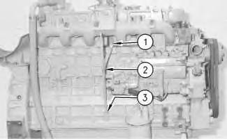
3. Check O-ring seal (3) (not shown) for wear or damage. Replace the O-ring seal, if the Oring seal is worn or damaged.
Illustration 2
g00611320
4. Remove bolts (4) and the washers that secure the oil cooler to the engine cylinder block. The 3066 Engine has 24 bolts and washers while the 3064 Engine has 16 bolts and washers.
5. Remove engine oil cooler (5) and gasket (6) (not shown) from the engine cylinder block. Check the gasket for wear or damage. Replace the gasket, if the gasket is worn or damaged.
Note: Check the oil cooler cover for cracks. Replace the cover, if the cover is cracked.
Copyright 1993 - 2019 Caterpillar Inc.
Previous Screen
Product: EXCAVATOR
Model: 321C EXCAVATOR DAX
Configuration: ISJ HEX COMMONALITY CHART DAX00001-UP (MACHINE)
Disassembly and Assembly
3064 and 3066 Engines for Caterpillar Built Machines
Engine Oil Cooler - Disassemble
SMCS - 1378-015
Disassembly Procedure
Start By:
A. Remove the oil cooler. Refer to Disassembly and Assembly, "Engine Oil Cooler - Remove".
NOTICE
Keep all parts clean from contaminants.
Contaminants may cause rapid wear and shortened component life.
NOTICE
Care must be taken to ensure that fluids are contained during performance of inspection, maintenance, testing, adjusting and repair of the product. Be prepared to collect the fluid with suitable containers before opening any compartment or disassembling any component containing fluids.
Refer to Special Publication, NENG2500, "Caterpillar Tools and Shop Products Guide" for tools and supplies suitable to collect and contain fluids on Caterpillar products.
Dispose of all fluids according to local regulations and mandates.
1. Remove four nuts (1) and the washers from the oil cooler core (3) .
2. Remove oil cooler core (3) from oil cooler cover (2) .
Note: Check the engine oil cooler core for cracks, clogging, and ruptures.
3. Remove two gaskets (4) from the oil cooler core. Check the gasket for wear or damage. Replace the gaskets, if necessary.
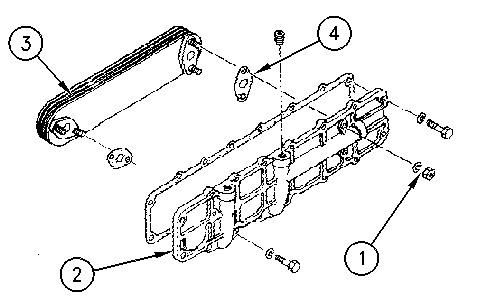 Illustration 1
g00618921
Illustration 2
g00611507
Illustration 1
g00618921
Illustration 2
g00611507
Previous Screen
Product: EXCAVATOR
Model: 321C EXCAVATOR DAX
Configuration: ISJ HEX COMMONALITY CHART DAX00001-UP (MACHINE)
Disassembly and Assembly
3064 and 3066 Engines for Caterpillar Built Machines
Engine Oil Cooler - Assemble
SMCS - 1378-016
Assembly Procedure
NOTICE
Keep all parts clean from contaminants.
Contaminants may cause rapid wear and shortened component life.
Shutdown SIS
1. Install two gaskets (4) onto the oil cooler core (3) .
2. Install the oil cooler cover (2) onto the oil cooler core (3) .
3. Install four nuts (1) and the washers, which secure the oil cooler core to the oil cooler cover.
4. Tighten the four nuts (1) .
End By: Install the oil cooler. Refer to Disassembly and Assembly, "Engine Oil Cooler - Install".
Copyright 1993 - 2019 Caterpillar Inc.
All Rights Reserved.
Private Network For SIS Licensees.
Previous Screen
Product: EXCAVATOR
Model: 321C EXCAVATOR DAX
Configuration: ISJ HEX COMMONALITY CHART DAX00001-UP (MACHINE)
Disassembly and Assembly
3064 and 3066 Engines for Caterpillar Built Machines
Engine Oil Cooler - Install
SMCS - 1378-012
Installation Procedure
NOTICE
Keep all parts clean from contaminants.
Contaminants may cause rapid wear and shortened component life.
Shutdown SIS
1. Install engine oil cooler (5) and new gasket (6) (not shown). Ensure that all mating surfaces are clean. Install bolts (4) and washers in order to secure the engine oil cooler to the engine cylinder block. The 3066 Engine has 24 bolts and washers while the 3064 Engine has 16 bolts and washers.
g00611319
2. Install oil tube assembly (dipstick) (2) into the cylinder block.
Note: Apply clean engine oil to the O-ring seal (3) (not shown) before installation.
3. Install bolt (1) and the washer into the cylinder head.
End By: Install the fuel injection pump. Refer to Disassembly and Assembly, "Fuel Injection Pump - Install". Copyright 1993 - 2019 Caterpillar Inc. All
Previous Screen
Product: EXCAVATOR
Model: 321C EXCAVATOR DAX
Configuration: ISJ HEX COMMONALITY CHART DAX00001-UP (MACHINE)
Disassembly and Assembly
3064 and 3066 Engines for Caterpillar Built Machines
Engine Oil Relief Valve - Remove and Install
SMCS - 1315-010
Removal Procedure
NOTICE
Keep all parts clean from contaminants.
Contaminants may cause rapid wear and shortened component life.
Shutdown SIS
Illustration 1
g00607236
Illustration 2
g00607247
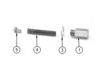
1. Remove threaded plug (1) and the shim (2) for the engine oil relief valve from the right side of the cylinder block.
2. Remove the spring (3) and spring seat (4) from the cylinder block.
Note: Check the spring seat (4) and the valve seat for an abnormal contact pattern. Inspect the spring (3) for weakness or damage. If necessary, replace the engine oil relief valve with a new part.
Note: Check the cylinder block for oil passages that are clogged.
Installation Procedure
NOTICE
Keep all parts clean from contaminants.
Contaminants may cause rapid wear and shortened component life.
g00607236
1. Install spring seat (4) and spring (3) in the cylinder block.
2. Install shim (2) and threaded plug (1) in the cylinder block.
3. Tighten threaded plug (1) of the engine oil relief valve to a torque of 49 ± 5 N·m (36 ± 4 lb ft).
Note: Test the opening pressure for the engine oil relief valve. The opening pressure for the relief valve is 343 ± 20 kPa (50 ± 3 psi). Make adjustments by shimming, if necessary.
For more information, refer to Specifications, "Engine Oil Relief Valve".
Shutdown SIS
Previous Screen
Product: EXCAVATOR
Model: 321C EXCAVATOR DAX
Configuration: ISJ HEX COMMONALITY CHART DAX00001-UP (MACHINE)
Disassembly and Assembly
3064 and 3066 Engines for Caterpillar Built Machines
Engine Oil Bypass Valve - Remove and Install
SMCS - 1306-010-BV
Removal Procedure
Start By:
A. Remove the engine oil pan. Refer to Disassembly and Assembly, "Engine Oil Pan - Remove and Install".
NOTICE
Keep all parts clean from contaminants.
Contaminants may cause rapid wear and shortened component life. Illustration
g00607679
Illustration 2
1. Remove threaded plug (1) for the engine oil bypass valve from the cylinder block (2) .
2. Remove shim (3) from the cylinder block (2) .
3. Remove spring (4) from the cylinder block (2) .
4. Remove spring seat (5) from the cylinder block (2) .
Note: Check the spring seat (5) and the valve seat for an abnormal contact pattern. Inspect the spring (4) for weakness or damage. If necessary, replace the engine oil bypass valve with a new part.
Note: Check the cylinder block (2) for oil passages that are clogged.
Installation Procedure NOTICE
Keep all parts clean from contaminants.
Contaminants may cause rapid wear and shortened component life.
g00607688
g00607679
1. Install spring seat (5) (not shown) and spring (4) in the cylinder block (2) .
2. Install shim (3) and threaded plug (1) in the cylinder block (2) .
3. Tighten the threaded plug (1) to a torque of 69 ± 5 N·m (51 ± 4 lb ft).
Note: Test the opening pressure for the engine oil relief valve. The opening pressure for the relief valve is 981 ± 98 kPa (142 ± 14 psi). Make adjustments by shimming, if necessary.
For information on testing the engine oil relief valve, refer to Testing and Adjusting, "Lubrication System".
For more information, refer to Specifications, "Engine Oil Bypass Valve".
End By: Install the engine oil pan. Refer to Disassembly and Assembly, "Engine Oil PanRemove and Install".
Copyright 1993 - 2019 Caterpillar Inc.
Illustration 3 Illustration 4Shutdown SIS
Previous Screen
Product: EXCAVATOR
Model: 321C EXCAVATOR DAX
Configuration: ISJ HEX COMMONALITY CHART DAX00001-UP (MACHINE)
Disassembly and Assembly
3064 and 3066 Engines for Caterpillar Built Machines
Engine Oil Pump - Remove
SMCS - 1304-011
Removal Procedure Table 1
Required Tools
Start By:
A. Remove the front housing. Refer to Disassembly and Assembly, "Housing (Front)Remove".
NOTICE
Keep all parts clean from contaminants.
Contaminants may cause rapid wear and shortened component life.
NOTICE
Care must be taken to ensure that fluids are contained during performance of inspection, maintenance, testing, adjusting and repair of the product. Be prepared to collect the fluid with suitable containers
before opening any compartment or disassembling any component containing fluids.
Refer to Special Publication, NENG2500, "Caterpillar Tools and Shop Products Guide" for tools and supplies suitable to collect and contain fluids on Caterpillar products.
Dispose of all fluids according to local regulations and mandates.
Note: Illustration 1 does not show that the front housing is removed from the cylinder block.
1. Remove bolt (1) from the cover (2) .
2. Remove cover (2) for the engine oil pump from the front housing. Check gasket (3) (not shown) for damage or wear. Replace the gasket, if the gasket is worn or damaged.
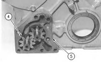 Illustration 1 g00607826
Illustration 2 g00607770
Illustration 1 g00607826
Illustration 2 g00607770
3. Remove driven gear (4) for the oil pump. Pull the gear straight out of the front housing (5) (slip fit).
Illustration 3
g00607857
4. Position the front housing on a work bench in order to remove the oil pump gear from the rear of the housing.
5. Use Tool (A) to remove oil pump gear (6) from the front housing.
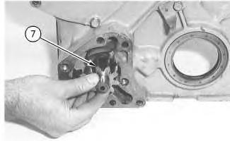
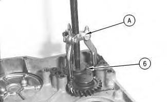
Illustration 4
g00607885
6. Position the front housing on a work bench in order to remove the drive gear from the front of the housing.
7. Remove drive gear (7) from the front housing.
Suggest:
If the above button click is invalid.
Please download this document first, and then click the above link to download the complete manual.
Thank you so much for reading

8. Use Tool (B) to remove front oil seal (8) (not shown) from the front housing.
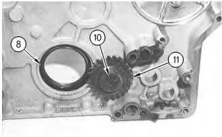
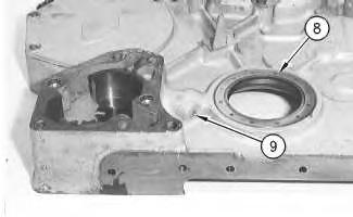
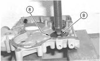
Illustration 6 g00607955
Note: Illustration 6 does not show that the front seal (8) is removed.
9. Remove set screw (9) from the front housing.
Illustration 5 g00607947 Illustration 7 g00607962