
Shutdown SIS
Previous Screen
Product: EXCAVATOR
Model: 320C EXCAVATOR GLA
Configuration: 320C, 320C L, 320C LN Excavators GLA00001-UP (MACHINE) POWERED BY 3066 Engine
Disassembly and Assembly
320C Excavator Machine Systems Media
Swing Motor - Install
SMCS - 5058-012-ZW
Installation Procedure
Table 1
Required Tools
Tool Part Number Part Description Qty
A FT-2674 Vacuum Cap 1
B 138-7573 Link Bracket 2
C 1U-8846 Gasket Sealant
NOTICE
Care must be taken to ensure that fluids are contained during performance of inspection, maintenance, testing, adjusting, and repair of the product. Be prepared to collect the fluid with suitable containers before opening any compartment or disassembling any component containing fluids.
Refer to Special Publication, NENG2500, "Dealer Service Tool Catalog" for tools and supplies suitable to collect and contain fluids on Cat® products.
Dispose of all fluids according to local regulations and mandates.
2. Apply Tooling (C) on the mating surface of the swing motor and the swing drive housing.
3. Attach Tooling (B) and a suitable lifting device to swing motor (23). The weight of swing motor (23) is approximately 55 kg (120 lb).
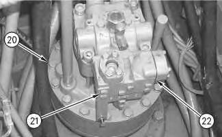
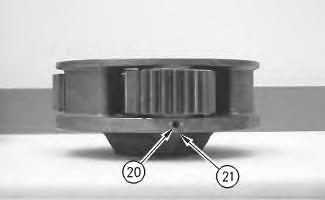
4. Install the washers and bolts (20).
5. Tighten bolts (20) to a torque of 240 ± 40 N·m (177 ± 30 lb ft).
6. Install anti-reaction valve (22). Install the washers and bolts (21). Tighten bolts (21) to a torque of 55 ± 10 N·m (40 ± 7 lb ft).
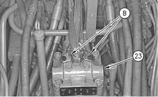 Illustration 1 g00694494
Illustration 2
g00694484
Illustration 1 g00694494
Illustration 2
g00694484
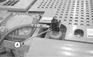
7. Remove the cap to the hydraulic tank. Attach Tooling (A) to the hydraulic tank.
Note: Hook up the air to Tooling (A) in order to create a vacuum in the hydraulic system. This will minimize the leakage from the hose assemblies.
Note: Replace the O-ring seals that are used in the ends of the hose assemblies.
10.
11.
12.
13.
14.
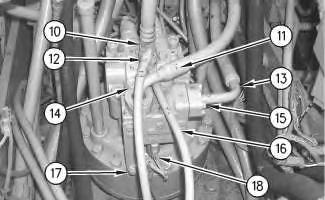 Illustration 3
g00690963
Illustration 4 g00695023
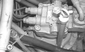
8. Connect hose assembly (19).
Illustration 5 g00694470
9. Connect hose assembly (13).
Install the split flanges, the washers and bolts (15).
Connect hose assembly (16).
Connect hose assembly (11).
Install the split flanges, the washers, and bolts (14).
Connect hose assembly (12).
Illustration 3
g00690963
Illustration 4 g00695023
8. Connect hose assembly (19).
Illustration 5 g00694470
9. Connect hose assembly (13).
Install the split flanges, the washers and bolts (15).
Connect hose assembly (16).
Connect hose assembly (11).
Install the split flanges, the washers, and bolts (14).
Connect hose assembly (12).
15. Connect hose assembly (10).
16. Connect harness assembly (18).
17. Install the clip, the washer, and bolt (17).
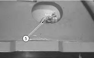
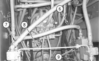
Illustration 6
Typical example
18. Connect hose assembly (7) (If Equipped).
19. Install hose assembly (6) (If Equipped).
20. Install brace (8) with washers and bolts (9) (If Equipped).
Illustration 7
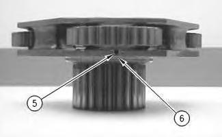
21. Make sure that the drain valve (5) is closed.
22. Remove Tooling (A) and install the cap to the hydraulic tank.
NOTICE
To avoid system damage, make sure that the hydraulic motor is properly filled with hydraulic oil before start-up.
g00694459 g0069435323. Install high efficiency filters in place of the pilot filter, the case drain filter, and the return filter.
Note: High efficiency filters should not be run for more than 250 hours before you change back to the standard filters.
24. Fill the hydraulic oil tank and the swing drive with clean hydraulic oil to the correct level.
Reference: Refer to Operation and Maintenance Manual, "Lubricant Viscosities" for the proper oil viscosity.
Reference: Refer to Operation and Maintenance Manual, "Hydraulic System Oil LevelCheck" and Operation and Maintenance Manual, "Swing Drive Oil Level - Check" for the correct filling procedures.
25. Start the engine, and check the operation of the swing drive. Also, check for leaks. Stop the engine.
26. Obtain a hydraulic oil sample from the main S·O·S port.
Reference: Refer to Operation and Maintenance Manual, "Sampling Interval and Location of Sampling Valve" for the correct location.
27. If the S·O·S sample exceeds ISO 18/15, flush the hydraulic system.
Reference: Refer to Contamination Control Guidelines, SEBF8436, "Hydraulic System Flushing Procedure for 320C Hydraulic Excavators" for further information.
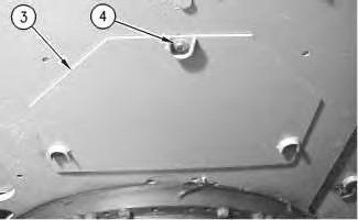
28. Install the washers and bolts (4) in order to install access cover (3) that is under the main control valve.
Illustration 8 g00694245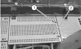
Shutdown SIS
Previous Screen
Product: EXCAVATOR
Model: 320C EXCAVATOR GLA
Configuration: 320C, 320C L, 320C LN Excavators GLA00001-UP (MACHINE) POWERED BY 3066 Engine
Disassembly and Assembly
320C Excavator Machine Systems Media
Swing Drive - Remove
SMCS - 5459-011
Removal Procedure Table 1
Required Tools
Start By:
a. Remove the swing motor. Refer to Disassembly and Assembly, "Swing Motor - Remove" in this manual.
NOTICE
Keep all parts clean from contaminants.
Contamination of the hydraulic system with foreign material will reduce the service life of the hydraulic system components.
To prevent contaminants from entering the hydraulic system, always plug or cap the lines, fittings, or hoses as they are disconnected. Cover any disassembled components and clean them properly before assembly.
Clean the hydraulic system properly after any major component exchange or especially after a component failure, to remove any contamination.
NOTICE
Care must be taken to ensure that fluids are contained during performance of inspection, maintenance, testing, adjusting, and repair of the product. Be prepared to collect the fluid with suitable containers before opening any compartment or disassembling any component containing fluids.
Refer to Special Publication, NENG2500, "Dealer Service Tool Catalog" for tools and supplies suitable to collect and contain fluids on Cat® products.
Dispose of all fluids according to local regulations and mandates.
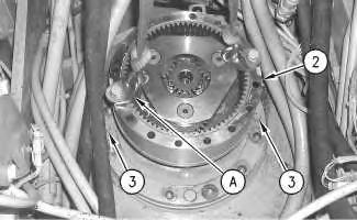
1. Thoroughly clean the area around the swing drive prior to removal.
2. Put identification marks on the swing drive in order to mark the drive's location for installation purposes.
Note: It may be necessary to remove the drain hose for the swing drive in order to access the mount bolts in the rear of the drive.
3. Remove bolts (1) and the washers that secure the swing drive to the main frame.
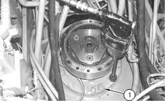 Illustration 1
g00694361
Illustration 1
g00694361
Illustration 2
g00694371
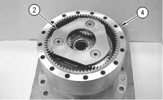
4. Attach Tooling (A) and a suitable lifting device to swing drive (2), as shown.
5. Remove corks (3) from the threaded holes in the swing drive housing.
Illustration 3
g01023898
6. Install Tooling (B) in each threaded hole in the swing drive housing.
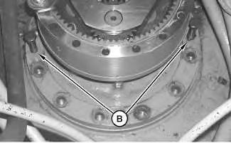
7. Slowly tighten one forcing screw for no more than two turns, and then tighten the other forcing screw for no more than two turns. At the same time keep tension on the swing drive with the hoist. Tighten the forcing screws evenly in this manner in order to separate the swing drive from the main frame.
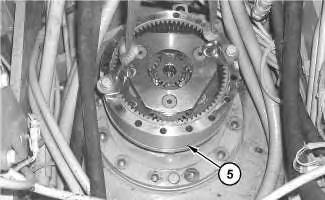
8. Remove swing drive (5) from the machine. The weight of swing drive (5) is approximately 190 kg (420 lb).
Copyright 1993 - 2019 Caterpillar Inc. All Rights Reserved. Private Network For SIS Licensees.
Sat Sep 21 23:46:36 UTC+0800 2019
Previous Screen
Product: EXCAVATOR
Model: 320C EXCAVATOR GLA
Configuration: 320C, 320C L, 320C LN Excavators GLA00001-UP (MACHINE) POWERED BY 3066 Engine
Disassembly and Assembly
320C Excavator Machine Systems Media
Swing Drive - Disassemble
SMCS - 5459-015
Disassembly Procedure
Table 1
Required Tools
Start By:
a. Remove the swing drive. Refer to Disassembly and Assembly, "Swing Drive - Remove" for the machine that is being serviced.
Note: Cleanliness is an important factor. Before the disassembly procedure, the exterior of the component should be thoroughly cleaned. This will prevent dirt from entering the internal mechanism.
NOTICE
Keep all parts clean from contaminants.
Contamination of the hydraulic system with foreign material will reduce the service life of the hydraulic system components.
To prevent contaminants from entering the hydraulic system, always plug or cap the lines, fittings, or hoses as they are disconnected. Cover
any disassembled components and clean them properly before assembly.
Clean the hydraulic system properly after any major component exchange or especially after a component failure, to remove any contamination.
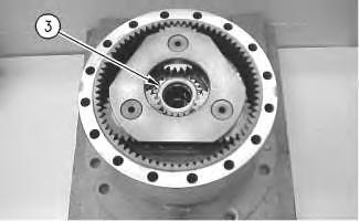
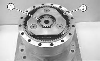 Illustration 1 g00702449
1. Remove sun gear (1) from carrier assembly (2).
Illustration 2 g00702450
2. Remove spacer (3) from the carrier assembly.
Illustration 1 g00702449
1. Remove sun gear (1) from carrier assembly (2).
Illustration 2 g00702450
2. Remove spacer (3) from the carrier assembly.
Illustration 3 g00702451
3. Remove carrier assembly (2) from ring gear (4).
Illustration 4 g00702452
4. Drive roll pin (5) into shaft (6). Remove shaft (6) and the gear assembly from the carrier assembly.
Illustration 5 g00702456
5. Disassemble the gear assembly, as follows: washer (7), gear (8), bearing (9), and washer (10). Remove roll pin (5) from shaft (6).
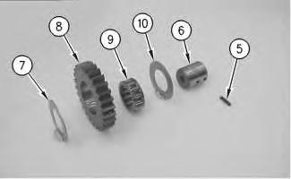
6. Repeat Step 4 through Step 5 for the remaining gear assemblies.
Illustration 6 g00702457
7. Remove retaining ring (11) from sun gear (12). Remove carrier (13) from the sun gear.
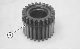
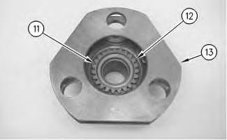
Illustration 7 g00702459
8. Remove retaining ring (14) from the sun gear.
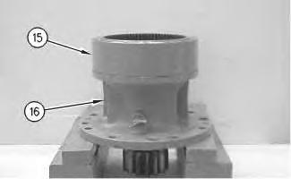
Illustration 8 g00702583
9. Use two people in order to remove ring gear (15) from housing (16). Weight of ring gear (15) is approximately 29 kg (65 lb).
Illustration 9 g00702584
10. Remove spacer (17) from carrier assembly (18).
Illustration 10 g00702596
11. Use Tooling (A) to remove retaining ring (19).
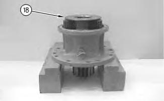
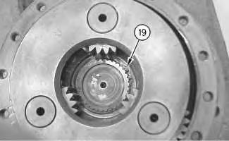
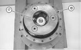
Illustration 11 g00702611
12. Remove carrier assembly (18) from the housing.
Illustration 12
g00702640
13. Drive roll pin (20) into shaft (21). Remove shaft (21) and the gear assembly from the carrier assembly.
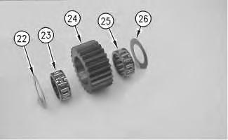
Illustration 13
g00702648
14. Disassemble the gear assembly, as follows: washer (22), bearing (23), gear (24), bearing (25), and washer (26). Remove roll pin (20) from shaft (21).
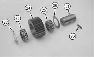
15. Repeat Step 13 through Step 14 for the remaining gear assemblies.
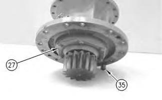
Illustration 14
g00702659
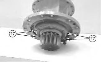
16. Remove four bolts (27) from the housing.
Note: Do not remove the other two bolts (27) at this time. These two bolts (27) will be used to transport the assembly to the press.
17. Remove remaining bolts (27). Use a suitable press in order to remove shaft (28) from the housing. Remove cage (29) from the housing.
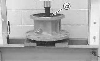
Note: The bearing may come off with the pinion or the bearing may stay in the housing.
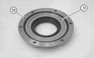
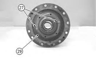 Illustration 15 g00703241
Illustration 16 g00702664
Illustration 15 g00703241
Illustration 16 g00702664
Illustration 17 g00703242
18. Remove O-ring seal (30) from the cage. Remove lip type seals (31) from the cage.
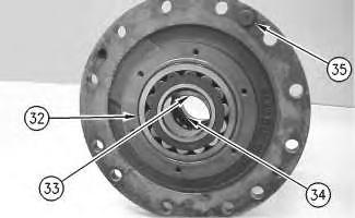
Illustration 18 g00703246
Illustration 19 g00703247
19. Use a suitable press and Tooling (B) in order to remove bearing (34), spacer (33), and bearing (32) from the housing. Remove alignment pin (35) from the housing.
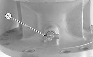
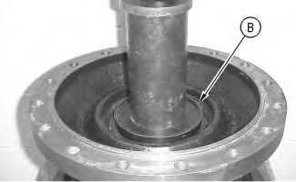
Illustration 20 g00703249
Previous Screen
Product: EXCAVATOR
Model: 320C EXCAVATOR GLA
Configuration: 320C, 320C L, 320C LN Excavators GLA00001-UP (MACHINE) POWERED BY 3066 Engine
Disassembly and Assembly
320C Excavator Machine Systems
Swing Drive - Assemble
SMCS - 5459-016
Assembly Procedure
Note: Cleanliness is an important factor. Before assembly, all parts should be thoroughly cleaned in cleaning fluid. Allow the parts to air dry. Wiping cloths or rags should not be used to dry parts. Lint may be deposited on the parts which may cause later trouble. Inspect all parts. If any parts are worn or damaged, use new parts for replacement. All disassembly and all assembly procedures must be performed on a clean work surface and in a clean hydraulic area. Keep cleaned parts covered and protected at all times.
Note: O-rings, gaskets, and seals should always be replaced. A used O-ring may not have the same sealing properties as a new O-ring. Use Tooling (D) during the assembly procedure.
Note: Apply a light film of hydraulic oil to all components before assembly.
Illustration 1
1. Install drain valve (36) into the housing.
Illustration 2
2. Install O-ring seal (30) into the cage. Install lip type seals (31) into the cage.
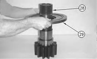
Illustration 3
3. Install cage (29) onto shaft (28).
4. Raise the temperature of bearing (32) to 135 °C (275 °F). Install bearing (32) onto shaft (28).
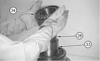
5. Install spacer (33) onto shaft (28). Install spacer (33) with relief against bearing (32).
6. Raise the temperature of bearing (34) to 135 °C (275 °F). Install bearing (34) onto shaft (28) against spacer (33).
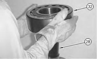 Illustration 4
g00703693
Illustration 5
g00703694
Illustration 6
g00703695
Illustration 4
g00703693
Illustration 5
g00703694
Illustration 6
g00703695
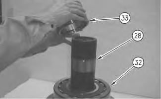
7. Place shaft assembly (28) onto a flat surface. Install Tooling (A) and a suitable lifting device onto housing (16). Apply Tooling (E) to the face of cage (29). Apply Tooling (F) to the inside diameters of the housing. Raise the temperature of housing (16) to 93 °C (200 °F). Use a suitable lifting device and lower the housing onto the shaft assembly.
8. Install bolts (27) into the housing. Install alignment pin (35) into the housing.
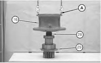 Illustration 7 g01041742
Illustration 8 g00703697
Illustration 9 g00703698
Illustration 7 g01041742
Illustration 8 g00703697
Illustration 9 g00703698
9. Assemble the gear assembly, as follows: washer (22), bearing (23), gear (24), bearing (25), and washer (26).
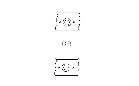
10. Use a deburring tool in order to remove the metal burr from the openings in the carrier. Install shaft (21) and the gear assembly into the carrier assembly. Drive roll pin (20) into shaft (21). Orient the split in roll pin (20) vertically to the carrier. Align the split in the roll pin to the top or to the bottom. Make a stake mark on each side of the roll pin hole in the carrier. Each stake mark should be approximately 2.25 ± 0.75 mm (0.09 ± 0.03 inch) from the outside diameter of the roll pin hole.
11. Repeat Step 9 through Step 10 for the remaining gear assemblies.
Illustration 10 g00702640
Illustration 11 g00703700
Illustration 12
Illustration 13
13. Use Tooling (B) to install retaining ring (19).
Illustration 14
14. Install spacer (17) into carrier assembly (18).
g00702611 12. Install carrier assembly (18) into the housing. g00702596 g00702584Illustration 15 g00703699
Illustration 16 g00702583
15. Apply Tooling (E) to the face of housing (16). Install Tooling (C) in order to help align the housing and the ring gear. Use two people in order to install ring gear (15) onto housing (16). Weight of ring gear (15) is approximately 29 kg (65 lb).
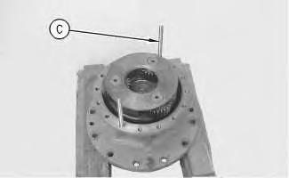
Illustration 17
16. Install retaining ring (14) into the sun gear.
g00702459
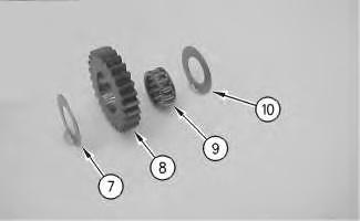 Illustration 18 g00702457
17. Install carrier (13) into the sun gear. Install retaining ring (11) into sun gear (12).
Illustration 19 g00703707
18. Assemble the gear assembly, as follows: washer (7), gear (8), bearing (9), and washer (10).
Illustration 20 g00702452
Illustration 18 g00702457
17. Install carrier (13) into the sun gear. Install retaining ring (11) into sun gear (12).
Illustration 19 g00703707
18. Assemble the gear assembly, as follows: washer (7), gear (8), bearing (9), and washer (10).
Illustration 20 g00702452
Suggest:
If the above button click is invalid.
Please download this document first, and then click the above link to download the complete manual.
Thank you so much for reading

19. Use a deburring tool in order to remove the metal burr from the openings in the carrier. Install shaft (6) and the gear assembly into the carrier assembly. Drive roll pin (5) into shaft (6). Orient the split in roll pin (5) vertically to the carrier. Align the split in the roll pin to the top or to the bottom. Make a stake mark on each side of the roll pin hole in the carrier. Each stake mark should be approximately 2.25 ± 0.75 mm (0.09 ± 0.03 inch) from the outside diameter of the roll pin hole.
20. Repeat Step 18 through Step 19 for the remaining gear assemblies.
Illustration 22
21. Install carrier assembly (2) into ring gear (4).