
Shutdown SIS
Previous Screen
Product: EXCAVATOR
Model: 320C EXCAVATOR HKT
Configuration: 320C & 320C L Excavators HKT00001-UP (MACHINE) POWERED BY 3066 Engine
Disassembly and Assembly
320C Excavator Machine Systems Media
Control Valve (Auxiliary) - Install - F1 and F4 Auxiliary Control
Valves
SMCS - 5051-012-AX
Installation Procedure Table 1
Required Tools
Tool Part Number Part Description Qty
(A) FT-2674 Vacuum Cap 1
(B) 138-7573 Link Bracket 1
NOTICE
Care must be taken to ensure that fluids are contained during performance of inspection, maintenance, testing, adjusting, and repair of the product. Be prepared to collect the fluid with suitable containers before opening any compartment or disassembling any component containing fluids.
Refer to Special Publication, NENG2500, "Dealer Service Tool Catalog" for tools and supplies suitable to collect and contain fluids on Cat® products.
Dispose of all fluids according to local regulations and mandates.
g00704077
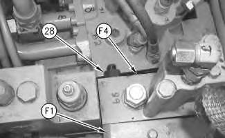
2. Fasten F1 and F4 auxiliary control valves together with the existing mount bolts. Fasten the control valves at the top with a washer and nut (28), as shown.
3. Install the F1 and F4 auxiliary control valves.
4. Lower the F1 and F4 auxiliary control valves in order to connect the hoses and electrical connections on the bottom of the auxiliary control valves.
g00690963
5. Remove the cap to the hydraulic tank. Attach Tooling (A) to the hydraulic tank.
Note: Hook up the air to Tooling (A) in order to create a vacuum in the hydraulic system. This will minimize the leakage to the hose assemblies.
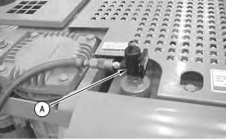 Illustration 1
Illustration 2
Illustration 1
Illustration 2
6. Connect two pilot lines (30) to the bottom of each control valve.
7. Connect one electrical connector (29) to each control valve.
8. Align the auxiliary control valves with the main control valve. Install the bottom two mount bolts (27).
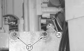
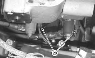
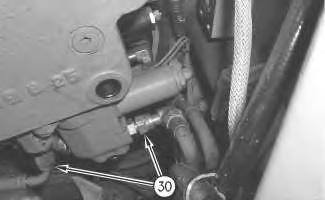 Illustration 3
9. Remove nut (28) and the washer from the top two mount bolts that pass through control valves (F1) and (F4).
10. Install the top two mount bolts.
11. Tighten the four mount bolts (27) to a torque of 240 ± 40 N·m (177 ± 30 lb ft).
12. Connect one electrical connector (26) to each control valve.
13. Remove 7X-2547 Bolt (25).
14. Remove Tooling (B) and the hoist. Install the original bolt (25).
15. Install bolts (23) in order to connect tube (24) to the (F1) control valve.
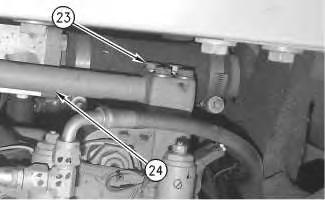
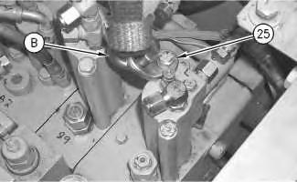 Illustration 6 g00703893
Illustration 7 g00703941
Illustration 6 g00703893
Illustration 7 g00703941
16. Install bolts (21) in order to connect tube (22) to the (F4) control valve.
17. Install bolts (19) in order to connect tube (20) to the (F4) control valve.

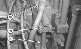
18. Connect hose assembly (18) to the (F4) control valve.
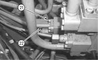 Illustration 8
g00703888
Illustration 9
g00703729
Illustration 8
g00703888
Illustration 9
g00703729
Illustration 10 g00703717
19. Connect hose assembly (17) to the (F1) control valve.
20. Connect two hose assemblies (16) to both control valves.
Illustration 11 g00703706
21. Connect three hose assemblies (15) to the (F1) control valve.
Illustration 12 g00703705
22. Install panels (14) and support (12).
23. Install the washers and bolts (13) that hold the panels and support together.
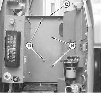
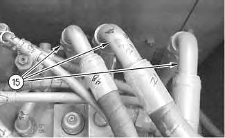
Illustration 13
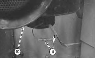
24. Install air filter (10).
25. Install the washers and bolts (9) in order to hold the air filter and the support to the machine.
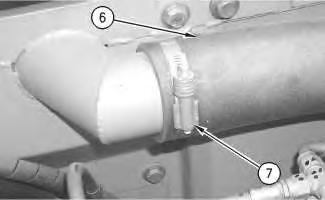
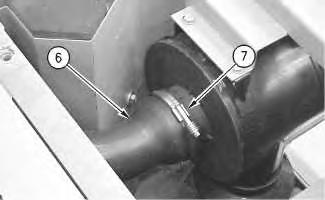
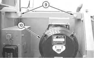
Illustration 14
Illustration 15
26. Install hose (6) and install two hose clamps (7).
g00703703 g00703690 g0070370216

27. Connect two electrical connectors (11) to the air filter. Install a new tie strap.
Illustration 17
28. Close side door (8).
Illustration 18
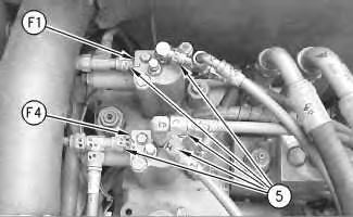
(F1) Auxiliary control valve
(F4) Auxiliary control valve
29. Install five pilot lines (5).
 Illustration
g00703704
g00792422
g00703510
Illustration
g00703704
g00792422
g00703510
30. Remove Tooling (A).
31. Install high efficiency filters in place of the pilot filter, case drain filter, and the return filter.
Note: High efficiency filters should not be run for more than 250 hours before you change back to the standard filters.
32. Fill the hydraulic oil tank and the swing drive with clean hydraulic oil to the correct level.
Reference: Refer to Operation and Maintenance Manual, "Lubricant Viscosities" for the proper oil viscosity.
Reference: Refer to Operation and Maintenance Manual, "Hydraulic System Oil LevelCheck" for the correct filling procedures.
33. Install the cap to the hydraulic tank.
34. Start the engine, and check the operation of the auxiliary attachments. Also, check for leaks. Stop the engine.
35. Obtain a hydraulic oil sample from the main S·O·S port.
Reference: Refer to Operation and Maintenance Manual, "Sampling Interval and Location of Sampling Valve" for the correct location.
36. If the S·O·S sample exceeds ISO 18/15, flush the hydraulic system.
Reference: Refer to Contamination Control Guidelines, SEBF8436, "Hydraulic System Flushing Procedure for 322C Hydraulic Excavators" for further information.
Illustration 19 g00703691
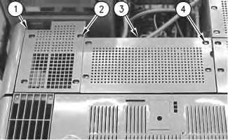
37. Install four bolts (4) and the washers in order to hold cover (3).
38. Install four bolts (2) and the washers in order to hold cover (1). Copyright 1993 - 2019 Caterpillar Inc.
Shutdown SIS
Previous Screen
Product: EXCAVATOR
Model: 320C EXCAVATOR HKT
Configuration: 320C & 320C L Excavators HKT00001-UP (MACHINE) POWERED BY 3066 Engine
Disassembly and Assembly
320C Excavator Machine Systems
Control Valve (Auxiliary) - Install - F2 and F3 Auxiliary Control Valves
SMCS - 5051-012-AX
Installation Procedure Table 1
Required Tools
Tool Part Number Part Description Qty
(A) FT-2674 Vacuum Cap 1
(B) 138-7573 Link Bracket 1
NOTICE
Keep all parts clean from contaminants.
Contamination of the hydraulic system with foreign material will reduce the service life of the hydraulic system components.
To prevent contaminants from entering the hydraulic system, always plug or cap the lines, fittings, or hoses as they are disconnected. Cover any disassembled components and clean them properly before assembly.
Clean the hydraulic system properly after any major component exchange or especially after a component failure, to remove any contamination.
i01539518
Care must be taken to ensure that fluids are contained during performance of inspection, maintenance, testing, adjusting, and repair of the product. Be prepared to collect the fluid with suitable containers before opening any compartment or disassembling any component containing fluids.
Refer to Special Publication, NENG2500, "Dealer Service Tool Catalog" for tools and supplies suitable to collect and contain fluids on Cat® products.
Dispose of all fluids according to local regulations and mandates.
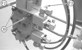
Illustration 3 g00721171
Top view of the auxiliary control valves
Illustration 4 g00721173
Bottom view of the auxiliary control valves
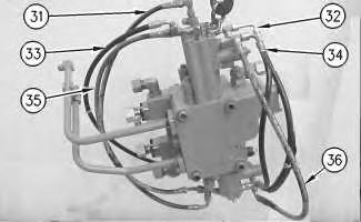
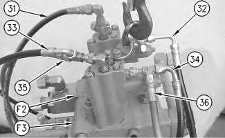
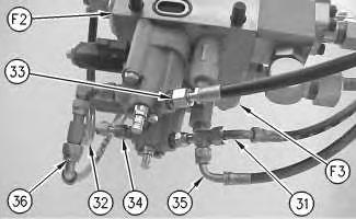
3. Pilot line (31) runs from the top of the (F2) control valve to the bottom of the (F3) control valve. Pilot line (32) runs from the top of the (F2) control valve to the bottom of the (F2) control valve. Pilot line (33) runs from the top of the (F3) control valve to the bottom of the (F2) control valve. Pilot line (34) runs from the top of the (F3) control valve to the bottom of the (F3) control valve. Pilot line (35) runs from the top of the (F3) control valve to the bottom of the (F3) control valve. Pilot line (36) runs from the top of the (F3) control valve to the bottom of the (F2) control valve.
4. Install the (F2) and (F3) auxiliary control valves.
5. Remove the cap to the hydraulic tank. Attach Tooling (A) to the hydraulic tank. Note: Hook up the air to Tooling (A) in order to create a vacuum in the hydraulic system. This will minimize the leakage to the hose assemblies.
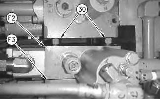
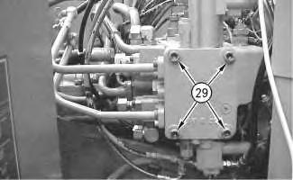 Illustration 5
g00690963
Illustration 6
g00719336
6. Align the auxiliary control valves with the main control valve. Install the bottom two mount bolts (29).
Illustration 7
g00719342
Illustration 5
g00690963
Illustration 6
g00719336
6. Align the auxiliary control valves with the main control valve. Install the bottom two mount bolts (29).
Illustration 7
g00719342
7. Remove nuts (30) and the washer from the top two mount bolts that pass through control valves (F2) and (F3).
8. Install the top two mount bolts.
9. Tighten the four mount bolts (29) to a torque of 240 ± 40 N·m (177 ± 30 lb ft).
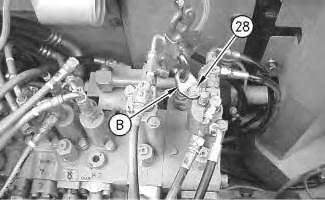
Illustration 8 g00719291
10. Remove 7X-2547 Bolt (28).
11. Remove Tooling (B) and the hoist. Install the original bolt (28).
Illustration 9 g00719289
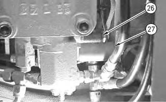
12. Connect the electrical connector to solenoid (26) and solenoid (27). Solenoid (26) is located on the bottom side of the (F2) auxiliary control valve. Solenoid (27) is located on the bottom side of the (F3) auxiliary control valve.
Illustration 10
g00719287
13. Connect pilot lines (22) and (25) to the (F2) auxiliary control valve. Connect the electrical connector to solenoid (23) and solenoid (24).
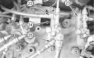
Illustration 11
g00719260
14. Connect hose assemblies (21) and (20) to the (F2) auxiliary control valve.
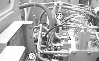
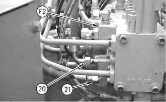
Illustration 12
g00719249
15. Connect hose assembly (19) to the (F2) auxiliary control valve.
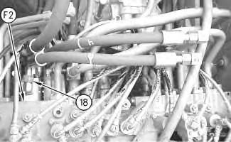
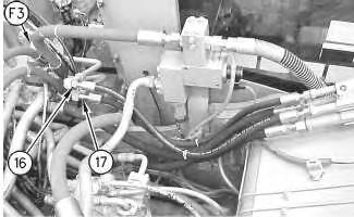
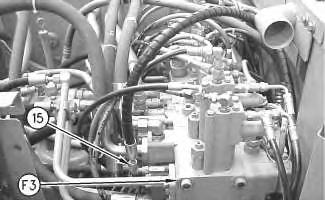 Illustration 13
Illustration 16 g00703705
19. Install support (12) and panels (14). Install bolts (13) and the washers.
20. Install air filter (10).
Illustration 17 g00703704
21. Connect two electrical connectors (11) to the air filter.

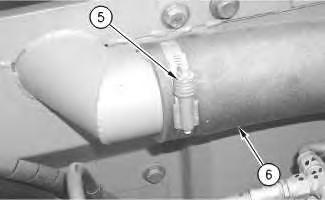 Illustration 18
g00703703
22. Install washers and bolts (9).
Illustration 19
g00799648
23. Close side door (8).
Illustration 20
g00719373
Illustration 21
g00703690
24. Install hose (6) and tighten two hose clamp (5) and (7).
Illustration 18
g00703703
22. Install washers and bolts (9).
Illustration 19
g00799648
23. Close side door (8).
Illustration 20
g00719373
Illustration 21
g00703690
24. Install hose (6) and tighten two hose clamp (5) and (7).
25. Disconnect the air to Tooling (A). Remove Tooling (A) from the hydraulic tank. Install the cap for the hydraulic tank.
26. Install high efficiency filters in place of the pilot filter, case drain filter, and the return filter.
Note: High efficiency filters should not be run for more than 250 hours before you change back to the standard filters.
27. Fill the hydraulic oil tank and the swing drive with clean hydraulic oil to the correct level.
Reference: Refer to Operation and Maintenance Manual, "Lubricant Viscosities" for the proper oil viscosity.
Reference: Refer to Operation and Maintenance Manual, "Hydraulic System Oil LevelCheck" for the correct filling procedures.
28. Install the cap to the hydraulic tank.
29. Start the engine, and check the operation of the auxiliary attachments. Also, check for leaks. Stop the engine.
30. Obtain a hydraulic oil sample from the main S·O·S port.
Reference: Refer to Operation and Maintenance Manual, "Sampling Interval and Location of Sampling Valve" for the correct location.
31. If the S·O·S sample exceeds ISO 18/15, flush the hydraulic system.
Reference: Refer to Contamination Control Guidelines, SEBF8436, "Hydraulic System Flushing Procedure for 322C Hydraulic Excavators" for further information.
Shutdown SIS
Previous Screen
Product: EXCAVATOR
Model: 320C EXCAVATOR HKT
Configuration: 320C & 320C L Excavators HKT00001-UP (MACHINE) POWERED BY 3066 Engine
Disassembly and Assembly
3064 and 3066 Engines for Caterpillar Built Machines
Fuel Priming Pump - Remove and Install
SMCS - 1258-010
Removal Procedure
NOTICE
Care must be taken to ensure that fluids are contained during performance of inspection, maintenance, testing, adjusting and repair of the product. Be prepared to collect the fluid with suitable containers before opening any compartment or disassembling any component containing fluids.
Refer to Special Publication, NENG2500, "Caterpillar Tools and Shop Products Guide" for tools and supplies suitable to collect and contain fluids on Caterpillar products.
Dispose of all fluids according to local regulations and mandates.
NOTICE
Keep all parts clean from contaminants.
Contaminants may cause rapid wear and shortened component life.
1. Remove banjo bolt (1) and washers (2) (not shown) from the fuel priming pump in order to remove fuel outlet line (3) .
Note: Cap all openings or plug all openings immediately in order to prevent contamination of the fuel system.
2. Loosen hose clamp (4) in order to remove fuel supply line (5) .
Note: Cap all openings or plug all openings immediately in order to prevent contamination of the fuel system.
3. Remove nuts (6) that secure the fuel priming pump to the fuel injection pump.
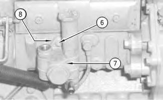
Note: Fuel will drain from the fuel priming pump during removal. Collect the fuel in a suitable container for storage or for disposal.
4. Remove fuel priming pump (7) and the O-ring (8) (not shown).
Note: Cap all openings or plug all openings immediately in order to prevent contamination of the fuel system.
Illustration 1 g00606436 Illustration 2 g00606441Note: Check the O-ring (8) (not shown) for wear or damage. Replace a worn O-ring or a damaged O-ring with a new replacement part.
1. Place the O-ring (8) (not shown) and place the fuel priming pump (7) in position on the fuel injection pump.
2. Install nuts (6) that secure the fuel priming pump to the fuel injection pump.
3. Connect fuel supply line (5) and hose clamp (4) to the fuel priming pump.
4. Tighten the hose clamps.
Note: Check the washers (2) (not shown) for wear or damage. Replace a worn washer or a damaged washer with a new replacement part.
5. Secure the fuel outlet line (3) and the washers (2) (not shown) to the fuel priming pump with banjo bolt (1) .
6. Tighten banjo bolt (1) to a torque of 20 to 25 N·m (15 to 18 lb ft).
Illustration 3 g00606441 Illustration 4 g00606436Previous Screen
Product: EXCAVATOR
Model: 320C EXCAVATOR HKT
Configuration: 320C & 320C L Excavators HKT00001-UP (MACHINE) POWERED BY 3066 Engine
Disassembly and Assembly
3064 and 3066 Engines for Caterpillar Built Machines
Fuel Filter Base - Remove and Install
SMCS - 1262-010
Removal Procedure
Table 1
Required Tools
Tool Part Number Part Description
A 185-3630 Strap Wrench Assembly 1
NOTICE
Keep all parts clean from contaminants.
Contaminants may cause rapid wear and shortened component life.
Shutdown SIS
NOTICE
Care must be taken to ensure that fluids are contained during performance of inspection, maintenance, testing, adjusting and repair of the product. Be prepared to collect the fluid with suitable containers before opening any compartment or disassembling any component containing fluids.
Refer to Special Publication, NENG2500, "Caterpillar Tools and Shop Products Guide" for tools and supplies suitable to collect and contain fluids on Caterpillar products.
Dispose of all fluids according to local regulations and mandates.
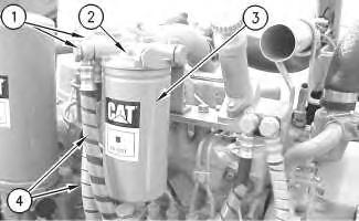
1. Use Tool (A) to remove fuel filter (3) from fuel filter base (2) .
Note: It is not necessary to remove the fuel filter in order to remove the fuel filter base.
2. Remove banjo bolts (1) and copper washers in order to disconnect the fuel lines (4) from the fuel filter base (2).
Note: Cap all openings or plug all openings immediately in order to prevent contamination of the fuel system.
3. Remove two bolts (5) and the washers that secure the fuel filter base (2) to the air inlet manifold. Remove the fuel filter base (2) from the fuel filter bracket.
Installation Procedure
 Illustration 1
g00813127
Illustration 2
g00813147
Illustration 1
g00813127
Illustration 2
g00813147
Suggest:
If the above button click is invalid.
Please download this document first, and then click the above link to download the complete manual.
Thank you so much for reading

Keep all parts clean from contaminants.
Contaminants may cause rapid wear and shortened component life.
1. Place the fuel filter base (2) in position on the fuel filter bracket. Install the washers and two bolts (5) that secure the fuel filter base tothe fuel filter bracket.
2. Install the banjo bolts (1) and install new copper washers in order to connect the fuel lines (4) to the fuel filter base (2) .
3. If the fuel filter was removed, install the fuel filter (3) to the fuel filter base (2). Tighten the fuel filter by hand according to the instructions that are shown on the fuel filter. Do not overtighten the fuel filter.