Shutdown SIS
Previous Screen
Product: MINI HYD EXCAVATOR
Model: 305E2 CR MINI HYD EXCAVATOR DJX
Configuration: 305E2 CR Mini Hydraulic Excavator DJX00001-UP (MACHINE) POWERED BY C2.4 Engine
Disassembly and Assembly
C1.7, C1.8 and C2.4 Tier 4 Interim and EU Stage 3A Engines for Caterpillar Built Machines
Crankshaft Rear Seal - Remove
SMCS - 1161-011
Removal Procedure
Start By:
a. Remove the flywheel.
NOTICE
Keep all parts clean from contaminants.
Contaminants may cause rapid wear and shortened component life.
NOTICE
Care must be taken to ensure that fluids are contained during performance of inspection, maintenance, testing, adjusting and repair of the product. Be prepared to collect the fluid with suitable containers before opening any compartment or disassembling any component containing fluids.
Dispose of all fluids according to local regulations and mandates.
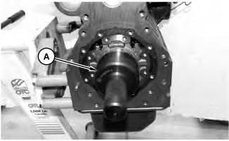
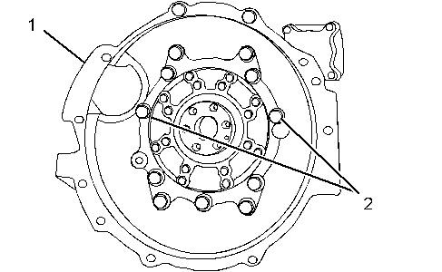
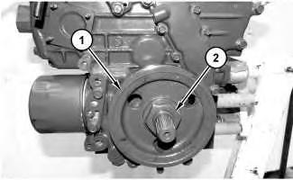
1. Remove bolts (2), bearing case cover (1), and the gaskets.
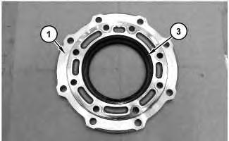
Illustration 2
2. Remove crankshaft rear seal (3) from bearing case cover (1).
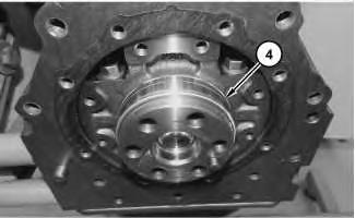
Illustration 3
3. Use a chisel to remove wear sleeve (4) from the crankshaft.
Illustration 1 g02715938 g02718254 g02718258Shutdown SIS
Previous Screen
Product: MINI HYD EXCAVATOR
Model: 305E2 CR MINI HYD EXCAVATOR DJX
Configuration: 305E2 CR Mini Hydraulic Excavator DJX00001-UP (MACHINE) POWERED BY C2.4 Engine
Disassembly and Assembly
C1.7, C1.8 and C2.4 Tier 4 Interim and EU Stage 3A Engines for Caterpillar Built Machines
Crankshaft Rear Seal - Install
SMCS - 1161-012
Installation Procedure
NOTICE
Keep all parts clean from contaminants.
Contaminants may cause rapid wear and shortened component life.
1. Position wear sleeve (4) on Tooling (A). Ensure that the crankshaft flange is clean, dry, and free from damage.
2. Apply Tooling (C) and use Tooling (A) to install the wear sleeve.
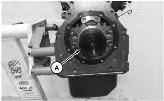 Illustration 1
g02718716
Illustration 2
g02718719
Illustration 3
g02715938
Illustration 1
g02718716
Illustration 2
g02718719
Illustration 3
g02715938
Illustration 4
g02718254
Note: Do not lubricate the crankshaft rear seal or the crankshaft flange. The crankshaft rear seal must be installed dry. Lubricate the inner rubber portion of the crankshaft rear seal.
3. Use Tooling (B) to install a new crankshaft rear seal (3) in bearing case cover (1).
4. Position the gaskets and bearing case cover (1) and install bolts (2). Position bearing case cover (1) with marking UP upward.
5. Apply engine oil to bolts (2).
6. Tighten bolts (2) to a torque of 24 to 27 N·m (18 to 20 lb ft). Tighten bolts (2) with an equal force on diagonal line.
End By:
a. Install the flywheel.
Shutdown SIS
Previous Screen
Product: MINI HYD EXCAVATOR
Model: 305E2 CR MINI HYD EXCAVATOR DJX
Configuration: 305E2 CR Mini Hydraulic Excavator DJX00001-UP (MACHINE) POWERED BY C2.4 Engine
Disassembly and Assembly
C1.7, C1.8 and C2.4 Tier 4 Interim and EU Stage 3A Engines for Caterpillar Built Machines
Flywheel Housing - Remove and Install
SMCS - 1157-010
Removal Procedure Table 1
Required Tools
Start By:
a. Remove the flywheel.
NOTICE
Keep all parts clean from contaminants.
Contaminants may cause rapid wear and shortened component life.
Illustration 1 g02731610
1. Remove two bolts (2) from flywheel housing (1).
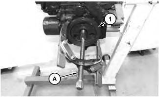
2. Install Tooling (A) into flywheel housing (1).
3. Install a suitable lifting device to flywheel housing (1). The weight of flywheel housing (1) is approximately 40 kg (88 lb).
4. Remove remaining 11 bolts (2) and from flywheel housing (1).
5. Remove flywheel housing (1) from the cylinder block.
6. Remove the gasket.
7. If necessary, remove the dowels from the cylinder block.
Installation Procedure
Table 2
Required Tools Tool
Keep all parts clean from contaminants.
Contaminants may cause rapid wear and shortened component life.
1. Ensure that the flywheel housing is clean and free from damage. If necessary, replace the flywheel housing.
Illustration 2 g02731610
2. Inspect the crankshaft rear seal for leaks. If there are any oil leaks, replace the crankshaft rear seal. Refer to Disassembly and Assembly, "Crankshaft Rear Seal - Remove" and refer to Disassembly and Assembly, "Crankshaft Rear Seal - Install" for the correct procedure.
3. Clean the rear face of the cylinder block. If necessary, install the dowels into the cylinder block.
4. Install Tooling (A) to the cylinder block.
5. Install the gasket.
6. Install a suitable lifting device to flywheel housing (1). The weight of flywheel housing (1) is approximately 40 kg (88 lb).
7. Use the lifting device to align flywheel housing (1) with Tooling (A). Install flywheel housing (1) to the cylinder block.
8. Install 11 bolts (2).
9. Remove Tooling (A). Install remaining two bolts (2).
10. Check the alignment of flywheel housing (1) with the crankshaft. Refer to System Operation, Testing and Adjusting, "Flywheel Housing - Inspect" for the correct procedure.
End By:
a. Install the flywheel.
Shutdown SIS
Previous Screen
Product: MINI HYD EXCAVATOR
Model: 305E2 CR MINI HYD EXCAVATOR DJX
Configuration: 305E2 CR Mini Hydraulic Excavator DJX00001-UP (MACHINE) POWERED BY C2.4 Engine
Disassembly and Assembly
C1.7, C1.8 and C2.4 Tier 4 Interim and EU Stage 3A Engines for Caterpillar Built Machines
Crankshaft Pulley - Remove and Install
SMCS - 1205-010
Removal Procedure
Table 1
Required Tools
Tool Part Number Part Description Qty
A 1P-2321 Puller As. 1
Start By:
a. Remove the alternator belt.
NOTICE
Keep all parts clean from contaminants.
Contaminants may cause rapid wear and shortened component life.
Illustration 1
g02718161
1. Use a suitable tool in order to prevent the crankshaft from rotating. Remove nut (2) in order to remove crankshaft pulley (1).
Illustration 2
g02718163
2. Position Tooling (A). Remove crankshaft pulley (1) from the crankshaft.
Installation Procedure
1. Install crankshaft pulley (1) in the reverse order of removal.
1. Tighten nut (2) to a torque of 138 - 156 N·m (102 - 115 lb ft).
Copyright 1993 - 2020 Caterpillar Inc.
All Rights Reserved.
Private Network For SIS Licensees.
Sun Feb 2 13:13:31 UTC+0800 2020
Shutdown SIS
Previous Screen
Product: MINI HYD EXCAVATOR
Model: 305E2 CR MINI HYD EXCAVATOR DJX
Configuration: 305E2 CR Mini Hydraulic Excavator DJX00001-UP (MACHINE) POWERED BY C2.4 Engine
Disassembly and Assembly
C1.7, C1.8 and C2.4 Tier 4 Interim and EU Stage 3A Engines for Caterpillar Built Machines
Crankshaft Front Seal - Remove
SMCS - 1160-011
Removal Procedure
Start By:
a. Remove the crankshaft pulley.
NOTICE
Keep all parts clean from contaminants.
Contaminants may cause rapid wear and shortened component life.
NOTICE
Care must be taken to ensure that fluids are contained during performance of inspection, maintenance, testing, adjusting and repair of the product. Be prepared to collect the fluid with suitable containers before opening any compartment or disassembling any component containing fluids.
Dispose of all fluids according to local regulations and mandates.
1. Remove key (1) and sleeve (2) from the crankshaft.
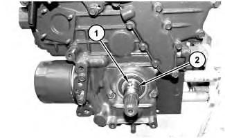
Illustration 2
2. Remove crankshaft front seal (3). Copyright 1993 - 2020 Caterpillar Inc. All Rights Reserved. Private Network For SIS Licensees.
g02717557
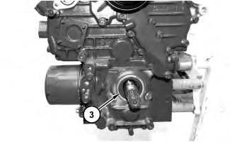 Illustration 1
g02717555
Illustration 1
g02717555
Shutdown SIS
Previous Screen
Product: MINI HYD EXCAVATOR
Model: 305E2 CR MINI HYD EXCAVATOR DJX
Configuration: 305E2 CR Mini Hydraulic Excavator DJX00001-UP (MACHINE) POWERED BY C2.4 Engine
Disassembly and Assembly
C1.7, C1.8 and C2.4 Tier 4 Interim and EU Stage 3A Engines for Caterpillar Built Machines
Crankshaft Front Seal - Install
SMCS - 1160-012
Installation Procedure
NOTICE
Keep all parts clean from contaminants.
Contaminants may cause rapid wear and shortened component life.
Note: The crankshaft front seal should be installed dry. Lubricate the inner rubber portion of the crankshaft front seal.
1. Inspect the nose of the crankshaft for damage. Ensure that the crankshaft is clean and dry.
g02717557
2. Position a new crankshaft front seal (3). Install crankshaft front seal (3).
3. Lubricate the inner rubber portion of the crankshaft front seal. Position sleeve (2) on the crankshaft and install key (1).
End By:
a. Install the crankshaft pulley.
Illustration 2 g02717555Shutdown SIS
Previous Screen
Product: MINI HYD EXCAVATOR
Model: 305E2 CR MINI HYD EXCAVATOR DJX
Configuration: 305E2 CR Mini Hydraulic Excavator DJX00001-UP (MACHINE) POWERED BY C2.4 Engine
Disassembly and Assembly
C1.7, C1.8 and C2.4 Tier 4 Interim and EU Stage 3A Engines for Caterpillar Built Machines
Idler Gear - Remove and Install
SMCS - 1206
Removal Procedure Table 1
Required Tools
Tool Part Number Part Description Qty
A 387-1314 Idler Gear Tool 1
Start By:
a. Remove the front housing.
NOTICE
Keep all parts clean from contaminants.
Contaminants may cause rapid wear and shortened component life.
NOTICE
Care must be taken to ensure that fluids are contained during performance of inspection, maintenance, testing, adjusting and repair of the product. Be prepared to collect the fluid with suitable containers before opening any compartment or disassembling any component containing fluids.
Dispose of all fluids according to local regulations and mandates.
Alignment of timing marks
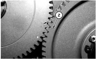
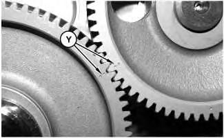
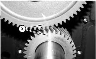 Illustration 1
g02720887
Illustration 2
g02720888
Illustration 3
g02720892
Illustration 1
g02720887
Illustration 2
g02720888
Illustration 3
g02720892
1. Ensure that Timing Marks (X) on the idler gear and the crankshaft gear are aligned. Refer to Illustration 1.
2. Ensure that Timing Marks (Y) on the idler gear and the camshaft gear are aligned. Refer to Illustration 2.
3. Ensure that Timing Marks (Z) on the idler gear and the fuel injection pump gear are aligned. Refer to Illustration 3.
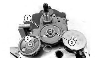
4. Remove retaining ring (2) and collar (3). Remove idler gear (1).
5. Remove idler gear (1) from the idler shaft.
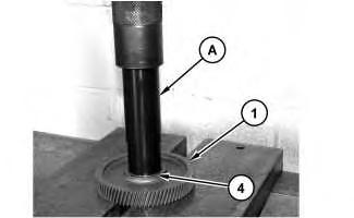
6. Use Tooling (A) to remove idler gear bearing (4) from idler gear (1).
Illustration 4 g02720894 Illustration 5 g02720895Suggest:
If the above button click is invalid.
Please download this document first, and then click the above link to download the complete manual.
Thank you so much for reading

7. If necessary, follow Steps 7.a and 7.b in order to remove idler shaft (5).
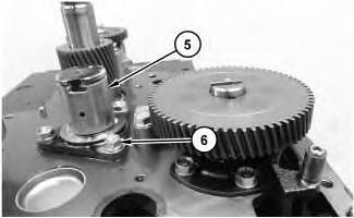
a. Make a temporary mark on the cylinder block in order to show the position of the oil hole.
b. Remove bolts (6) and the washers. Remove idler shaft (5) from the cylinder block.
Installation Procedure
1. Install idler gear (1) in the reverse order of removal.
a. Ensure that the gears, cylinder block surface, and idler gear (1) are clean and free from wear or damage. If necessary, replace any components that are worn or damaged.
b. Lubricate idler shaft (5) with clean engine oil.
c. Lubricate idler gear bearing surface (4) with clean engine oil.
d. Apply engine oil to bolts (6). Tighten bolts (6) to a torque of 24 to 27 N·m (18.0 to 20.0 lb ft).
Illustration 6 g02720896