Previous Screen
Product: MINI HYD EXCAVATOR
Model: 305.5E2 CR MINI HYD EXCAVATOR HRX
Configuration: 305.5E2CR Mini Hydraulic Excavator HRX00001-UP (MACHINE) POWERED BY C2.4 Engine
Disassembly and Assembly
C2.4 Tier 4 Final Engines for Caterpillar Built Machines
Camshaft - Remove and Install
SMCS - 1210-010
Removal Procedure
Start By:
a. Remove cylinder head.
NOTICE
Keep all parts clean from contaminants.
Contaminants may cause rapid wear and shortened component life.
Shutdown SIS
g06014635
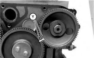
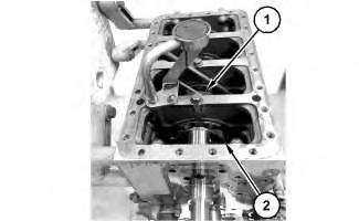
Illustration 2
2. Remove lifters (1).
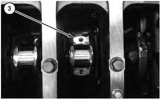
g06014606
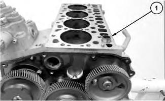
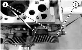
Illustration 3
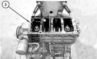
3. Remove bolts (2) and camshaft (3).
Installation Procedure
g06014643
1. Install camshaft (3) in the reverse order of removal.
a. Tighten bolts (2) to a torque of 24 N·m to 27 N·m (212 lb in to 239 lb in).
Copyright 1993 - 2020 Caterpillar Inc.
All Rights Reserved.
Private Network For SIS Licensees.
Sat Feb 8 18:35:32 UTC+0800 2020
Previous Screen
Product: MINI HYD EXCAVATOR
Model: 305.5E2 CR MINI HYD EXCAVATOR HRX
Configuration: 305.5E2CR Mini Hydraulic Excavator HRX00001-UP (MACHINE) POWERED BY C2.4 Engine
Disassembly and Assembly
C2.4 Tier 4 Final Engines for Caterpillar Built Machines
Camshaft Gear - Remove and Install
SMCS - 1210-010-GE
Removal Procedure
Table 1
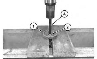
Required Tools Tool
A 1P-0510 Driver Group 1
B 8B-7551 Puller Assembly 1
Start By:
a. Remove the camshaft.
NOTICE
Keep all parts clean from contaminants.
Contaminants may cause rapid wear and shortened component life.
Shutdown SIS
NOTICE
Care must be taken to ensure that fluids are contained during performance of inspection, maintenance, testing, adjusting and repair of the product. Be prepared to collect the fluid with suitable containers
before opening any compartment or disassembling any component containing fluids.
Dispose of all fluids according to local regulations and mandates.
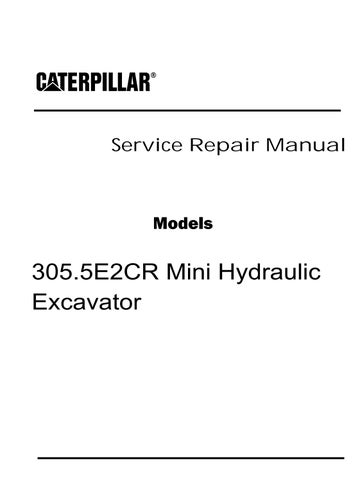
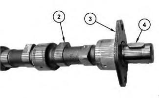
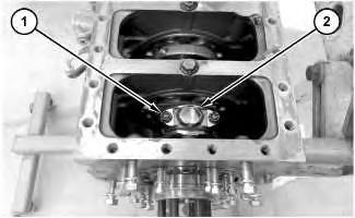
1. Use Tooling (A) to remove camshaft gear (1) from camshaft (2). Use Tooling (B) to install camshaft gear (1) onto camshaft (2).
2. Remove plate (3) from camshaft (2).
3. If necessary, remove the key from the nose of the camshaft.
Installation Procedure
1. Install camshaft gear (1) in the reverse order of removal.
a. Ensure that the camshaft gear and the key are clean and free from wear and damage.
Sat Feb 8 18:36:29 UTC+0800 2020
Illustration 1 g02721209 Illustration 2 g02721212Shutdown SIS
Previous Screen
Product: MINI HYD EXCAVATOR
Model: 305.5E2 CR MINI HYD EXCAVATOR HRX
Configuration: 305.5E2CR Mini Hydraulic Excavator HRX00001-UP (MACHINE) POWERED BY C2.4 Engine
Disassembly and Assembly
C2.4 Tier 4 Final Engines for Caterpillar Built Machines
Engine Oil Pan - Remove and Install
SMCS - 1302-010
Removal Procedure
Table 1
Required Tooling Tool
NOTICE
Care must be taken to ensure that fluids are contained during performance of inspection, maintenance, testing, adjusting, and repair of the product. Be prepared to collect the fluid with suitable containers before opening any compartment or disassembling any component containing fluids.
Refer to Special Publication, NENG2500, "Dealer Service Tool Catalog" for tools and supplies suitable to collect and contain fluids on Cat® products.
Dispose of all fluids according to local regulations and mandates.
1. Drain the engine oil and filter. Refer to Operation and Maintenance Manual, "Engine Oil and Filter - Change" for the proper draining and filling procedures.
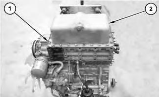
2. Remove bolts (1) and engine oil pan (2).
3. Remove gasket (3) from the cylinder block and the oil pan.
Installation Procedure
1. Install engine oil pan (2) in the reverse order of removal.
a. Apply Tooling (A) to the cylinder block surface.
Previous Screen
Product: MINI HYD EXCAVATOR
Model: 305.5E2 CR MINI HYD EXCAVATOR HRX
Configuration: 305.5E2CR Mini Hydraulic Excavator HRX00001-UP (MACHINE) POWERED BY C2.4 Engine
Disassembly and Assembly
C2.4 Tier 4 Final Engines for Caterpillar Built Machines Media
Piston and Connecting Rods - Remove and Install
SMCS - 1225-010
Removal Procedure
Table 1 Required Tooling
Tool
A 456-7967 Piston ring compressor 1
Start By:
a. Remove cylinder head.
b. Remove oil pan.
NOTICE
Keep all parts clean from contaminants.
Contaminants may cause rapid wear and shortened component life.
Shutdown SIS
NOTICE
Discard all used Connecting Rod fasteners.
Illustration 1 g06015326
1. Remove bolts (1) and connecting rod cap (2).
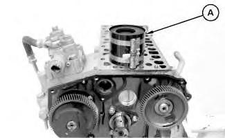
Illustration 2 g06015587
2. Carefully push connecting rod (3) and the piston into the cylinder bore until they are clear of the crankshaft and out of the cylinder block.
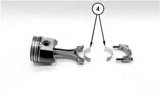
Note: The connecting rod and the connecting rod cap should have an etched Number (X) on the side. The number on the connecting rod and the connecting rod cap must match. Make a temporary mark on the connecting rod and the connecting rod cap to identify the cylinder number.
g06015618
3. Remove connecting rod bearings (4).
4. Repeat Step 1 through Step 3 for remaining pistons and connecting rods.
Installation Procedure
1. Install the connecting rods and the pistons in the reverse order of removal.
Note: Ensure that the piston and the connecting rod assembly are installed in the correct cylinder.
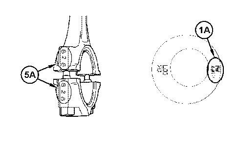
g02840445
a. The mark (5A) on the connecting rod must align with the fuel pump. Mark (1A) on the piston must align with the flywheel.
b. Lubricate connecting rod bearings with clean engine oil.
Note: Install the bearing shells for the connecting rods dry when clearance checks are performed. Refer to Disassembly and Assembly, "Bearing Clearance - Check" for the correct procedure. Apply clean engine oil to the bearing shells for the connecting rods during final assembly.
c. Install connecting rod bearings (4) with locating tabs correctly seated into slots.
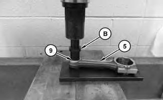
d. Use Tooling (A) to install the piston and connecting rod assembly.
Note: Apply clean engine oil to the cylinder bore, to the piston rings and to the outer surface of the piston
e. Install new bolts (1) to the connecting rod (3). Apply clean engine oil to the threads of bolts (1) and tighten to a torque of 40 N·m to 45 N·m (30 lb ft to 33 lb ft).
Note: Ensure that the installed connecting rod assembly has side play. Rotate the crankshaft to ensure that there is no binding.
Shutdown SIS
Previous Screen
Product: MINI HYD EXCAVATOR
Model: 305.5E2 CR MINI HYD EXCAVATOR HRX
Configuration: 305.5E2CR Mini Hydraulic Excavator HRX00001-UP (MACHINE) POWERED BY C2.4 Engine
Disassembly and Assembly
C2.4 Tier 4 Final Engines for Caterpillar Built Machines Media
Pistons and Connecting Rods - Disassemble
SMCS - 1225-015
Disassembly Procedure
Table 1
Required Tools Tool
A 1U-6683 Ring Expander 1
B 387-1313 Piston Wrist Pin Tool 1
Start By:
a. Remove the pistons and the connecting rods.
Note: Make a temporary mark on the components of the piston and connecting rod assembly. Marking the components will ensure that the components of each piston and connecting rod assembly can be reinstalled in the original cylinder. Mark the underside of the piston on the front pin boss. Do not interchange components.
NOTICE
Keep all parts clean from contaminants.
Contaminants may cause rapid wear and shortened component life.
1. Position the piston and connecting rod in a soft jaw vise. Use Tooling (A) to remove three rings (2) from piston (1).
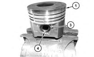
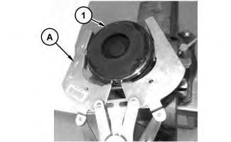
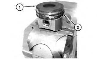 Illustration 1
g02723365
Illustration 2
g02723368
Illustration 3
g02723373
Illustration 1
g02723365
Illustration 2
g02723368
Illustration 3
g02723373
g02723375
2. Remove retaining ring (4) and remove piston wrist pin (3) from piston (1).
Note: Note the position of the forged mark on the piston and the marks on the rod. The forged marks are for the purposes of correct orientation of the connecting rod assembly and piston assembly.
3. If necessary, remove bolts (7) and connecting rod bearings (6) from connecting rod (5) and connecting rod cap (8). Inspect connecting rod bushing (9).
4. Place the piston on a suitable surface with the crown upward. Use Tooling (B) to remove connecting rod bushing (9) from connecting rod (5).
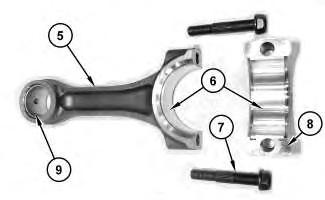
5. Inspect the connecting rod for wear and damage. If necessary, replace connecting rod (5) or replace the connecting rod bushing (9).
Note: If the connecting rod or the bush for the piston pin are replaced, refer to Specifications, "Connecting Rods" for the correct procedure.
6. Repeat Step 1 through Step 5 to disassemble the remaining pistons and connecting rods.
Illustration 4 Illustration 5 g02836798Previous Screen
Product: MINI HYD EXCAVATOR
Model: 305.5E2 CR MINI HYD EXCAVATOR HRX
Configuration: 305.5E2CR Mini Hydraulic Excavator HRX00001-UP (MACHINE) POWERED BY C2.4 Engine
Disassembly and Assembly
C2.4 Tier 4 Final Engines for Caterpillar Built Machines
Pistons and Connecting Rods - Assemble
SMCS - 1225-016
Assembly Procedure
Table 1
Required Tools
A 1U-6683 Ring Expander 1
B 387-1313 Piston Wrist Pin Tool 1
NOTICE
Keep all parts clean from contaminants.
Contaminants may cause rapid wear and shortened component life.
Shutdown SIS
1. Ensure that all components are clean and free from wear and damage. If necessary, replace any components that are worn or damaged.
2. Inspect the connecting rod for wear and damage. If necessary, replace connecting rod (5) or replace connecting rod bushing (9).
Note: If connecting rod (5) or the bushing (9) for connecting rod pin are replaced, refer to Specifications, "Connecting Rods" for the correct procedure.
3. Place the piston on a suitable surface with the crown upward. Use Tooling (B) to install connecting rod bushing (9) into connecting rod (5).
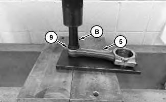 Illustration 1
g02836831
Illustration 2
g02723373
Illustration 3
g02723375
Illustration 1
g02836831
Illustration 2
g02723373
Illustration 3
g02723375
4. Check connecting rod bushing (9). If necessary, install connecting rod bearings (6) into connecting rod (5) and connecting rod cap (8). Inspect bolts (7) or replace with new for assembly later.
5. Lubricate the bore for the piston wrist pin (3) with clean engine oil.
6. Place piston (1) on a suitable surface with the crown downward. Position connecting rod (5) with the forged markings on the piston and connecting rod in the correct orientation.
Note: The mark (5A) on the connecting rod (5) must align with the fuel pump. Mark (1A) on the piston (1) must align with the flywheel.
7. Install piston wrist pin (3) into piston (1). Install retaining ring (4).
Illustration 4 g02840445
Illustration 5 g02723365
Illustration 6
g02723368
8. Position the connecting rod and piston (1) into a soft jaw vise. Use Tooling (A) to install three rings (2) onto piston (1).
Illustration 7
g06045622
9. If the original piston is assembled, follow Step 9.a through Step 9.e to install the piston rings.
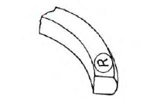
a. Position the spring for the oil control ring into the oil ring groove in piston (1). The central wire must be located inside the end of the spring.
b. Position the oil control ring with the manufacturing mark in the upward position as shown in Illustration 7. Use Tooling (A) to install over the piston and the spring.
Note: Ensure that the central wire is 180 degrees from the ring gap.
c. Use Tooling (A) to install the intermediate compression ring into the second groove in piston (1). The manufacturing mark must be upward. The chamfer on the inner face must be downward.
d. Use Tooling (A) to install top the compression ring into the top groove in piston (1). The manufacturing mark must be upward.
e. Position piston ring (2) gaps at 120 degrees away from each other.
10. Repeat Step 2 through Step 9.e for the remaining piston and connecting rod assemblies.
Shutdown SIS
Previous Screen
Product: MINI HYD EXCAVATOR
Model: 305.5E2 CR MINI HYD EXCAVATOR HRX
Configuration: 305.5E2CR Mini Hydraulic Excavator HRX00001-UP (MACHINE) POWERED BY C2.4 Engine
Disassembly and Assembly
C2.4 Tier 4 Final Engines for Caterpillar Built Machines
Crankshaft - Remove
SMCS - 1202-011
Removal Procedure
Start By:
a. Remove pistons and connecting rods.
NOTICE
If the crankshaft has been reground or replaced, the height of the piston above the cylinder block must be inspected. It is necessary to remove the cylinder head to inspect the height of the piston above the cylinder block.
Note: Before you disassemble, measure the side clearance of the crankshaft. Measure it when you reassemble.
Suggest:
If the above button click is invalid.
Please download this document first, and then click the above link to download the complete manual.
Thank you so much for reading

Illustration 1 g06016404
1. Remove bolts (1).
Illustration 2 g06016439
2. Rotate crankshaft (2) and align the crankshaft journals with the reliefs (X) in the Cylinder Block. Use two people to pull the crankshaft out of the cylinder block. The weight of crankshaft (2) is approximately 24 kg (53 lb).
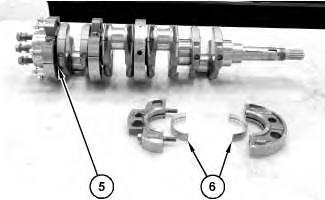
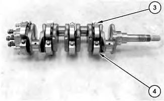
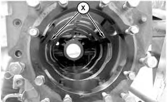
Illustration 3 g06016479
3. Remove bolts (3) and main bearing case assemblies (4).