Shutdown SIS
Previous Screen
Product: MINI HYD EXCAVATOR
Model: 305.5E2 CR MINI HYD EXCAVATOR FR5
Configuration: 305.5E2 CR Mini Hydraulic Excavator FR500001-UP (MACHINE) POWERED BY C2.4 Engine
Disassembly and Assembly
C2.4 Tier 4 Final Engines for Caterpillar Built Machines
Fuel Manifold (Rail) - Remove and Install
SMCS - 1702-010
Removal Procedure
Contact with high pressure fuel may cause fluid penetration and burn hazards. High pressure fuel spray may cause a fire hazard. Failure to follow these inspection, maintenance and service instructions may cause personal injury or death.
NOTICE
Care must be taken to ensure that fluids are contained during performance of inspection, maintenance, testing, adjusting and repair of the product. Be prepared to collect the fluid with suitable containers before opening any compartment or disassembling any component containing fluids.
Dispose of all fluids according to local regulations and mandates.
Start By:
a. Remove fuel injection lines.
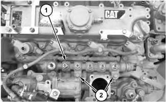
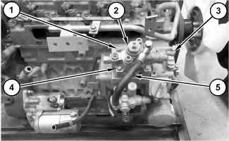
Illustration 1
1. Remove bolts (2) and fuel manifold (1).
g06008153
Note: Do not remove the pressure limiter and the rail pressure sensor from fuel manifold (1).
Note: When removing fuel manifold (1) do not hold it by the pressure limiter and the rail pressure sensor.
Installation Procedure
1. Install fuel manifold (1) in the reverse order of removal.
a. Tighten bolts (2) to a torque of 24 N·m to 27 N·m (212 lb in to 239 lb in). Copyright 1993 - 2020 Caterpillar Inc.
Shutdown SIS
Previous Screen
Product: MINI HYD EXCAVATOR
Model: 305.5E2 CR MINI HYD EXCAVATOR FR5
Configuration: 305.5E2 CR Mini Hydraulic Excavator FR500001-UP (MACHINE) POWERED BY C2.4 Engine
Disassembly and Assembly
C2.4 Tier 4 Final Engines for Caterpillar Built Machines
Fuel Injection Lines - Remove and Install
SMCS - 1252-010
Removal Procedure
Contact with high pressure fuel may cause fluid penetration and burn hazards. High pressure fuel spray may cause a fire hazard. Failure to follow these inspection, maintenance and service instructions may cause personal injury or death.
NOTICE
Care must be taken to ensure that fluids are contained during performance of inspection, maintenance, testing, adjusting and repair of the product. Be prepared to collect the fluid with suitable containers before opening any compartment or disassembling any component containing fluids.
Dispose of all fluids according to local regulations and mandates.
1. Turn the fuel supply to the OFF position.
2. Turn the battery disconnect switch to the OFF position.
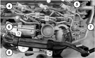
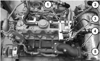
3. Remove bolt (3) and clamp (1). Disconnect hose assembly (2).
4. Remove bolt (8) and clamps (5). Disconnect hose assembly (7).
5. Remove bolts (4) and intake throttle valve (6).
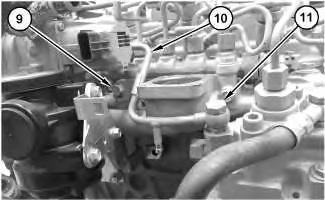
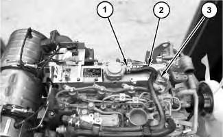
6. Remove bolt (9), bolt (11), and tube assembly (10).
Note: Cap and plug all fuel lines to prevent contaminating fuel system.
Illustration 1 g06007993 Illustration 2 g06008011 Illustration 3 g06008040Illustration 4
g06008098
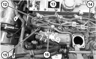
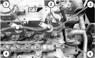
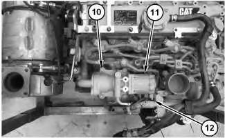
7. Remove clamp (16). Disconnect hose assembly (15).
8. Remove bolt (12), bolt (14), and tube assembly (13).
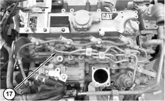
Illustration 5
9. Remove fuel injection lines (17).
g06008091
Note: Cap and plug all fuel lines to prevent contaminating fuel system.
Installation Procedure
1. Install fuel injection lines (17) in the reverse order of removal.
a. Tighten the retaining nuts of fuel injection lines (17) to a torque of 25 N·m to 29 N·m (221 lb in to 257 lb in). Copyright 1993 - 2020 Caterpillar Inc.
Shutdown SIS
Previous Screen
Product: MINI HYD EXCAVATOR
Model: 305.5E2 CR MINI HYD EXCAVATOR FR5
Configuration: 305.5E2 CR Mini Hydraulic Excavator FR500001-UP (MACHINE) POWERED BY C2.4 Engine
Disassembly and Assembly
C2.4 Tier 4 Final Engines for Caterpillar Built Machines
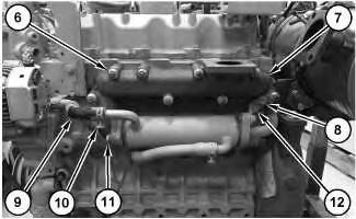
Exhaust Gas Recirculation Cooler - Remove and Install
SMCS - 1087; 108C-010
Removal Procedure
Sulfuric Acid Burn Hazard may cause serious personal injury or death.
The exhaust gas cooler may contain a small amount of sulfuric acid. The use of fuel with sulfur levels greater than 15 ppm may increase the amount of sulfuric acid formed. The sulfuric acid may spill from the cooler during service of the engine. The sulfuric acid will burn the eyes, skin and clothing on contact. Always wear the appropriate personal protective equipment (PPE) that is noted on a material safety data sheet (MSDS) for sulfuric acid. Always follow the directions for first aid that are noted on a material safety data sheet (MSDS) for sulfuric acid.
Note: Plug or cap all open ports with new plugs or caps.
1. Drain the coolant. Refer to Operation and Maintenance Manual, "Cooling System CoolantChange" for the correct draining and filling procedures.
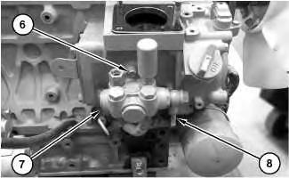
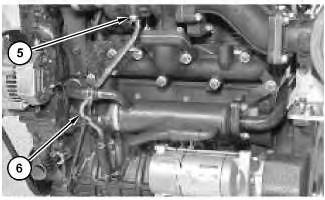
2. Remove clamp (2) and hose assembly (1).
3. Remove clamp (8) and hose assembly (7).
4. Remove bolt (5) and bracket (4).
5. Remove bolts (6), bolts (9), and exhaust gas recirculation cooler (3).
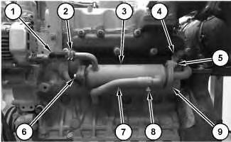
Installation Procedure
1. Install exhaust gas recirculation cooler (3) in the reverse order of removal.
Previous Screen
Product: MINI HYD EXCAVATOR
Model: 305.5E2 CR MINI HYD EXCAVATOR FR5
Configuration: 305.5E2 CR Mini Hydraulic Excavator FR500001-UP (MACHINE) POWERED BY C2.4 Engine
Disassembly and Assembly
C2.4 Tier 4 Final Engines for Caterpillar Built Machines
Fuel Injection Pump - Remove and Install
SMCS - 1251-010
Removal Procedure
Start By:
a. Remove inlet manifold.
Illustration 1
1. Disconnect harness assembly (3) (not shown).
2. Disconnect hose assembly (5).
3. Remove nuts (1), bolts (4), and fuel injection pump (2).
Shutdown SIS
4. Disconnect hose assembly (8) (not shown).
5. Remove bolts (6) and fuel pump (7).
Installation Procedure
1. Install fuel injection pump (7) in the reverse order of removal.
a. Tighten nuts (1) to a torque of 24 N·m to 27 N·m (212 lb in to 239 lb in).
Shutdown SIS
Previous Screen
Product: MINI HYD EXCAVATOR
Model: 305.5E2 CR MINI HYD EXCAVATOR FR5
Configuration: 305.5E2 CR Mini Hydraulic Excavator FR500001-UP (MACHINE) POWERED BY C2.4 Engine
Disassembly and Assembly
C2.4 Tier 4 Final Engines for Caterpillar Built Machines
Electronic Unit Injector - Remove and Install
SMCS - 1290-010
Removal Procedure
Contact with high pressure fuel may cause fluid penetration and burn hazards. High pressure fuel spray may cause a fire hazard. Failure to follow these inspection, maintenance and service instructions may cause personal injury or death.
NOTICE
Ensure that all adjustments and repairs that are carried out to the fuel system are performed by authorised personnel that have the correct training.
Before begining ANY work on the fuel system, refer to Operation and Maintenance Manual, "General Hazard Information and High Pressure Fuel Lines" for safety information.
Refer to Systems Operation, Testing and Adjusting Manual, "Cleanliness of Fuel System Components" for detailed information on the standards of cleanliness that must be observed during ALL work on the fuel system.
Care must be taken to ensure that fluids are contained during performance of inspection, maintenance, testing, adjusting and repair of the product. Be prepared to collect the fluid with suitable containers before opening any compartment or disassembling any component containing fluids.
Dispose of all fluids according to local regulations and mandates.
Start By:
a. Remove fuel injection lines.
Illustration 1
g06008227
1. Remove clip (2). Disconnect hose assembly (1).
2. Remove bolt (5), clamp (4), and electronic unit injector (3).
Installation Procedure
1. Install electronic unit injector (3) in the reverse order of removal.
a. Tighten bolt (5) to a torque of 24 N·m to 27 N·m (212 lb in to 248 lb in).
Note: If new injectors are installed, refer to REHS9707 to install new injector trim codes in the Engine ECM and to register them on-line
Copyright 1993 - 2020 Caterpillar Inc. All Rights Reserved. Private Network For SIS Licensees.
Shutdown SIS
Previous Screen
Product: MINI HYD EXCAVATOR
Model: 305.5E2 CR MINI HYD EXCAVATOR FR5
Configuration: 305.5E2 CR Mini Hydraulic Excavator FR500001-UP (MACHINE) POWERED BY C2.4 Engine
Disassembly and Assembly
C2.4 Tier 4 Final Engines for Caterpillar Built Machines
Turbocharger - Remove and Install
SMCS - 1052-010
Removal Procedure
Drain the cooling system into a suitable container for storage or disposal. Refer to Operation and Maintenance Manual, "Cooling System Coolant (ELC) - Change".
NOTICE
Keep all parts clean from contaminants. Contaminants may cause rapid wear and shortened component life.
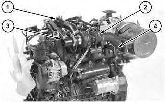
g06044516
1.
2. Remove muffler flange (4).
3. Disconnect intake hose (3).
4. Remove screw (5).
5. Remove return pipe (crankcase side) (6).
6. Remove turbocharger (2).
Installation Procedure
1. Install turbocharger (2) in the reverse order of removal.
Illustration 2 g06044524Shutdown SIS
Previous Screen
Product: MINI HYD EXCAVATOR
Model: 305.5E2 CR MINI HYD EXCAVATOR FR5
Configuration: 305.5E2 CR Mini Hydraulic Excavator FR500001-UP (MACHINE) POWERED BY C2.4 Engine
Disassembly and Assembly
C2.4 Tier 4 Final Engines for Caterpillar Built Machines
Exhaust Gas Recirculation Valve - Remove and Install
SMCS - 108N-010
Removal Procedure
Personal injury can result from hot coolant, steam and alkali.
At operating temperature, engine coolant is hot and under pressure. The radiator and all lines to heaters or the engine contain hot coolant or steam. Any contact can cause severe burns.
Remove cooling system pressure cap slowly to relieve pressure only when engine is stopped and cooling system pressure cap is cool enough to touch with your bare hand.
Do not attempt to tighten hose connections when the coolant is hot, the hose can come off causing burns.
Cooling System Coolant Additive contains alkali. Avoid contact with skin and eyes.
NOTICE
Care must be taken to ensure that fluids are contained during performance of inspection, maintenance, testing, adjusting, and repair of the product. Be prepared to collect the fluid with suitable containers before opening any compartment or disassembling any component containing fluids.
Refer to Special Publication, NENG2500, "Dealer Service Tool Catalog" for tools and supplies suitable to collect and contain fluids on Cat® products.
Dispose of all fluids according to local regulations and mandates.
Note: Refer to Specifications, "Engine Design" for non-specified engine torque values.
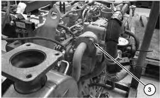
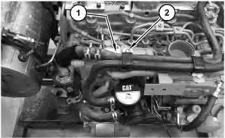 Illustration 1
g06002555
1. Remove bolt (1) and bolt (2).
Illustration 2
g06002560
2. Remove bolts (3).
Illustration 1
g06002555
1. Remove bolt (1) and bolt (2).
Illustration 2
g06002560
2. Remove bolts (3).
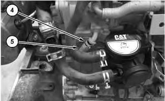
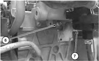
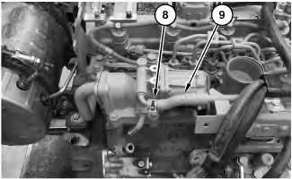 Illustration 3
g06002566
3. Remove clamp (4). Disconnect hose assembly (5).
Illustration 4
g06002585
4. Remove bolt (6). Position breather assembly (7) out of the way.
Illustration 5
g06002718
5. Remove clamp (8) . Disconnect hose assembly (9).
Illustration 3
g06002566
3. Remove clamp (4). Disconnect hose assembly (5).
Illustration 4
g06002585
4. Remove bolt (6). Position breather assembly (7) out of the way.
Illustration 5
g06002718
5. Remove clamp (8) . Disconnect hose assembly (9).
6. Disconnect harness assembly (12) (not shown).
7. Remove bolts (10) and exhaust gas recirculation valve (11).
Installation Procedure
1. Install exhaust gas recirculation valve (11) in the reverse order of removal.
Previous Screen
Product: MINI HYD EXCAVATOR
Model: 305.5E2 CR MINI HYD EXCAVATOR FR5
Configuration: 305.5E2 CR Mini Hydraulic Excavator FR500001-UP (MACHINE) POWERED BY C2.4 Engine
Disassembly and Assembly
C2.4 Tier 4 Final Engines for Caterpillar Built Machines
Exhaust Manifold - Remove and Install
SMCS - 1059-010
Removal Procedure
Illustration 1
1.
Shutdown SIS
3. Remove clamp (10) and hose (9).
4. Remove bolt (8) and bracket (12).
5. Remove bolts (11), nuts (6), and exhaust manifold (7).
Installation Procedure
1. Install exhaust manifold (7) in the reverse order of removal.
a. Tighten bolts (3) to a torque of 24 N·m to 27 N·m (212 lb in to 239 lb in).
Previous Screen
Product: MINI HYD EXCAVATOR
Model: 305.5E2 CR MINI HYD EXCAVATOR FR5
Configuration: 305.5E2 CR Mini Hydraulic Excavator FR500001-UP (MACHINE) POWERED BY C2.4 Engine
Disassembly and Assembly
C2.4 Tier 4 Final Engines for Caterpillar Built Machines
Diesel Particulate Filter - Disassemble
SMCS - 108F-015
Disassemble Procedure
Wear goggles, gloves, protective clothing, and a National Institute for Occupational Safety and Health (NIOSH) approved P95 or N95 halfface respirator when handling a used Diesel Particulate Filter or Catalytic Converter Muffler. Failure to do so could result in personal injury.
Shutdown SIS
The muffler, catalytic converter/muffler, and diesel particulate filter will become extremely hot during engine operation. A hot muffler, catalytic converter/muffler and diesel particulate filter can cause serious burns. Allow adequate cooling time before working on or near the muffler, catalytic converter/muffler and diesel particulate filter.
NOTICE
Do not strike any part of the assembly of the Diesel Particulate Filter (DPF). Do not allow any object to contact the internal element of the
Suggest:
If the above button click is invalid.
Please download this document first, and then click the above link to download the complete manual.
Thank you so much for reading

DPF. If the internal element of the DPF becomes damaged, the assembly must be replaced.
NOTICE
Before starting of disassembling the diesel particulate filter, put the alignment marks on each of the parts, the diesel particulate filter, the diesel oxidation catalyst, and the muffler.
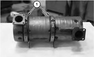
1. Remove band clamps (1).
2. Separate muffler (2), diesel particulate filter (3), and diesel oxidation catalyst (4).
Copyright 1993 - 2020 Caterpillar Inc. All Rights Reserved.
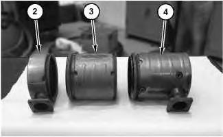 Illustration 1 g06001247
Illustration 2 g06001291
Illustration 1 g06001247
Illustration 2 g06001291