Shutdown SIS
Previous Screen
Product: MINI HYD EXCAVATOR
Model: 305.5E2 CR MINI HYD EXCAVATOR NC5
Configuration: 305.5E2 CR Mini Hydraulic Excavator NC500001-UP (MACHINE) POWERED BY C2.4 Engine
Disassembly and Assembly
C2.4 Tier 4 Final Engines for Caterpillar Built Machines
Inlet Manifold - Remove and Install
SMCS - 1058-010
Removal Procedure
Start By:
a. Remove exhaust gas recirculation valve.
b. Remove fuel injection lines.
c. Remove fuel manifold (rail).
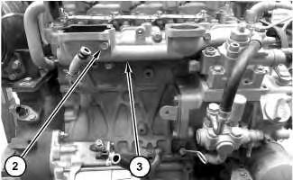
1. Remove bolt

2. Remove bolts (2) and inlet manifold (3).
Installation Procedure
1. Install inlet manifold (3) in the reverse order of removal.
Shutdown SIS
Previous Screen
Product: MINI HYD EXCAVATOR
Model: 305.5E2 CR MINI HYD EXCAVATOR NC5
Configuration: 305.5E2 CR Mini Hydraulic Excavator NC500001-UP (MACHINE) POWERED BY C2.4 Engine
Disassembly and Assembly
C2.4 Tier 4 Final Engines for Caterpillar Built Machines
Inlet and Exhaust Valves - Remove and Install
SMCS - 1105-010
Removal Procedure
Table 1 Required Tooling
Tool Part Number Part Description Qty
A 5S-1330 Valve Spring Compressor 1
Start By:
a. Remove cylinder head.
NOTICE
Keep all parts clean from contaminants.
Contaminants may cause rapid wear and shortened component life.
1. Clean the bottom mating surface of the cylinder head. Check the depth of the valves below the face of the cylinder head before the valve springs are removed. Refer to Specifications, "Cylinder Head Valves" for the correct dimensions.
2. Place a temporary identification mark on the heads of the valves to identify the correct position.
3. Use a suitable lifting device to position the cylinder head with the valve springs upward. The weight of the cylinder head is approximately 28 kg (61 lb).
Personal injury can result from being struck by parts propelled by a released spring force.
Make sure to wear all necessary protective equipment. Follow the recommended procedure and use all recommended tooling to release the spring force.
4. Install Tooling (A) in position on the cylinder head and compress the valve spring to remove inlet and exhaust valves (1).

NOTICE
Ensure that the valve spring is compressed squarely or damage to the valve stem may occur.
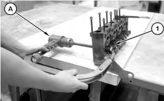 Illustration 1
g06013564
Illustration 2
g06013581
Illustration 1
g06013564
Illustration 2
g06013581
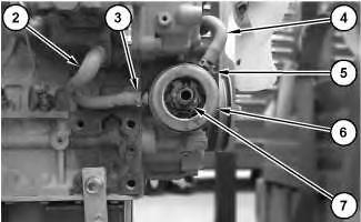
5. Remove valve cap (2). Apply sufficient pressure to Tooling (A) to remove valve keepers (3).
6. Slowly release pressure on Tooling (A).
7. Place a temporary identification make on valve spring (5) to identify the correct position.
8. Remove valve spring retainer (4), valve spring (5), and valve (6).
9. Remove Tooling (A).
10. Remove valve stem seals (7) from the cylinder head.
11. Repeat Step 4 through Step 10 for the remaining valves.
Installation Procedure
1. Install valves (6) in the reverse order of removal.
2. Clean all components of the cylinder head assembly. Ensure that all posts, all coolant passages, and all lubrication passages in the cylinder head are free from debris. Follow Step 2.a through Step 2.e to inspect components of the cylinder head assembly. Replace any components that are worn or damaged.
a. Inspect the cylinder head for wear and for damage. Refer to System Operation, Testing and Adjusting, "Cylinder Head Inspect" for the correct procedure.

b. Inspect the valve seats for wear and for damage. Refer to Specifications, "Cylinder Head Valves" for further information.
c. Inspect the valve guides for wear and for damage. Refer to Specifications, "Cylinder Head Valves" for further information.
d. Inspect the valves (6) for wear and for damage. Refer to Specifications, "Cylinder Head Valves" for further information.
Illustration 3 g06013653e. Inspect valve springs (5) for damage and for the correct length. Refer to Specifications, "Cylinder Head Valves" for further information.
3. Lubricate the stems of valves (6) with clean engine oil. Install valves (6) in the appropriate positions in the cylinder head. Check the depth of the valves below the face of the cylinder head. Refer to Specifications, "Cylinder Head Valves" for more information.
Shutdown SIS
Previous Screen
Product: MINI HYD EXCAVATOR
Model: 305.5E2 CR MINI HYD EXCAVATOR NC5
Configuration: 305.5E2 CR Mini Hydraulic Excavator NC500001-UP (MACHINE) POWERED BY C2.4 Engine
Disassembly and Assembly
C2.4 Tier 4 Final Engines for Caterpillar Built Machines
Engine Oil Cooler - Remove and Install
SMCS - 1378-010
Removal Procedure
NOTICE
Keep all parts clean from contaminants.
Contaminants may cause rapid wear and shortened component life.
NOTICE
Care must be taken to ensure that fluids are contained during performance of inspection, maintenance, testing, adjusting and repair of the product. Be prepared to collect the fluid with suitable containers before opening any compartment or disassembling any component containing fluids.
Dispose of all fluids according to local regulations and mandates.
1. Drain the coolant. Refer to Operation and Maintenance Manual, "Cooling System CoolantChange" for the correct draining and filling procedures.
Illustration 1 g06003514
2. Remove engine oil filter (1).
Illustration 2 g06003538
3. Remove clamp (3) and clamp (5). Disconnect hose assembly (2) and hose assembly (4).

4. Remove connector (7), engine oil cooler (6), and the collar.
Installation Procedure
1. Install engine oil cooler (6) in the reverse order of removal.
a. Tighten connector (7) to a torque of 40 N·m to 44 N·m (30 lb ft to 32 lb ft).
Copyright 1993 - 2020 Caterpillar Inc. All Rights Reserved. Private Network For SIS Licensees.
Fri Feb 7 23:14:19 UTC+0800 2020
Shutdown SIS
Previous Screen
Product: MINI HYD EXCAVATOR
Model: 305.5E2 CR MINI HYD EXCAVATOR NC5
Configuration: 305.5E2 CR Mini Hydraulic Excavator NC500001-UP (MACHINE) POWERED BY C2.4 Engine
Disassembly and Assembly
C2.4 Tier 4 Final Engines for Caterpillar Built Machines Media
Engine Oil Pump - Remove and Install
SMCS - 1304-010; 1315-010
Removal Procedure Table 1
Required Tooling Tool
A 1P-2321 Puller As. 1
Start By:
a. Remove front housing. Keep all parts clean from contaminants. Contaminants may cause rapid wear and shortened component life.
NOTICE
Care must be taken to ensure that fluids are contained during performance of inspection, maintenance, testing, adjusting and repair of the product. Be prepared to collect the fluid with suitable containers before opening any compartment or disassembling any component containing fluids.
Dispose of all fluids according to local regulations and mandates.
1. Remove nut (3).
2. Use Tooling (A) to remove gear (1).
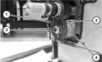
3. Remove bolts (2), engine oil pump (4), and the gasket.
Installation Procedure
1. Install engine oil pump (4) in the reverse order of removal.
Shutdown SIS
Previous Screen
Product: MINI HYD EXCAVATOR
Model: 305.5E2 CR MINI HYD EXCAVATOR NC5
Configuration: 305.5E2 CR Mini Hydraulic Excavator NC500001-UP (MACHINE) POWERED BY C2.4 Engine
Disassembly and Assembly
C2.4 Tier 4 Final Engines for Caterpillar Built Machines
Water Pump - Remove and Install
SMCS - 1361-011; 1361-012
Removal Procedure
NOTICE
Keep all parts clean from contaminants.
Contaminants may cause rapid wear and shortened component life.
NOTICE
Care must be taken to ensure that fluids are contained during performance of inspection, maintenance, testing, adjusting and repair of the product. Be prepared to collect the fluid with suitable containers before opening any compartment or disassembling any component containing fluids.
Dispose of all fluids according to local regulations and mandates.
1. Drain the coolant. Refer to Operation and Maintenance Manual, "Cooling System CoolantChange" for the correct draining and filling procedures.

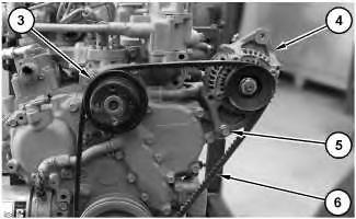
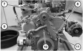 Illustration 1
g06003853
2. Remove bolts (2), suction fan (1), and the fan spacer.
Illustration 2
g06003869
3. Loosen bolt (5), the bolts, and the bracket assembly (not shown). Move alternator (4) and remove belt (6) .
4. Remove pulley (3).
Illustration 3 g06003956
5. Remove clamp (10) and hose assembly (9).
Illustration 1
g06003853
2. Remove bolts (2), suction fan (1), and the fan spacer.
Illustration 2
g06003869
3. Loosen bolt (5), the bolts, and the bracket assembly (not shown). Move alternator (4) and remove belt (6) .
4. Remove pulley (3).
Illustration 3 g06003956
5. Remove clamp (10) and hose assembly (9).
6. Remove nut (7), bolts (8), water pump (11), and the gasket.


 Illustration 1
Illustration 2
Illustration 1
Illustration 2
